

Page 1
DFE-908x
DFE-908
Ethernet/Fast Ethernet
Dual-Speed Stackable Hubs
User’s Guide
Rev. 01 (December, 1997)
6DFE908...01
Printed In Taiwan
RECYCLABLE
Page 2

ii
Wichtige Sicherheitshinweise
1. Bitte lesen Sie sich diese Hinweise sorgfältig durch.
2. Heben Si e diese Anl e itung für den spätern Gebrauch auf.
3. Vor jedem R einigen ist das Ge rä t vom Stromnetz z u trennen. Ve rvenden Sie keine Flüssig- oder
Aerosolreiniger. A m be sten dient ein angefeucht e tes Tuch zur Reinigung.
4. Um eine Beschädi gung de s Gerätes zu vermeide n sollten Sie nur Zubehörteile verwenden, die vom
Herste ller zugelassen sind.
5. Das Ge rä t is vor Fe uc htigkeit z u schützen.
6. Bei der Aufstellung des Gerätes is t auf siche r n Stand zu acht e n. Ein Kippe n ode r Fallen könnt e
Verletzungen hervorrufen. Verwenden Sie nur sichere Standorte und beachten Sie die Aufstellhinweise
des Herstellers.
7. Die Belüftungsöffnungen dienen zur Luftzi rkulation die da s Gerät vor Ü be r hitzung schüt zt. Sorgen Sie
dafür, daß die se Öffnungen nic ht abgedeckt we rde n.
8. Beachten Sie beim Anschluß an das Stromnetz die Anschlußwerte.
9. Die Ne tzanschl ußsteckdos e muß aus Gründen de r elektrischen Sicherheit e inen Schutz leiterkont akt
haben.
10. Verlegen Sie die Ne tzanschl ußleitung so, daß niemand da rübe r fa llen kann. Es solle te auch nichts auf
der Leitung a bge stellt werden.
11. Alle H inweise und Warnungen die sich am Gerä ten befinden s ind zu beachten.
12. Wird das Gerät über einen längeren Zeitraum nicht benutzt, sollten Sie es vom Stromnetz trennen.
Somit wird im Falle einer Über spannung eine Beschädi gung ve rmieden.
13. Durch die Lüft ungsöffnungen dürfen niemals Gegenstände oder F lüssigke iten in das Gerät gela nge n.
Dies könnte einen Brand bzw. E lektris chen Schla g a uslösen.
14. Öffnen Sie niemals das Gerät. Das Gerät darf aus Gründen de r e lektrisc he n Sicherheit nur von
authorisiertem Servicepersonal geöffnet werden.
15. Wenn folgende Situationen auftrete n ist das Gerät vom St romne tz zu trennen und von e iner qualifi zierten
Servicestelle z u übe rprüfe n:
a– Netzkabe l oder Netzstecker sint besc hädigt.
b– Flüssigkeit ist in das Gerät eingedrungen.
c– Das Gerät war Feuchtigkeit ausgesetzt.
d– Wenn das Gerät nicht der Bedie nungsanleit ung e nsprechend funkti oniert oder Si e mit Hil f e dieser
Anleit ung ke ine Verbes serung erzielen.
e– Das Ge rä t ist ge fa llen und/oder das Gehäuse ist bes chädigt.
f– Wenn das Gerät deutliche Anzeichen eines Defektes aufweist.
16. Bei Reparaturen dürfen nur Orginalersatzteile bzw. de n Orginalte ilen entsprechende Tei le verwendet
werden. D e r E insatz von unge e igneten Ers a tzteil e n ka nn eine weitere Beschädigung hervorrufen.
17. Wenden Sie sich mi t allen Fra ge n die Service und Repartur bet re ffe n an Ihren Servicepa r t ne r . Somit
stellen Sie die Betriebssicherheit des Gerätes si cher.
Page 3

iii
WARRANTIES EXCLUSIVE
IF THE D-LINK PRODUCT DOES NOT OPERATE AS WARRANTED ABOVE, THE CUSTOMER'S
SOLE REMEDY SHALL BE, AT D-LINK'S OPTION, REPAIR OR REPLACEMENT. THE FOREGOING
WARRANTIES AND REMEDIES ARE EXCLUSIVE AND ARE IN LIEU OF ALL OTHER
WARRANTIES, EXPRESSED OR IMPLIED, EITHER IN FACT OR BY OPERATION OF LAW,
STATUTORY OR OTHERWISE, INCLUDING WARRANTIES OF MERCHANTABILITY AND FITNESS
FOR A PARTICULAR PURPOSE. D-LINK NEITHER ASSUMES NOR AUTHORIZES ANY OTHER
PERSON TO ASSUME FOR IT ANY OTHER LIABILITY IN CONNECTION WITH THE SALE,
INSTALLATION MAINTENANCE OR USE OF D-LINK'S PRODUCTS
D-LINK SHALL NOT BE LIABLE UNDER THIS WARRANTY IF ITS TESTING AND EXAMINATION
DISCLOSE THAT THE ALLEGED DEFECT IN THE PRODUCT DOES NOT EXIST OR WAS CAUSED
BY THE CUSTOMER'S OR ANY THIRD PERSON'S MISUSE, NEGLECT, IMPROPER INSTALLATION
OR TESTING, UNAUTHORIZED ATTEMPTS TO REP AIR , OR ANY OTHER CAUSE BEYOND THE
RANGE OF THE INTENDED USE, OR BY ACCIDENT, FIRE, LIGHTNING OR OTHER HAZARD.
LIMITATION OF LIABILITY
IN NO EVENT WILL D-LINK BE LIABLE FOR ANY DAMAGES, INCLUDING LOSS OF DATA, LOSS
OF PROFITS, COST OF COVER OR OTHER INC IDENTAL, CONSEQUENTIAL OR INDIRECT
DAMAGES ARISING OUT THE INSTALLATION, MAINTENANCE, USE, PERFORMANCE, FAILURE
OR INTERRUPTION OF A D- LINK PRODUCT, HOWEVER CAUSED AND ON ANY THEORY OF
LIABILITY. THIS LIMITATION WILL APPLY EVEN IF D-LINK HAS BEEN ADVISED OF THE
POSSIBILITY OF SUCH DAMAGE.
IF YOU PURCHASED A D-LINK PRODUCT IN THE UNITED STATES, SOME STATES DO NOT
ALLOW THE LIMITATION OR EXCLUSION OF LIABILITY FOR INCIDENTAL OR
CONSEQUENTIAL DAMAGES, SO THE ABOVE LIMITATION MAY NOT APPLY TO YOU.
Page 4

iv
Limited Warranty
Hardware:
D-Link warrants its hardware products to be free from defects in workma nship and materials, unde r normal
use and se rvice, for the following periods measured from da te of purchase from D -Link or its Authorized
Reseller:
Product Type Warranty Period
Complet e produc ts One year
Spare part s and spare kits 90 days
The one-year period of warranty on compl ete products applies on c ondi tion that t he product's Regist ra tion
Card is filled out and returned to a D-Link office within ninety (90) days of purchase. A list of D-Link offices
is provided at the back of this manual , together w ith a copy of the Registration Ca rd. Failing such timely
registration of purchas e, the wa rra nty period shal l be limited to 90 days.
If the product proves defective w ithin the appl icable warranty period, D -L ink will provide repair or replacement of the product. D-Link shall have the sole discreti on whether to repa ir or replace, and replacement
product may be new or re conditioned. Replacement product shall be of e quivalent or better spec ifications,
relati ve to the defect ive product, but need not be ide ntical. Any product or part repa ired by D-Link purs uant
to this warranty shall have a warra nty period of not less than 90 days, from date of such repair, irrespect i ve of
any earlier expiration of original warranty period. When D-Link provides replacement, then the defective
product becomes the property of D -L ink.
Warranty service may be obtained by contacting a D - Link office wi thin the applicable wa rra nty period, and
requesti ng a Return Material Authorization (R M A ) numbe r. If a Registration Card for the product in question
has not bee n re turned to D-Link, then a proof of purchase (such as a copy of the dated purchase invoice) must
be provided. If P urc haser's c ircumstance s require spe cial handling of warranty correc tion, then at the time of
requesting RMA number, Purchase r ma y a lso propose special proc edure as may be suitable to the cas e.
After an R M A number is is sued, the defective product must be packaged securely in t he original or other
suitable shipping package to ensure that it will not be damaged in transit, and the RMA number must be
prominently ma rke d on the outside of the package. T he package must be mailed or otherwise shipped to
D-Link with all costs of mailing/shipping/insurance prepaid; D-Link will ordinarily reimburse Purchaser for
mailing/ shipping/insurance expens es incurred for ret urn of de fective product in accordance with this warranty. D-Link shall ne ve r be responsible for any softwa re, firmware, information, or memory data of
Purchase r c ontained in, stored on, or i nt egrated wit h a ny produc t returned to D-Link pursuant to t his warranty.
Any package returned to D-Link without an RMA number will be rejected and shipped back to Purchaser at
Purchase r's expens e, and D-Li nk re serves the right in such a case to levy a reasonable handling charge in
addition ma iling or shipping cost s.
D-Link Offices for Registration and Warranty Service
The product's Registration Card, provided at the back of this manual , must be sent to a D- Link office. To
obtain an R M A number for warranty service as to a hardware product , or to obtain w a rra nty service a s to a
software produc t, contact the D-Link offi c e nearest you. An address e s/
telephone/fax lis t of D-Link office s is provide d in the back of this manual.
Page 5

v
Trademark
s
Copyright 1997 D-Link Corporation.
Contents subject to change without prior notice.
D-Link is a registered trademark of D-Link Corporation/D-Link Systems,
Inc.
All other trademarks belong to their respective proprietors.
Copyright Statement
No part of this publication may be reproduced in any form or by any means
or used to make any derivative such as translation, transformation, or adaptation without permission from D-Link Corporation/D-Link Systems Inc., as
stipulated by the United States Copyright Act of 1976.
Page 6

vi
FCC Warning
&ODVV % IRU 0RGHO ')(0<3;2')(0<3;[
)&& ,' 1R= .$5('5<3;'+
7KLV HTXLSP HQ W KDV EHHQ WHVWHG DQG IRX Q G WR FRPSO\ ZLWK WKH OLPLWV
IRU D &ODVV % GLJLWDO GHYLFH/ SXUVXDQW WR 3DUW 48 RI WKH )&& 5XOHV1
7KHVH OLPLWV DUH GHVLJQHG WR SURYLGH UHDVRQDEOH SURWHFWLRQ DJDLQVW
KDUPIXO LQWHUIHUHQFH L Q D UHVLGHQWLDO LQVWDOODWLRQ1 7KLV HTXLSPHQW
JHQHUDWHV/ X VHV DQ G FDQ UDGLDWH UDGLR IUHTXHQF\ HQHUJ\ DQG/ LI QRW
LQVWDOOHG DQG XVHG LQ DFFRUGDQFH ZLWK WKH LQVWUXFWLRQV / PD\ FDXVH
KDUPIXO LQWHUIHUHQFH WR UDGLR FRPPXQLFDWLRQV1 +RZHYHU/ WKHUH L V QR
JXDUDQWHH WKDW LQWHUIHUHQF H ZLOO QRW RFFXU LQ D SDUWLFX ODU LQVWDOODWLRQ1
,I WKLV HTXLSPHQ W GRHV FDXVH KDUPIXO L QWHUIHUHQFH WR UDGL R RU WHOHYL0
VLRQ UHFHSWLRQ/ ZKLFK FDQ EH GHWHUPLQHG E\ WXUQLQJ WKH HTXLSPHQW RII
DQG RQ/ W K H XVHU LV HQFRX UDJHG WR WU\ WR FRUUHF W WKH LQWHUIHUHQFH E\
RQH RU PRUH RI WKH IROORZLQJ P HDVX UHV=
•
5HRULHQW RU UHORFDWH WKH UHFHLYLQJ DQWHQQD1
•
,QFUHDV H WKH VHSDUDWLRQ EHWZHHQ WKH HTXLSPHQW DQG WKH UHFHLYHU1
•
&RQQHFWWKHHTXLSPHQWLQWRDQRXWOHWRQDFLUFXLWGLIIHUHQWIURP
WKDW WR ZKLFK WKH UHFHLYHU LV FRQQHFWHG1
•
&RQVXOW WKH GHDOHU RU DQ H[SHULHQFHG UDGL R279 WHFKQLFLDQ IRU
KHOS1
6KLHOGHG LQWHUIDFH FDEOHV PXVW EH XVHG LQ RUGHU WR FRPSO\ ZLWK
HPLVVLRQ OLPLWV1
&KDQJHV RU PRGLILFDWLRQV QRW H[SUHVVO\ DSSURYHG E\ XVHU·V DXWKRULW\
WR RSHUDWH WKLV HTXLSPHQW1
VCCI B Warning
Page 7

vii
Page 8

Page 9

Dual-Speed Stackable Hubs User’s Guide
About this Guide vii
T
ABLE OF
C
ONTENTS
0 A
BOUT THIS GUIDE
..........................................................
IX
Conventions..........................................................................................ix
Overview of the User’s Guide...............................................................ix
1 I
NTRODUCTION
.................................................................1
Product Description..............................................................................1
Product Features................................................................................... 2
Dual-speed Fast Ethernet/Ethernet Hub Technology Overview..............3
100BASE-TX Technology Overview.......................................................5
100Mbps Fast Ethernet Int r oducti on..............................................................5
Cables and Connectors ..................................................................................5
Topology.......................................................................................................6
Network Diameter......................................................................................... 6
Hub Types..................................................................................................... 7
2 U
NPACKING AND SETUP
....................................................7
Unpacking.............................................................................................8
Identifying External Components........................................................... 8
Front Panel.................................................................................................... 8
Rear Panel................................................................................................... 10
Installing the Hub ................................................................................11
Installation.................................................................................................. 11
3 U
NDERSTANDING INDICATORS
.........................................12
Page 10

About this Guideviii
Hub State Indicators............................................................................12
Port State Indicators............................................................................13
Port Speed Indicators..........................................................................14
Switch Indicator (DFE-908x Only)......................................................14
4 M
AKING CONNECTIONS
...................................................17
Hub Cascading/Building a Stack.........................................................17
Connectivity Rules...............................................................................18
Hub to End-Station Connection...........................................................19
Hub-to-Hub Uplink ..............................................................................21
5 C
AB LES AND CONNECTORS
............................................23
100BASE-TX Ethernet Cable and Connectors...................................... 23
Crossover Cables.................................................................................24
6 S
PECIFICATIONS
.............................................................26
General...............................................................................................26
Hub-to-Hub Cascading........................................................................26
LED Indicators....................................................................................27
Environmental and Physic al................................................................ 27
0
Page 11

Dual-Speed Stackable Hubs User’s Guide
About this Guide ix
A
BOUT THIS
G
UIDE
This guide discusses how to install and use the DFE-908 series stackable
dual-speed Fast Ethernet/Ethernet Hubs.
Conventions
References in this manual to the DFE-908 and DFE-908x hubs are frequently written simply as “hub” or “ hubs” where the text applies to all
models. Model numbers are normally used only to differentiate between
the two where necessary.
Unless differentiated by model number, all information applies to all models.
Overview of the User’s Guide
♦
Chapter 1,
Introduction
. Provides information on Fast Ethernet net-
works, and introduces the features of the DFE-908 series hubs.
♦
Chapter 2,
Unpacking and Setup
. Helps you get started in setting up
the hub.
♦
Chapter 3,
Understanding Indicators
. Describes all LED indicators
on the hub’s front panel. Understanding these indicators is essential
to effectively using the hub.
Page 12

About this Guidex
♦
Chapter 4,
Making Connections
. Provides information on connecting to the hub’s twisted-pair, stacking hubs, and linking with other
100BASE-TX hubs.
♦
Appendix A,
Cables and Connectors
. Provides specifications on the
cables and connec t ors used with the hubs.
♦
Appendix B,
Specifications
. Lists the hubs’ specifications.
Page 13

Dual-Speed Stackable Hubs User’s Guide
Introduction 1
1
1 I
NTRODUCTION
This chapter introduces the DFE-908 series stackable dual-speed Fast
Ethernet/Ethernet Hubs, as well as giving some background information
about the technology the hubs use.
Product Description
The D-Link DFE-908 series stackable dual-speed Fast Ethernet/Ethernet
Hubs are designed to allow easy migration and integration between 10Mbps
Ethernet and 100Mbps Fast Ethernet, while providing flexibility in cable
connections.
The DFE-908 series hubs can operate with either IEEE 802.3 10BASE-T
connections (twisted-pair Ethernet operating at 10 megabits per second), or
IEEE 802.3u 100BASE-TX connections (twisted-pair Fast Ethernet operating at 100 megabits per second). All of the twisted-pair ports support
Auto-Negotiation (NWay), allowing the hub to automatically detect the
speed of a network connection. This means you can connect all of your
Ethernet and Fast Ethernet hosts to a DFE-908 series hub stack, without any
rewiring required when a host i s upgrade d from 10Mbps to 100Mbps.
The DFE-908 series hubs, available in 8-port models, can be stacked with
up to five hubs in a stack. A stack of five 8-port hubs gives a total of 40
Ethernet or Fast Ethernet ports. A DFE-908 series hub stack operates as a
Page 14

Introduction2
Class II Fast Ethernet repeater, allowing it to be linked to another Class II
Fast Ethernet stack in the same collision domain.
On the DFE-908, the 10Mbps and 100Mbps segments are separate and do
not intercommunicate. The DFE-908x contains a built-in switch, making it
possible to transparently bridge between the 10 Mbps and 100 Mbps segments.
Product Features
The list below highlights the features and specifications of the DFE-908
series hubs:
♦
Compatible with the IEEE 802.3 10BASE-T Ethernet and 802.3u
100BASE-TX Fast Ethernet industry standards for interoperability
with other Ethernet/Fast Ethernet network devices.
♦
Ethernet connections support Category 3 or better twisted-pair cables.
♦
Fast Ethernet connections support both shielded twisted pair and
Category 5 unshielded twisted-pair cables.
♦
Fast Ethernet connections support a maximum distance of 100 meters from end-station to hub, and a total network diameter of 205
meters.
♦
Eight NWay RJ-45 ports for connecting stations to the network.
♦
Built-in switching function (DFE-908x only) supports bridging between 10Mbps and 100Mbps segments.
Only one DFE-908x is
needed per stack.
♦
A stack can contain various D-Link dual-speed hub models.
Page 15

Dual-Speed Stackable Hubs User’s Guide
Introduction 3
♦
LED indicators for power, collisions, link, network activity, switch
capability (DFE-908x only), partitioning status, operating speed (10
or 100 Mbps) and network utilization.
♦
Auto-partition protection.
♦
Data collision detection and handling.
♦
Preamble regeneration, signal retiming.
♦
Two proprietary daisy-chain ports for cascading up to five hubs to
form one logical hub.
♦
Uplink port allows easy linking of two Fast Ethernet or four Ethernet
hub stacks to further expand your network.
♦
Built-in power supply. Automatic voltage selection (100V to 240V,
50 or 60Hz) without fuses to change or a voltage switch to set.
♦
Stackable to five units, or total 40-port capability.
♦
Scaleable expansion up to two stacks, or a total of 78 ports.
Dual-speed Fast Ethernet/Ethernet
Hub Technology Overview
Dual-speed Ethernet hubs have been devel oped to make it simpler to plan
networks containing both 10Mbps Ethernet and 100Mbps Fast Ethernet
technologies, especially when network hosts are being gradually migrated
to new Fast Ethernet connections.
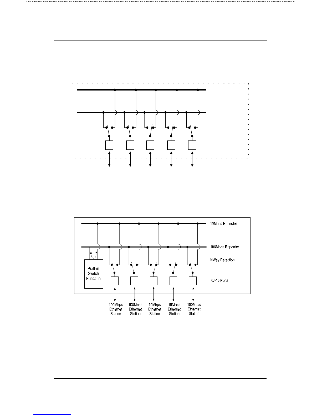
A dual-speed hub is actually two repeaters in one enclosure. The 10Mbps
repeater receives Ethernet transmissions from any of its ports, and retransmits them to all other ports operating at 10Mbps. Similarly, the 100Mbps
Page 16
Introduction4
repeater retransmits Fast Ethernet transmissions from ports operating at
100Mbps to all other ports operating at the same speed.
10M b ps R epeater
100Mbps Repeater
NWay Detection
RJ-45 Ports
100Mbps
Ethernet
Station
100Mbps
Ethernet
Station
10Mbps
Ethernet
Station
10Mbps
Ethernet
Station
100Mbps
Ethernet
Station
If there is a DFE-908x hub present in the stack, its built-in switch serves as
a bridge between t he two inde pe ndent segm ent s.
Page 17

Dual-Speed Stackable Hubs User’s Guide
Introduction 5
100BASE-TX Technology Overview
100Mbps Fast Ethernet Introduction
Computers today have become increasingly powerful, with the capability to
accommodate very sophisticated uses such as multimedia applications,
video-conferencing, and CAD/CAM. To utilize these technologically advanced applications more efficiently, there is also a growing demand for
faster networks that ca n ha ndle he avy ne t work traffi c .
Recognizing this need for greater bandwidth and lower latency, a variety of
technologi es such as FDDI, ATM, and Fast Ethe rnet (100Mbps) have be en
adopted by many vendors. Fast Ethernet technology stands out as the most
inexpensive and smoothest migration path for existing 10Mbps Ethernet
users in part because it does not require a protocol translation when sharing
data with 10Mbps Ethernet.
Fast Ethernet is a relatively new standard specified by the IEEE 802.3 LAN
committee. It is an extension of the 10Mbps Ethernet standard with the
ability to transmit and receive data at 100Mbps, while maintaining the
CSMA/CD Ethernet protocol. Since Fast Ethernet is compatible with all
10Mbps Ethernet environme nts, it provi des a straightforward upgrade without wasting the company’s existing investment in hardware, software, and
trained personnel.
Cables and Connectors
Category 5 unshielded twisted-pair (UTP) cables and shielded twisted-pair
(STP) cables are both supported. Cat 5 UTP cable uses the same RJ-45
connector used with 10BASE-T, wired in the same configuration. Please
note that the punch-down blocks in the wiring closet must also be Category
5 certified. Where these blocks do not meet the standard, an upgrade is
necessary.
Page 18

Introduction6
Topology
A Fast Ethernet workgroup is configured in a star topology and is built
around a maximum of two repeaters. Each workgroup forms a separate
LAN (also known as a segment or collision domain), and these workgroups
can be easily interconnected through switches, bridges, or routers to form
one LAN large enough to encompass a high-rise building or campus environment. Recent innovations in LAN hub technology such as stackable
hubs, coupled with the decreasing cost of switches, bridges, and routers,
allow the design of low-cost, efficient Fast Ethernet workgroups and enterprise LANs.
The following factors strongly influence the architecture of Fast Ethernet
networks:
•
The EIA/TIA 568 Wiring Standard imposes a 100 meter limit on
horizontal runs of twisted-pair cables; that is, connections from the
wiring closet to the end-station.
•
Fast Ethernet’s increased operational speed reduces the maximum
distance between all elements of the LAN (see below).
•
The EIA/TIA 568 Wiring Sta ndard does not support the use of coaxial cables for horizontal wiring.
Network Diameter
Network diameter, which is the distance between two end-stations in the
same collision domain, is the primary difference between traditional
Ethernet and Fast Ethernet. Due to the increased speed in Fast Ethernet and
adherence to the EIA/TIA 568 wiring rules, the network diameter of a Fast
Ethernet collision domain is limited to 205 meters; in contrast, the maximum 10BASE-T Ethernet collision domain diameter can be up to 500
meters.
Page 19

Dual-Speed Stackable Hubs User’s Guide
Unpacking and Setup 7
Hub Types
Unlike 10BASE-T hubs, which are all functionally identical, Fast Ethernet
hubs are divided into t wo disti nct t ypes: Cl a ss I and Class II. A Cla ss I hub
repeats all incoming signals on one port to the other ports by first translating them to digital signals and then retranslating them back to line signals.
These translations are necessary when connecting various network media to
the same collision domain, such as when combining two wire-pair
100BASE-TX media with four wire-pair 100BASE-T4 media. Only one
Class I hub can exist within the same collision domain; thus, this type of
hub cannot be directly interlinked. A Class II repeater, on the other hand,
immediately repeats all incoming line signals on one port to the other ports;
no translations are performed. This type of hub connects identical media
within the same collision domain; for example, TX to TX. At most, two
Class II hubs can exist within the same collision domain.
As mentioned earlier, stackable Class II hubs can be used to increase the
number of available nodes in a collision domain. An entire hub stack
counts as a single repeater. DFE-908 series hubs are Class II devices.
2
2 U
NPACKING AND
S
ETUP
This chapter provides information on the unpacking and initial installation
of your hub stack.
Page 20
Unpacking and Setup8
Unpacking
Open the shipping carton of your hub and carefully unpack the contents.
The carton should contain the following items:
♦
One dual-speed stackable hub
♦
One AC power cord, suitable for your area’s electrical power connections
♦
One daisy-chain cable
♦
Four rubber feet to be used for shock cushioning
♦
This
User’s Guid e
Inspect the hub and all accompanying items. If any item is damaged or
missing, report the problem immediately to your D-Link dealer.
Identifying External Components
This section identifies all the major external components of the hub. Both
the front and rear panels are shown, followed by a description of each panel
feature. The indicator panel is described in detail in the next chapter.
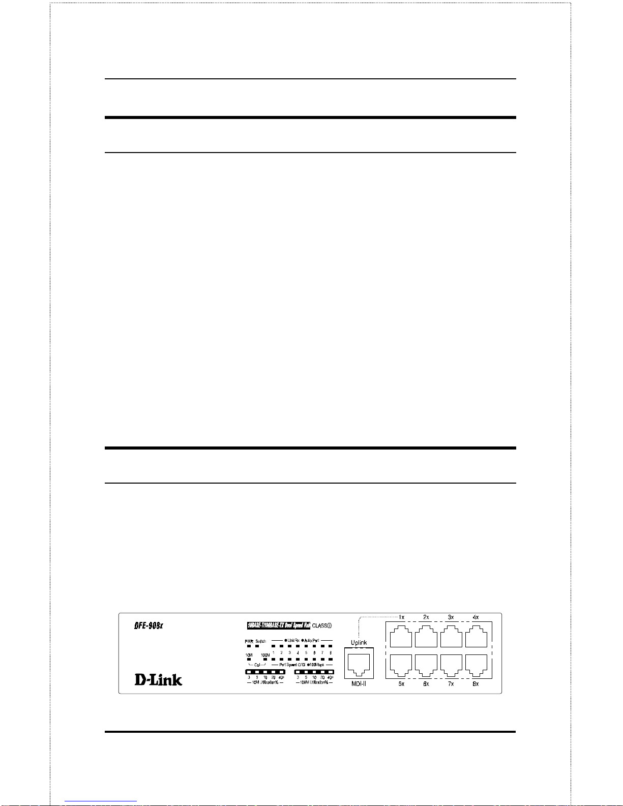
Front Panel
Page 21
Dual-Speed Stackable Hubs User’s Guide
Unpacking and Setup 9
♦ LED Indicator Panel
Refer to the next chapter,
Understanding Indicators
, for detailed infor-
mation about each of the hub’s LED indicators.
♦ Twisted-Pair Ports
Use any of these ports to connect stations to the hub. The ports are
MDI-X ports, which means you can use ordinary straight-through
twisted-pair cable to connect the hub to PCs, workstations, or servers
through these ports. If you need to connect to another device with MDIX ports such as another hub or an Ethernet switch, you should use a
crossover cable, or connect using the Uplink port (described below).
For more information about crossover connection, see the
Crossover
Cables
section on page 24.
♦ Uplink Port
The Uplink port is an MDI port, which means you can connect the hub
(or hub stack) to another device with MDI-X ports using an ordinary
straight-through cable, making a crossover cable unnecessary.
Port 1 and the Uplink port are really the same port, except that their
pinouts are different.
Do not use bot h Port 1 and the Uplink port at
the same time.
Page 22
Unpacking and Setup10
Rear Panel
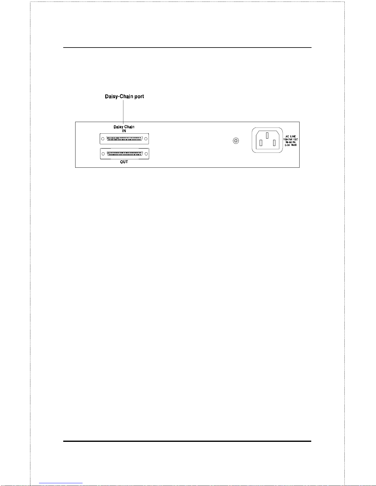
♦ Daisy- Chain IN Port
When cascading a set of D-Link’s stackable dual-speed hubs, this port
should be connected to the Daisy-Chain OUT port of the previous hub
in the stack (usually placed immediately above it). A cascade of five
hubs can be created in this way. The first and last hubs in the stack use
only one of the daisy-chain ports, while the others use both.
♦ Daisy-Chain OUT Port
Works in conjunction with the Daisy-Chain IN Port (see above). Connect this port to the Daisy-Chain IN Port of the next hub in the stack
(usually placed immediately below it), using the enclosed daisy-chain
cable.
♦ Fan
Provides air circulation and heat dissipation. Be sure to leave adequate
space around the area of the unit for proper ventilation.
♦ AC Power Connec t o r
For the power cord.
Page 23

Dual-Speed Stackable Hubs User’s Guide
Unpacking and Setup 11
Installing the Hub
Installation
The site where you install the hub stack may greatly affect its performance.
When installing, consider the following pointers:
♦
Install the hub stack in a fairly cool and dry place. See Appendix B,
Specifications
, for the acceptable temperature and humidity operat-
ing ranges.
♦
Install the hub stack in a site free from strong electromagnetic field
generators (such as motors), vibration, dust, and direct exposure to
sunlight.
♦
Leave at least 10cm of space at the front and rear of the hub for
ventilation.
♦
Install the hub on a sturdy, level surface that can support its weight.
When installing the hub stack on a level surface, attach the rubber feet to
the bottom of each device. The rubber feet cushion the hub and protect the
hub case from scratches and prevent it from scratching other surfaces.
Page 24
Understanding Indicators12
3
3 U
NDERSTANDING
I
NDICATORS
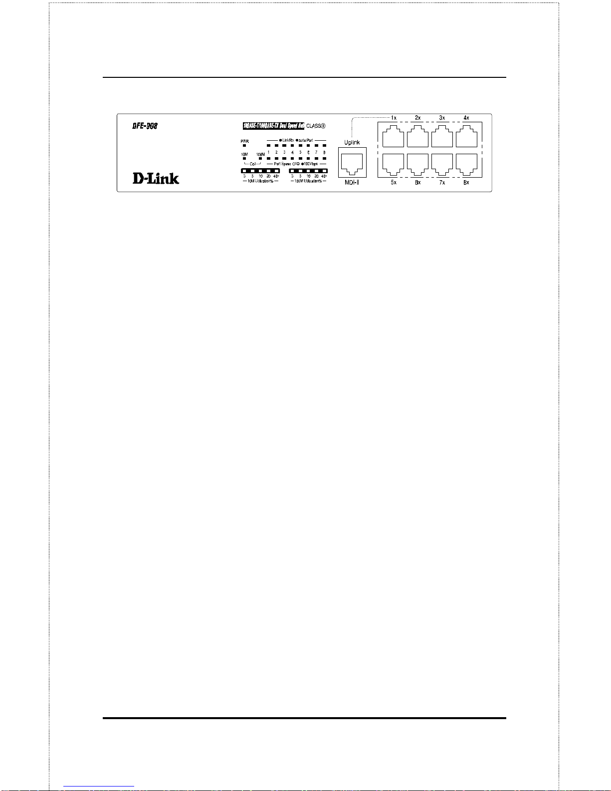
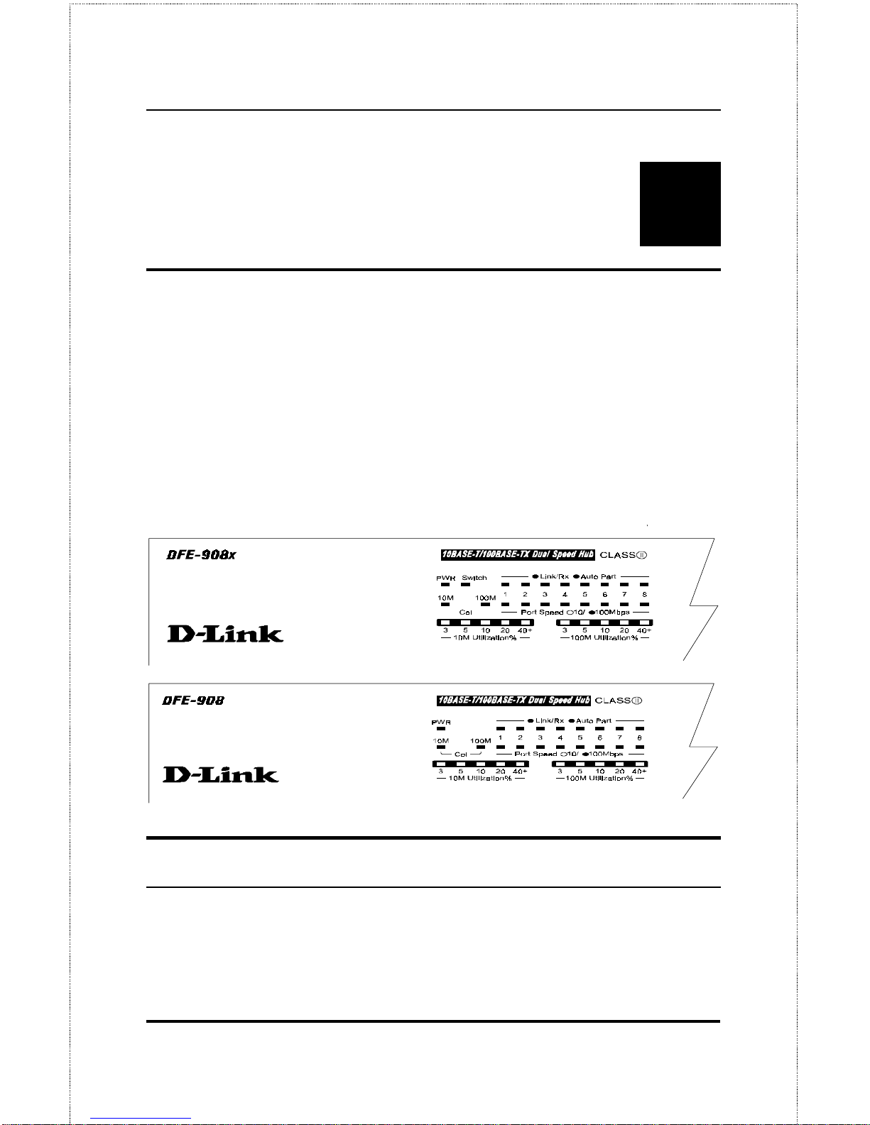
Before connecting network devices to the hub, take a few minutes to look
over this section and familiarize yourself with the front panel LED indicators of your dual-speed hub, depicted below.
Hub State Indicators
♦ Power Indicator (PWR)
Page 25

Dual-Speed Stackable Hubs User’s Guide
Understanding Indicators 13
This indicator lights green when the hub is receiving power; otherwise,
it is off.
♦ Collision Indicators (Col 10M/ Col 100M)
These indicators indicate data collisions on the respective 10Mbps
Ethernet or 100Mbps Fast Ethernet segments connected to the hub. (If
several hubs are stacked or linked together, all of them should detect
and indicate the same collision, since collisions span the entire network
segment.) Whenever a collision is detected, the respective COL indicator will briefly blink amber.
♦ 10Mbps and 100Mbps Utilization Indicators
The utilization bar graphs provide a quick reference on the current traffic load relative to the total available 10Mbps or 100Mbps network
bandwidth. The graphs display a measure of the percentage of bandwidth in use on the respective network segment. All data packets are
counted, whether valid or not.
Port State Indicators
There is one port state indicator for each of the twisted-pair ports on the
hub. Each port’s LED status indicator reports the port’s link and activity
status, and shows whether or not the port has been partitioned.
The following describes each indicator and the meaning of each condition:
♦ Link (steady green)
The indicator of a port lights green when the port is connected to a powered Ethernet or Fast Ethernet station. If the station to which the hub is
connected is powered off, or if there is a problem with the link, the LED
will remain off.
Page 26

Understanding Indicators14
♦ Receive (Rx) (blinking green)
When information is received on a port, its indicator will blink off
briefly. Upon reception, the data will be transmitted to all other connected ports.
♦ Auto-partition (Auto-part) (steady amber)
The indicator of a port lights amber when the port is automatically partitioned due to an abnormal network condition.
The hub will temporarily partition a port when too many collisions are
detected on the port. While the segment is automatically partitioned,
the port will be isolated from the rest of the network segment. When
the problem is corrected or a valid data packet is received through the
port, the port is automatically reconnected.
Port Speed Indicators
There is also a port speed indicator for each of the twisted-pair ports on the
hub. A port’s speed indicator should light green when a 100BASE-TX device is connected to the port, and remain dark if the port is unconnected or
if a 10BASE-T device is connected.
Switch Indicator (DFE-908x Only)
The DFE-908x’s Switch indicator shines a steady green when the hub’s
built-in switch is functioning correctly. The indicator should shine whenever the hub has power.
Page 27

Dual-Speed Stackable Hubs User’s Guide
Understanding Indicators 15
Page 28

Page 29

Dual-Speed Stackable Hubs User’s Guide
Making Connections 17
4
4 M
AKING
C
ONNECTIONS
This chapter discusses how to make connections to the hub’s twisted-pair
ports, cascading hubs to create a stack, and linking with other hubs (or hub
stacks).
Hub Cascading/Building a Stack
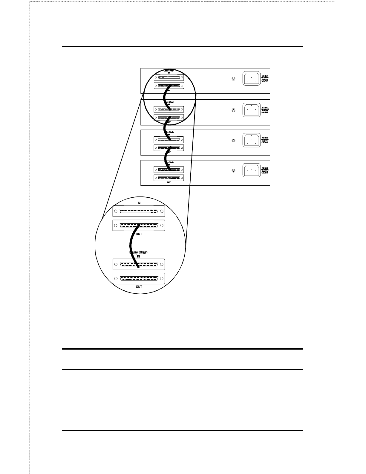
You can stack up to five hubs using the daisy-chain ports to form one logical hub. In this configuration, the interconnected hubs constitute a single
logical unit, providing a maximum of 40 twisted-pair ports.
Use the provided daisy-chain cable to connect the Daisy-Chain OUT port
on the rear panel of one hub to the Daisy-Chain IN port on the hub bel ow
it, as shown in the figure below. Repeat this procedure for each hub to be
included in the stack.
Page 30
Making Connections18
Hubs should not be added to the stack or removed from the stack while the
power is on to any hub in the stack. Always turn off power to the entir e
stack before addi ng or r e movi ng hubs.
Connectivity Rules
Ethernet (10Mbps) networks need to respect the following connectivity
rules:
Page 31

Dual-Speed Stackable Hubs User’s Guide
Making Connections 19
♦ The maximum length of a twisted-pair cable segment is 100 meters.
Cabling should be Category 3 or better.
♦ Between any two end-stations in a collision domain, there may be up
to five cable segments and four intermediate repeaters (hubs, hub
stacks, or other repeaters).
♦ If there is a path between any two end-stations containing five seg-
ments and four repeaters, then at least two of the cable segments
must be point-to-point link segments (e.g., 10BASE-T, 10BASEFL), while the remaining segments may be populated (mixing) segments (e.g., 10BASE-2 or 10BASE-5).
Fast Ethernet (100Mbps) networks need to respect the following connectivity rules:
♦ The maximum length of a twisted-pair segment (that is, the distance
between a port in the hub to a single-address network device such as
a PC, server, or Ethernet switch) is 100 meters. Cabling and other
wiring should be certified as Category 5 or shielded twisted pair
(STP).
♦ The maximum diameter in a collision domain is about 205 meters
using two Class II hubs (or hub stacks).
♦ Between any two end-stations in a collision domain, there may be up
to three cable segments and two Class II hubs or hub stacks.
Hub to End-Station Connection
After the hub properly installed, it can support up to eight end-station connections. Fast Ethernet connection requires either a Category 5 UTP cable
or an STP cable. These cables can be up to 100 meters long.
Page 32
Making Connections20
Ethernet connection requires a Category 3 or better UTP cable. It is recommended that you use Category 5 cabling for all connections, in order to
make it easier to transition all stations to 100Mbps.
You can connect any combination of PCs, servers, and other single-address
network devices to the eight twisted-pair ports using straight-through
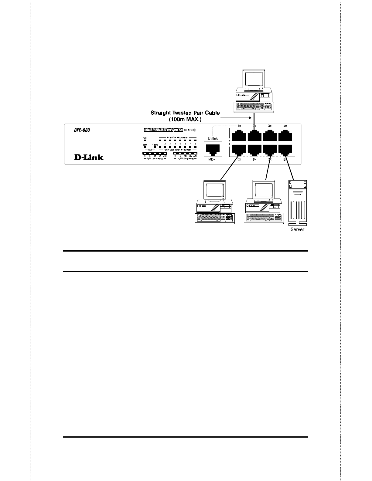
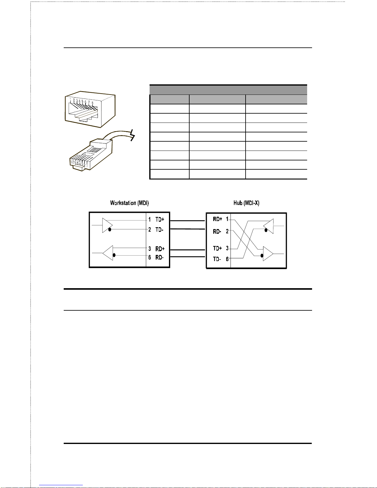
twisted-pair cabl es. These cable s should not be crossed over. The following figure illustrates the pin assignments for a straight-through cable:
When connecting a PC or a server, the system being connected should have
an Ethernet or Fast Ethernet network interface card with a twisted-pair port.
The following figure shows a typical connection between the hub and endstations:
Page 33
Dual-Speed Stackable Hubs User’s Guide
Making Connections 21
Hub-to-Hub Uplink
You can link two hubs or hub stacks to each other using any of the twistedpair ports or the Uplink port. Linking hubs using ordinary twisted-pair
ports requires crossover twisted-pair cables; linking using one ordinary
twisted-pair port and the Uplink port requires an ordinary stra ight-through
twisted-pair cabl e. The Uplink port is shared with Port 1, and you should
not use both Port 1 and the Uplink port at the same time.
When connecting two hubs or hub stacks in this fashion, the maximum
distance between any two end-stations in a collision domain is 205 meters.
If each link between the hub and an end-station is 100 meters, then the hubto-hub connection is limited to 5 meters. However, if the longest hub-toend-station connection is less than 100 meters, then the hub-to-hub connection can be up to 100 meters long as long as the 205-meter total network
diameter rule is followed.
Page 34
Making Connections22
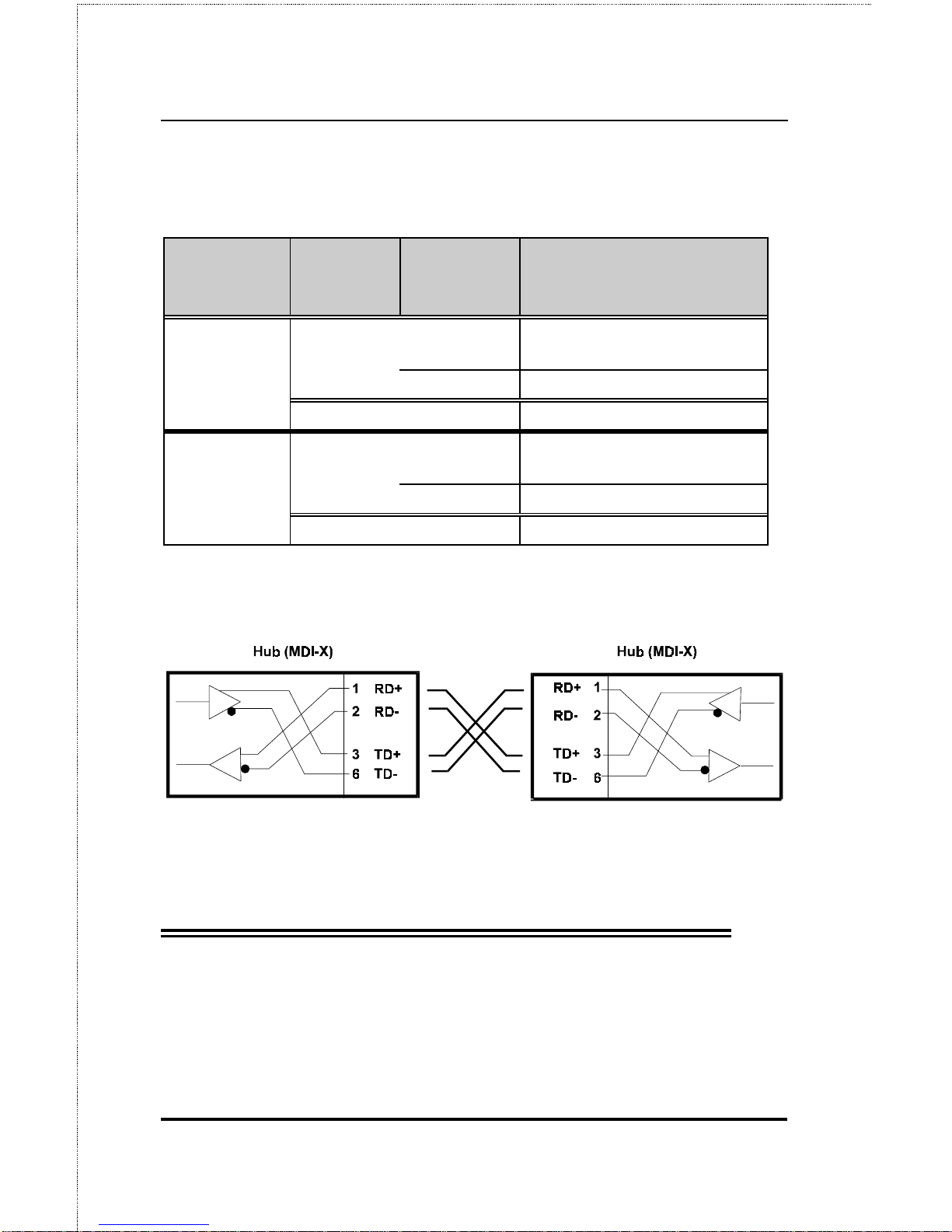
The following table describes different methods of linking hubs (or hub
stacks):
HUB
PORT
USED
DEVICE PORT
TYPE
CABLE TO US E
Normal Switch or
Hub
NonUplink
Crossover (X)
Uplink
Strai ght-Through (| | )
Server (or PC) Strai ght-Through (| | )
Uplink
Switch or
Hub
NonUplink
Strai ght-Through (| | )
Uplink
Crossover (X)
Server (or PC) Crossover (X)
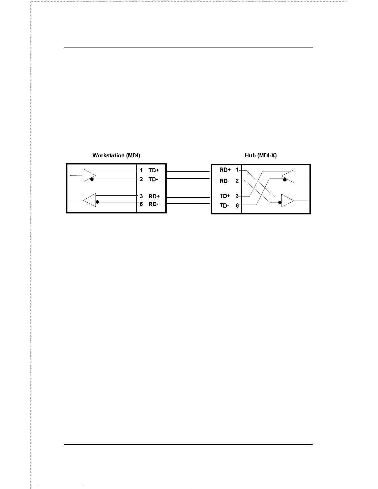
A crossover cable is a straight-through twisted-pair cable in which the
wires have been crossed. T he figure below shows the pin assignments for
an Ethernet or Fast Ethernet crossover cable:
NOTE:
The first twisted-pair port (Port 1) is shared
with the Uplink port. If you connect a hub to
the Uplink por t, then do not us e Por t 1.
Page 35

Dual-Speed Stackable Hubs User’s Guide
Cables and Connectors 23
A
5 C
ABLES AND
C
ONNECTORS
100BASE-TX Ethernet Cable and
Connectors
♦ Cable characteristics: 0.4 to 0.6 mm (22 to 26 AWG) 4-pair (only
two pairs or four wires are used for 100BASE-TX); Category 5 unshielded twisted-pair or EIA/TIA-568 compliant, 100-ohm shielded
twisted-pair
♦ Maximum segment length: 100 meters
♦ Maximum network diameter: 205 meters
♦ Connector: RJ-45
Page 36
Cables and Connectors24
Contact MDI - X Signal MDI Signal
1 RD+ (receive) TD+ (transmit)
2 RD- (receive) TD- (transmit)
3 TD+ (transmit) RD+ (receive)
4 Not used Not used
5 Not used Not used
6 TD- (transmit) RD- (receive)
7 Not used Not used
8 Not used Not used
Crossover Cables
When cascading or connecting the hub to another switch, bridge, or hub
through the UTP port, a modified crossover cable is necessary. With a
crossover cable, two pairs of wires are switched at one connector end.
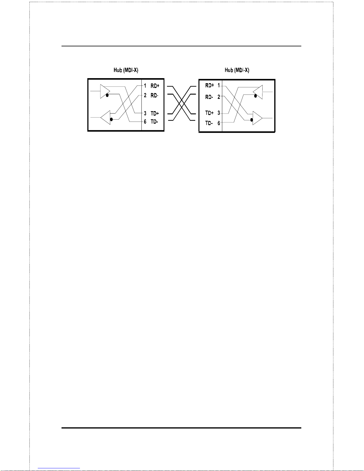
Carry out the following steps to create a customized, crossover twisted-pair
cable:
1.
Leave one end of the cable as is, with the RJ-45 connector intact.
The wiring at just one end of the cable needs to be modified.
2.
At the other end of the cable, connect wires 1 and 2 to contacts 3
and 6, respectively. Likewise, connect wires 3 and 6 to contacts 1
and 2. Refer to t he fol l owing dia gra m:
Page 37
Dual-Speed Stackable Hubs User’s Guide
Cables and Connectors 25
Page 38

Specifications26
B
6 S
PECIFICATIONS
General
Standards: IEEE 802.3 10BASE-T Ethernet repeater
IEEE 802.3u 100BASE-TX Fast Ethernet repeater (Class II)
ANSI X3T9. 5 T wisted- Pa i r T r a n sceiver
Topology: Star
Protocol: C SMA/ C D
Network Data Transfer Rate: Ethernet: 10Mbps;
Fast Ethernet: 100 Mbps
Number of Ports per Hub: 8, all dual-speed (10Mbps/100Mbps)
Network Ca bl es:
10BASE-T: 2-pair UTP Cat. 3, 4, 5 (100 m); EIA/TIA-568 100-ohm
screened twisted-pai r (STP) (100 m)
100BASE-TX: 2-pair UTP cat. 5 (100 m); EIA/TIA-568 100-ohm screened
twisted-pair (STP) (100 m)
Hub-to-Hub Cascading
Number of Da i sy -Cha i ned Hubs: Maximum of 5 hubs per stack
Page 39

Specifications 27
Daisy-Chain Port: MiniSCSI-type connector × 2
Daisy-Chain Cable: SCSI-type cable (supplied)
LED Indicators
Hub Status: Power, 10Mbps collision, 100Mbps collision, 10Mbps utili-
zation, 100Mbps utilization
Port Status (per port): Link/Receive/Auto Partition, Speed (10/100Mbps)
Environmental and Physical
Power Suppl y :
100 to 240 VAC, 50 or 60 Hz internal uni versal power supply
Power Co nsumpt i o n:
DFE-908x: 10 watts max.; DFE-908: 10 watts max.
Dimensions: 233mm × 141mm × 44mm (9.2 × 5.6 × 1.7 inches)
Weight: 1.2 kg (2.6 lb)
Operating Temperature: -10° to 55°C (14°-131°F)
Storage Temperature: –25° to 55°C (-13°-131°F)
Humidity: 5% to 95% non-condensing
DC Fan: 40mm × 40mm DC Fan × 1
Emissions: FCC Class B, CE Mark, VCCI Class B, C-Tick
Safety: UL (UL 1950); CSA (CSA 950); TÜV/GS (EN60950)
Page 40

Page 41

Offices
U.S.A. D-LINK SYSTEMS, INC.
5 Musick Irvine, CA 92618 USA
TEL: 1-714-455-1688 FAX : 1-714-455-2521
CANADA D-LINK CANADA, INC.
2180 Dunwin D rive, Unit # 6,
Missi ssauga Ontario, L5L 5M8, C anada
TEL: 1-905-828-0260 FAX : 1-905-828-5669
U.K. D-LINK (EUROPE) LTD.
D-Link House, 6 Garland Road, Stanmore, London HA7 1DP U. K.
TEL: 44-181-2355555 FAX: 44- 181-2355500
GERMANY D-LINK (DEUTSCHLAND) GMBH I.G.
Bachstrae 22, 65830 Kri ftel, Germ any
TEL: 49-6192-97110 FAX: 49- 6192-971111
FRANCE D-LINK FRANCE
Le FLORILEGE #2, Allee de la Fresnerie
78330 Fontena y L e Fleury F rance
TEL: 33-1-30238688 FAX: 33-1- 30238689
SWEDEN D-LINK A / B
World Trade Ce nter P. O. Box 70396, 107 24 S t ockholm Sw eden
TEL: 46-8-7006211 FAX: 46-8- 219640
DENMARK D-LINK DENMARK
Nave rland 2 DK-908 Glost rup Copenha gen, De nmark
TEL:45-43-969040 FAX:45-43-424347
SINGAPORE D-LINK SINGAPORE PTE.LTD.
77 Scie nce Park Drive #03-03 CINTE CH III,
Singapore Scie nce Park Singapore 118256
EL : 65-7746233 FA X: 65-7746322
AUSTRALIA D-LINK AUSTRALIA PTY.LTD.
Unit 16, 390 Eastern Val l ey Way Roseville, N SW 2069 Austra l i a
TEL: 61-2-94177100 FAX: 61-2- 94171077
CHINA D-LINK BEIJING
15th Floor, S cienc e & Te chnology Towe r
No. 11, Baishiqi ao Road, Haidian District Beijing 100081, C hi na
TEL: 86-10-68467106 FAX: 86-10-68467110
JAPAN D-LINK TOKYO
10F, 8-8-15 Nishigotanda, Shinagawa-ku Tokyo 141 Ja pan
TEL: 81-3-5434-9678 FAX: 81- 3-5434-9868
INDIA D-LINK (INDIA) PVT. LTD.
Bombay Office : Plot No.5, Kurla-Bandra Complex Rd.
Off C st Rd., S antac ruz (E) Bombay - 400 098 India
TEL: 91-22-6172478 FAX: 91-22-6172476
TAIWAN D-LINK TAIWAN
2F, No. 233-2 Pao-Chi ao Rd, H sin-Tien, Taipei,Taiwan, R.O.C.
TEL: 886-2-916-1600 FAX: 886-2-914-6299
Page 42

Page 43
Registration Card
Print, type or use block letters.
Your name: Mr./Ms_____________________________________________________________________________
Organization: ________________________________________________Dept. ____________________________
Your title at organization:________________________________________________________________________
Telephone:_______________________________________ Fax:________________________________________
Organization's full address: ______________________________________________________________________
____________________________________________________________________________________________
Country: _____________________________________________________________________________________
Date of purchase (Month/Day/Year): _______________________________________________________________
3URGXFW 0RGHO 3URGXFW 6HULDO
1R1
- 3URGXFW LQVWDOOHG LQ W\SH RI
FRPSXWHU +H1J1/ &RPSDT 7;9,
- 3URGXFW LQVWDOOHG LQ
FRPSXWHU VHULDO 1R1
(* Applies to adapters only)
Product was purchased from:
Reseller's name: ______________________________________________________________________________
Telephone:_______________________________________ Fax:________________________________________
Reseller's full address: _________________________________________________________________________
_________________________________________________________________________
_________________________________________________________________________
Answers to the following questions help us to support your product:
1. Where and how will the product primarily be used?
†
Home †Office †Travel †Company Business †Home Business †Personal Use
2. How many employees work at installation site?
†
1 employee †2-9 †10-49 †50-99 †100-499 †500-999 †1000 or more
3. What network protocol(s) does your organization use ?
†
XNS/IPX †TCP/IP †DECnet †Other_____________________________
4. What network operating system(s) does your organization use ?
†
D-Link LANsmart †Novell NetWare †NetWare Lite †SCO Unix/Xenix †PC NFS †3Com 3+Open
†
Banyan Vines †DECnet Pathwork †Windows NT †Windows NTAS †Windows '95
†
Other__________________________________________
5. What ne twork management program does your organization use ?
†
D-View †HP OpenView/Windows †HP OpenView/Unix †SunNet Manager †Novell NMS
†
NetView 6000 †Other________________________________________
6. What ne twork medium/media does your organization use ?
†
Fiber-optics †Thick coax Ethernet †Thin coax Ethernet †10BASE-T UTP/STP
†
100BASE-TX †100BASE-T4 †100VGAnyLAN †Other_________________
7. What applications are used on your network?
†
Desktop publishing †Spreadsheet †Word processing †CAD/CAM
†
Database management †Accounting †Other_____________________
8. What category best describes your company?
†
Aerospace †Engineering †Education †Finance †Hospital †Legal †Insurance/Real Estate †Manufacturing
†
Retail/Chainstore/Wholesale †Government †Transportation/Utilities/Communication †VAR
†
System house/company †Other________________________________
9. Would y ou recommend your D-Link product to a friend?
†
Yes †No †Don't know yet
10.Your comme nts on this product?
__________________________________________________________________________________________
__________________________________________________________________________________________
Page 44
 Loading...