

Page 1
10/100 Ethernet PC Card
for CardBus
Model DFE-660TX
User’s Guide
Rev. 01 (November, 1997)
6DFE660.01
Printed in Taiwan
RECYCLABLE
Page 2

Page 3

Trademarks
Copyright D-Link Corporation.
Contents subjected to revision without prior notice.
D-Link is a registered trademark of D-Link Corp oration / D-Link Systems,
Inc. All other trademarks belong to their owners.
Copyright Statement
No part of this publication may be reproduced in any form or by any means
or used to make any derivative (such as translation, transformation or
adaptation) without permission from the D-Link Corporation / D-Link
Systems Inc., as stipulated by the United States Copyright Act of 1976.
FCC Warning
DFE-660TX FCC Class B ID KA2FEPC66001
This equipment has been tested and found to comply with the limits for a
Class B digital device, pursuant to Part 15 of the FCC Rules. These limits
are designed to provid e reason ab le pr otect io n agai nst h armful int erference in
a residential installation. This equipment generates, uses and can radiate
radio frequency energy and, i f not instal led and u sed in accordance with th e
instructions, may cause harmful interference to radio communications.
However, there is no guarantee that interference will not occur in a
particular installation. If this equipment does cause harmful interference to
radio or television reception, which can be determined by turning the
equipment off and on, the user is encouraged to try to correct the
interference by one or more of the following measures:
• Reorient or relocate the receivi ng antenna.
• Increase the separatio n between the equipment and receiver.
• Connect the equipment into an outlet on a circuit different from that to
which the receiver is connected.
• Consult the dealer or an experienced radio /TV technician for help.
Shielded interface cables must be used in order to comply with emission
limits.
You are cautioned that changes or modifications not expressly approved by
the party responsible for compliance could void your authority to operate the
equipment.
Page 4

This device complies with Part 15 of the FCC rules. Operation is subject to
the following two conditions: (1) This device may not cause harmful
interference, and (2) This device must accept any interference received,
including interference that cause undesired operation.
LIMITED WARRANTY
Hardware:
D-Link warrants its hardware products to be free from defects in
workmanship and materials, under normal use and service, for the following
lengths of time from the date of purchase from D-Link or its authorized
reseller:
Product Ty pe Warranty Period
Network adapters Lifetime
Unmanaged and managed hubs* Lifetime
Repeaters, MAUs, transceivers, media converters One year
Concentrators One year
Internetworking products One year
Other hardware products One year
Spare parts and spare kits 90 days
* Power supply and fans in these devices One year
If a product does not operate as warranted during the applicable warranty
period, D-Link shall, at its option and expense, (1) repair the defective
product or part, (2) deliver to Customer an equivalent product or part to
replace the defective item. All products that are replaced will become the
property of D-Link. Replacement products may be new or reconditioned.
Any replaced or repaired product or part has a ninety (90) day warranty or
the remainder of the initial warranty period, whichever is longer.
D-Link shall not be responsible for any software, firmware, information, or
memory data of Customer contained in, stored on, or integrated with any
products returned to D-Link pursuant to any warranty.
All products with lifetime warranty have a standard five-year warranty. To
qualify for lifetime warranty, the enclosed Product Registration Card must
be completed and returned to D-Link within ninety (90) days of purchase.
Page 5

Warranty service may be obtained by contacting a D-Link office for a Return
Material Authorization (RMA) number. See list of office locations at the
end of this manual. If a Product Registration Card has not been previously
sent, proof of purchase, such as a copy of the dated purchase invoice, must
be provided. Once an RMA number is issued, the defective product must be
shipped back to D-Link prepaid, insured and wrapped in the original or
similar shipping package to ensure that it will not be damaged during
shipment. When returning the defective product to D-Link for service, the
RMA number must be marked on the outside of the shipping package. Any
product returned without an RMA number shall be rejected and sent back to
the Customer, and D-Link reserves the righ t to have Custo mer bear the cost
of sending back such products. A service charge may or may not be levied
to Customer by D-Link. To find out if a service charge is levied or not, and
the charged amount, read the RMA that is returned to Customer, or ask the
D-Link office when an RMA is requested .
Software
D-Link warrants that the software programs licensed from it will perform in
substantial conformance to the applicable published program specifications
for a period of ninety(90) days from the date of purchase from D-Link or its
authorized reseller. D-Link warrants the magnetic media containing software
against failure during the warranty period. No updates are provided.
D-Link‘s sole obligation hereunder shall be to replace any defective software
products with products which substantially conform to D-Link’s applicable
published specifications. Customer assumes responsibility for the selection
of the appropriate applications program and associated reference materials.
D-Link makes no warranty that its software products will work in
combination with any hardware of applications software products provided
by third party, that the operation of the software products will be
uninterrupted or error free, or that all defects in the software product will be
corrected. For any third party products listed in the D-Link software product
documentation or specifications as being compatible. D-Link will make
reasonable efforts to provide compatibility, except where the noncompatibility is caused by “bug” or defect in the third party‘s product.
Warranty service for software products may be obtained by contacting a
D-Link office within the warranty period. See list of office locations at the
end of this manual. Where no Product Registration Card has been sent by
Customer, proof of pu rchase, su ch as a cop y of the dat ed p urchased in voice,
must be provided.
Page 6

WARRANTIES EXCLUSIVE
If the D-Link product does not operate as warranted above, the
customer's sole remedy shall be, at D-Link's option, repair or
replacement. The foregoing warranties and remedies are
exclusive and are in lieu of all other warranties, expressed or
implied, either in fact or by operation of law, statutory or
otherwise, including warranties of merchantability and fitness
for a particular purpose. D-Link neither assumes nor
authorizes any other person to assume for it any other liability
in connection with the sale, installation maintenance or use of
D-Link's products.
D-Link shall not be liable under this warranty if its testing and
examination disclose that the alleged defect in the product does
not exist or was caused by the customer's or any third person's
misuse, neglect, improper installation or testing, unauthorized
attempts to repair, or any other cause beyond the range of the
intended use, or by accident, fire, lightning or other haz ard.
LIMITATION OF LIABILITY
In no event will D-Link be liable for any damages, including loss
of data, loss of profits, cost of cover or other incidental,
consequential or indirect damages arising out the installation,
maintenance, use, performance, failure or interruption of a D- Link
product, however caused and on any theory of liability. This
limitation will apply even if D-Link has been advised of the
possibility of such damag e.
If you purchased a D-Link product in the United States, some
states do not allow the limitation or exclusion of liability for
incidental or consequential damages, so the above limitation may
not apply to you.
Page 7

Table of Contents
1.
INTRODUCTION
............................................................. 1
General Description ............................................... 1
About Fast Ethernet ..................................................... 2
About Autonegotiation .................................................. 3
LED Indicators............................................................... 5
Summary of Features .................................................. 5
2. HARDWARE INSTALLATION
...................................... 7
Unpack and Inspect...................................................... 7
Hardware Installation ................................................... 8
Remove the PC Card.................................................11
Connect the Network Cable...................................... 13
Connecting for Fast Ethernet ...................................13
Connecting for 10Mbps Ethernet.............................13
3. SOFTWARE INSTALLATION
.....................................15
Run Installation Director.......................................15
Installing 16-bit NetWare Client for Dos.................17
A. TROUBLESHOOTING
................................................17
Troubleshooting t he Har dware Inst allation.............17
Troubleshooting t he Software Installation .............. 17
B. DFE-660TX SPECIFICATIONS
.................................20
Page 8

Page 9
1
Introduction
Thank you for choosing D-Link DFE-660TX, the value leader
among Ethernet / Fast Ethernet adapters for CardBus notebook PCs.
This chapter provides a general description of DFE-660TX features,
with a summary of features at the end of the chapter. Installation
instructions are given in Chapters 2 and 3.
General Description
The D-Link DFE-660TX 10/100 Ethernet PC Card for CardBus
notebook PCs is a credit-card sized Ethernet / Fast-Ethernet adapter
for connecting a notebook PC to an IEEE 802.3 or 802.3u Ethernet
network. The notebook PC must be equipped with CardBus (32 bit)
extension bus and Type II or Type III PC Card slot (s).
NOTE:
The terms "PC Card" and “CardBus” are used throughout
this manual to refer to those objects as defined in the
PCMCIA / PC Card standards published by Personal
Computer Memory Card Industry Association (PCMCIA).
The term “slot” is used in this manual is synonymous with
“socket” where the standards use the latter term in
reference to the physical receptacles of a host notebook
computer, for insertion/connection of PC Cards. More
information on the standards is available from PCMCIA’s
www server at http://www.pc-card.com.
The DFE-660TX automatically detects the parameters of its Ethernet
environment, and automatically negotiates and determines its own
speed and duplex settings as required for maximum performance in
Page 10

DFE-660TX Fast Et hernet PC Card User's Guide
2
Introduction
its environment. (The autonegotiation function is effective only
when the DFE-660TX is connected to the network by a device
(switch or hub) which also has autonegotiation functionality.)
Inside its compact case, the D-Link DFE-660TX holds an Ethernet
controller, network processing interface, a 68-pin PC Card Standard
front-end plug which connects to the notebook PC, and a 15-pin
back-end receptacle for connecting the media coupler. The
DFE-660TX requires no pre-installation setup -- simply insert its
front end into the notebook PC's PC-Card slot.
The DFE-660TX is supplied with a media coupler which plugs into
the back end (15-pin receptacle) of the DFE-660TX. The other end
of the media coupler has an RJ-45 receptacle which receives the
network cable. The media coupler features LED indicators for
linkage and activity states, and for the speed and duplex settings.
About Fast Ethernet
Fast Ethernet is a network technology specified by IEEE Standard
802.3u. It extends the traditional 10Mbps (10 megabit/sec) Ethernet
technology to achieve 100Mbps (100 megabit/sec) transmission and
reception. Because Fast Ethernet retains the traditional Ethernet
CSMA/CD (Carrier Sense, Multiple Access, Collision Detect)
protocol, it remains wholly compatib le with 10Mbps Ethernet while
providing a tenfold increase in network capacity.
The Fast Ethernet standard specifies three subtypes, corresponding
to three media types:
100Base-TX (using two twisted pairs in EIA 568 Category 5
UTP or STP cable)
100Base-T4 (using four twisted pairs in a Category 3,
Category 4, or Category 5 UTP cable)
Page 11

DFE-660TX Fast Et hernet PC Card User's Guide
Introduction
3
100Base-FX (using two fiber-optic strands).
The DFE-660TX provides half-duplex 100Base-TX operation (in
Category 5 twisted-pair cable environments). It does not provide
100Base-T4 or 100Base-FX operation. To provide for traditional
10Mbps Ethernet operation in twisted-pair cable environments, the
DFE-660TX also offers 10Mbps Ethernet operation, in full-duplex
and half-duplex modes. The DFE-660TX's autonegotiation
capability provides for automatic selection of the best operation
mode.
About Autonegotiation
The basic idea of autonegotiation can be understood by reflecting for
a moment on the familiar process of making a dialup connection
between two modems. You have probably heard some
gravelly−sounding exchanges between your local modem and a
modem at the other end of a telephone line. (These exchanges are
ordinarily played out through a speaker in your local modem). As
irritating as those few seconds of noise may be, they do let you know
that your modem and the remote modem are on the job, preparing
for your intended communication with the remote computer.
The preparatory work of the two modems during those few seconds
before you see the “ connect” message is to
negotiate
the best data
communication scheme which is supported by both modems, and
which is suitable for the quality of the telephone-line connection
between them. The parameters to be settled between the two
modems include best baud rate, compression method, and error
correction method. When the two modems have tested the phoneline quality and have switched to the combination of parameters
which will provide the best data communication, then you are given
the “connect” message which signals the end of the inter-modem
negotiation and the beginning of your intended communication with
the remote computer.
Page 12

DFE-660TX Fast Et hernet PC Card User's Guide
4
Introduction
Autonegotiation between devices within an Ethernet LAN is similar
in concept, but much briefer. The two devices involved in the
autonegotiation will be your DFE-660TX and the switch or hub
through which it is connected into the LAN. (Switches ordinarily
provide for autonegotiation; traditional hubs do not.) The
parameters to be negotiated between the DFE-660TX and its
supporting switch or hub include speed (100Mbps = Fast Ethernet,
or 10Mbps = traditional Ethernet) and duplex mode (half-duplex or
full-duplex).
Startup communication between the two devices occurs when both
devices are operating, the cable connection between them is good,
and the connected notebook PC's network software is loaded. As
soon as those conditions are satisfied, the preparatory process of
autonegotiation between the DFE-660TX and its supporting device
begins and proceeds automatically.
If the supporting switch or hub has autonegotiation functionality,
then it and the DFE-660TX exchange a series of messages in which
each device signals its capabilities and listens for corresponding
information about the other. The autonegotiation process requires
only a few milliseconds, and the two devices select the best
communication parameters supported by both devices.
If the supporting device does not have autonegotiation functionality,
then its monotone (single capability) message will be recognized by
the DFE-660TX’s autonegotiation facility, and the DFE-660TX will
simply switch to the on e of its own capabilities which match es that
of the supporting device.
Once the autonegotiation is completed, then the line is ready, and it
will provide an optimal data channel between the DFE-660TX and
the supporting device. The line will remain ready without further
autonegotiation action until the linkage is broken. Autonegotiation
then reoccurs at any time that the linkage is restored, again making
the line ready for optimal data communications.
Page 13

DFE-660TX Fast Et hernet PC Card User's Guide
Introduction
5
LED Indicators
The media coupler features three LED indicators:
1. 10/100 Indicator
Steady green indicates Fast Ethernet selected.
Dark indicates 10Mbps Ethernet selected.
2. Half /Full Indicator
Steady green indicates Full-Duplex selected.
Dark indicates Half-Duplex selected.
3. Ln/Act Indicator
Steady green indicates that there is good linkage to the network
("Linkage" state, quiescent).
Flashing green indicates that the DFE-660TX is transmitting or
receiving ("Activity" state). In 10Mbps mode, flashing will be
regular and periodic. In 100 Mbps mode, flashing may be
irregular, with longer dark periods during heavy traffic activity.
Summary of Features
Features of Model DFE-660TX 10/100 Ethernet PC Card:
•
100Mbps and 10Mbps data rates in compliance with IEEE 802.3
Ethernet standards 100Base-TX and 10Base-T
•
Complies with PCMCIA V2.x, JEIDA V4.x, and 32-Bit
CardBus Standards
•
CardBus standard 68-pin front-end connector
•
15-pin back-end connector for media coupler
•
Full-Duplex capable in 10Mbps and 100Mbps modes
Page 14

DFE-660TX Fast Et hernet PC Card User's Guide
6
Introduction
•
Autonegotiation per IEEE 802.3u specification
•
No manual setup switch es –– fully automatic co nfiguration
•
Power consumption 2 watts (max.)
•
Laser-welded stainless steel case
•
RJ-45 connector with auto-detection of network speed
•
Software support:
Install Program
Diagnostic Program
NDIS 2.0 for Banyan
NDIS 2.0 for IBM Lan Support/Services
NDIS 2.0 for IBM Wrap Server, Lan Server, and
Communication Manager 1.x
NDIS 2.0 for MicroSoft Lan Manager for DOS
NDIS 2.0 for MicroSoft Network Client 3.0 for DOS
NDIS 2.0 for WIN/TCP PathWay Access
NetWare DOS ODI
NetWare Lite
Personal NetWare
W indows 95
W indows 95 OSR2
Windows NT 3.51
Windows NT 4.0
Packet Driver for NCSA
Packet Driver for FTP PC/TCP
Packet Driver for IPX
Packet Driver for Winsock
Page 15
2
Hardware Installation
Unpack and Inspect
NOTE:
Under ordinary circumstances, the DFE-660TX will not be
affected by static charge as may be received through your
body during handling of the unit. In special circum-stances
where you may carry an extraordinarily high static charge, it
is good practice to reduce the charge by touching a ground
before handling the DFE-660TX.
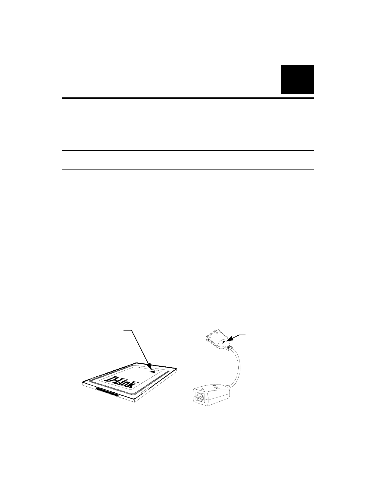
Open the shipping carton and carefully remov e all items. In add ition
to this User's Guide, ascertain that you have:
•
One DFE-660TX 10/100 Ethernet PC Card
•
One plastic storage bag for the DFE-660TX
•
One media coupler
•
One D-Link DFE-660TX Software Diskette
DFE-660TX
10/100 Et hernet PC C ard
Yellow arrow
on top side of
PC Card points
to front end plu
g
Media Coupler
Triangle
cast into
plastic
marks top
side of plug
Page 16
DFE-660TX Fast Et hernet PC Card User's Guide
8
Hardware Installation
In the event that any item is missing, or if you find any mismatch or
damage, promptly contact your dealer for correction.
Hardware Installation
Follow these four steps to install the DFE-660TX:
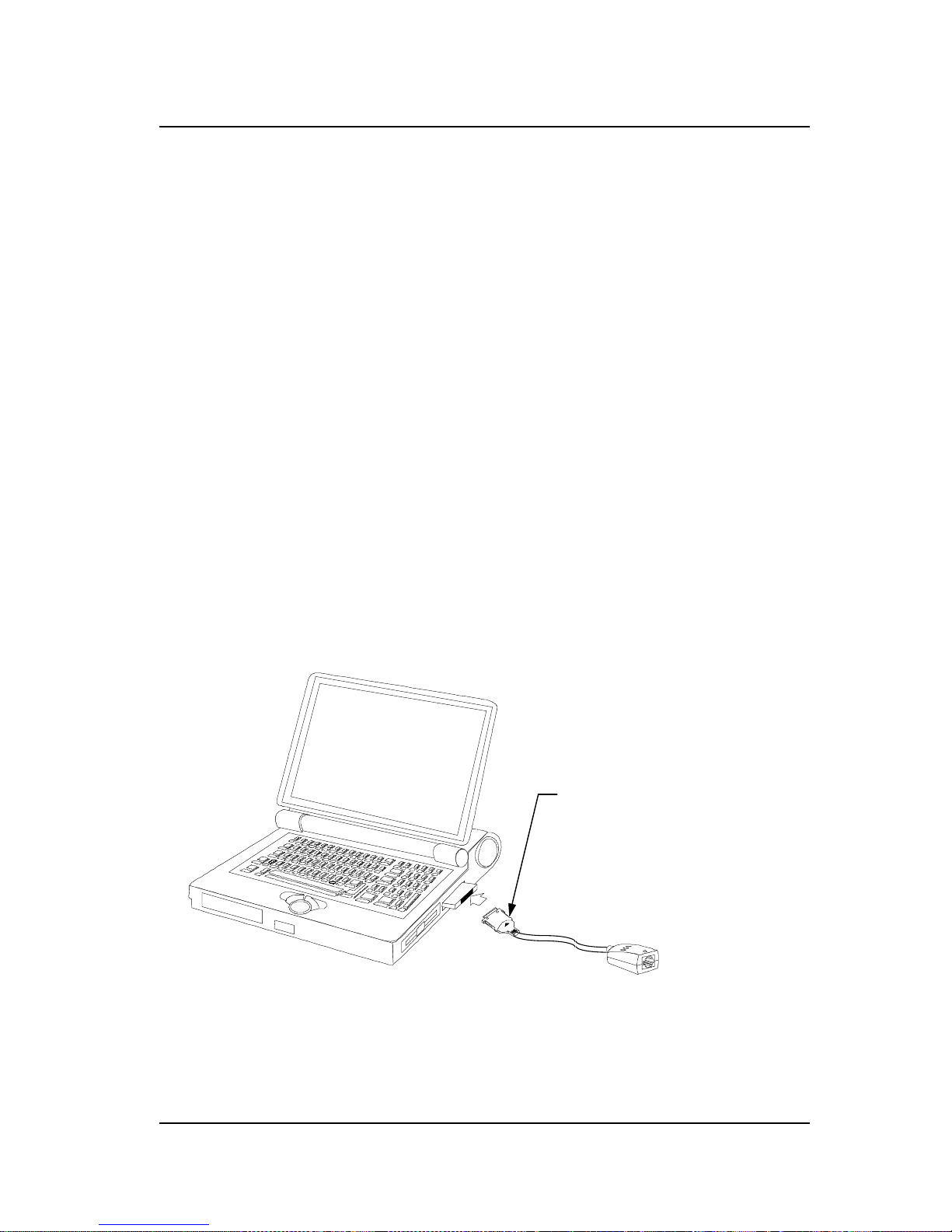
Step 1 Insert the DFE-660TX
Under the PC Card standard and the corresponding Japanese JEIDA
standard, PC Cards may safely be "hot swapped" –– it is not
necessary to switch the computer's power off before installing or
removing the DFE-660TX, or any other PC Card.
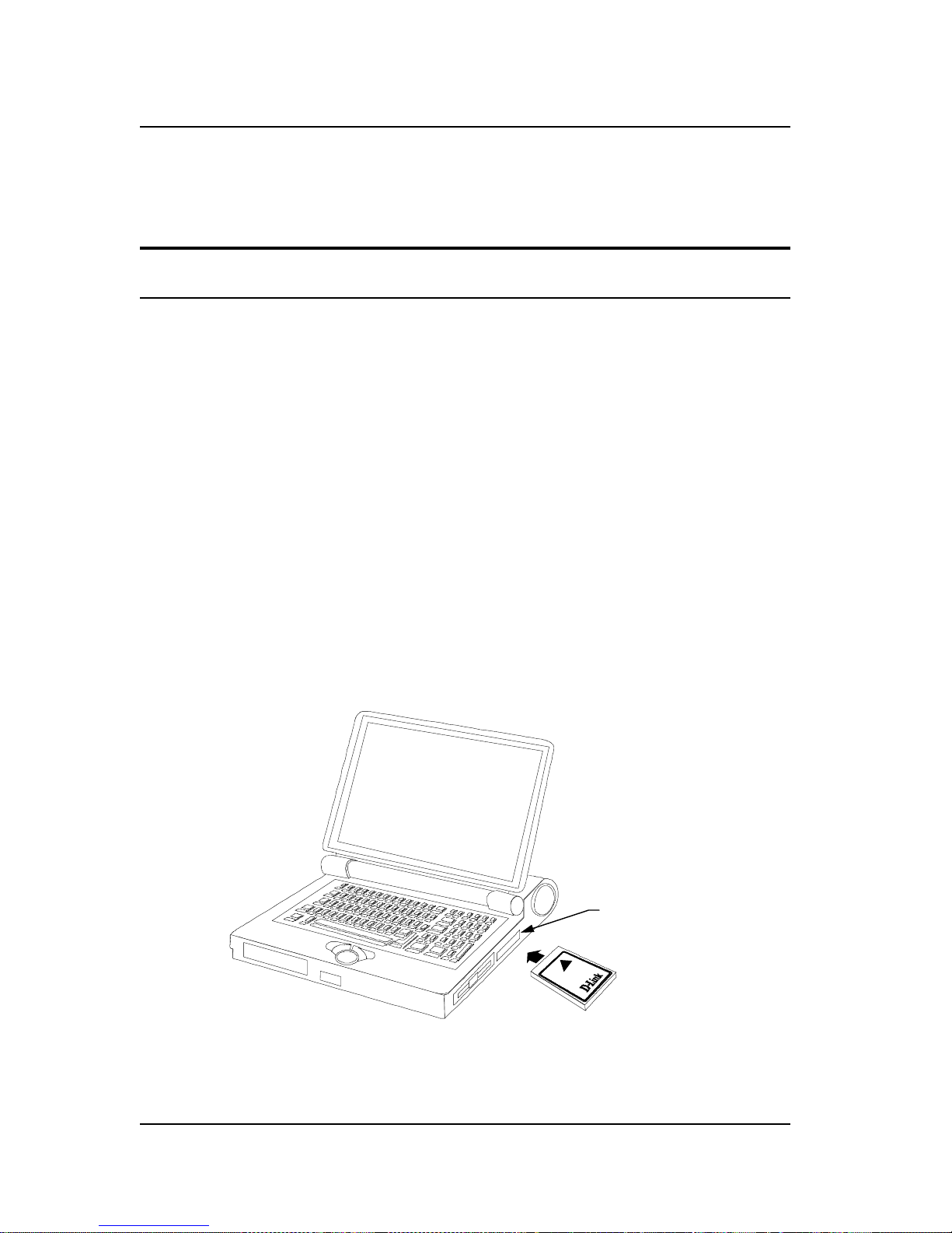
Find/select an open Type II or Type III PC Card slot on your
notebook computer's side or rear panel. Hold the DFE-660TX with
the colorful D-Link splash label u pward . Notice th at the splash label
features a yellow triangle or "arrow," which points to the front end
of the PC Card. Insert the front end of the PC Card into the CardBus
slot, and slide the PC Card all the way into the slot until it reaches a
firm stop.
Type II or Type III
PC Card slot
(s)
D-Link co l or-spla s h
label facing up
NOTE:
Many notebook PCs feature a stacked pair of PC Card slots,
logically (but not physically) designated as Slot 1 and Slot 2.
Page 17
DFE-660TX Fast Et hernet PC Card User's Guide
Hardware Installation
9
It is most usual for the lower one of the two slots in the stack
to be designated Slot 1, but there are exceptions. In the
subsequent procedure for DFE-660TX software installation,
it might be useful for you to know whether your DFE-660TX
is installed in Slot 1 or Slot 2. Under Windows 95, you can
check by opening the Control Panel / PC Card display.
Under DOS it is also possible to make a software check, but
it is more difficult. If it develops that you need to make a
trial-and-error determination or correction, then it is easy to
do: just reinstall the DFE-660TX in another slot.
Step 2 Attach the Media Coupler
The back-end receptacle of the DFE-660TX remains accessible
(approximately flush with the case of the computer) when the
DFE-660TX is properly seated in its PC Card slot. Taking care to
keep the top side of the media coupler plug up, insert the plug into
the DFE-660TX's receptacle until it is firmly seated and latched.
(The top side of the plug is labeled with a triangle molded into the
plastic.)
Keep the triangle mark on
top when you plug the media
coupler into the DFE-660TX
NOTE:
When the media coupler plug is firmly seated, it is held in
place by small latching hooks at either side of the plug. To
avoid damage when detaching the plug from the
DFE-660TX, it is necessary to depress the latch wings of
Page 18
DFE-660TX Fast Et hernet PC Card User's Guide
10
Hardware Installation
the plug. See the following section, " Remove the
DFE-660TX."
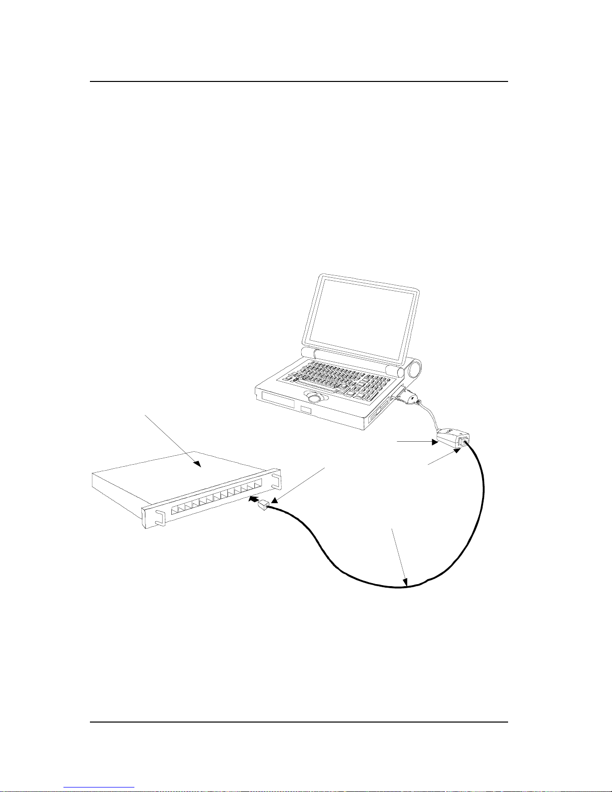
Step 3 Connect to the Network Medium
Make the network connection by running a UTP cable from the
supporting switch or hub to your media coupler. Simply plug one
end (RJ-45 plug) of the cable into an available port of the switch or
hub, and plug the other end (RJ-45 plug) into the RJ-45 socket of
your media coupler.
UTP cab le connect ing med ia c o up ler t o t he sup p orting hub
Ethernet / Fast
Ethernet Hub
Media Coupler
RJ-45 Connector s
UTP Cable
Step 4 Confirm Connection (Ln/Act Indicator)
When the notebook computer's power is ON, the DFE-660TX is
firmly seated in the slot connector, the media adapter plug is firmly
Page 19

DFE-660TX Fast Et hernet PC Card User's Guide
Hardware Installation
11
engaged (and latched) in the back-end receptacle of the DFE-660TX,
the media adapter has a good cable connection to the supporting hub,
and the supporting hub is power on and functioning properly, then
the media coupler’s Ln/Act LED glows steady green ("Linkage"
state).
If the Ln/Act LED remains dark without apparent cause, then the
most likely fault is poor engagement of the 68-pin front-end plug.
Review the following section titled "Remove the DFE-660TX," then
remove the DFE-660TX from its slot. Repeat the procedures of the
above Step 1, "Insert the DFE-660TX," taking care to ensure that the
DFE-660TX is right side up and front-end first, and that it seats
firmly in a suitable PC Card slot of your notebook. Repeat the
procedures of Steps 2 and 3 as necessary get the Ln/Act LED
confirmation.
NOTE:
You might need to wait a few seconds following notebook
powerup, or following insertion of a PC Card, for the
software processing to be completed. The Ln/Act indicator
will remain dark until the software processing is completed.
Remove the DFE-660TX
Follow these two steps to remove the DFE-660TX from its slot:
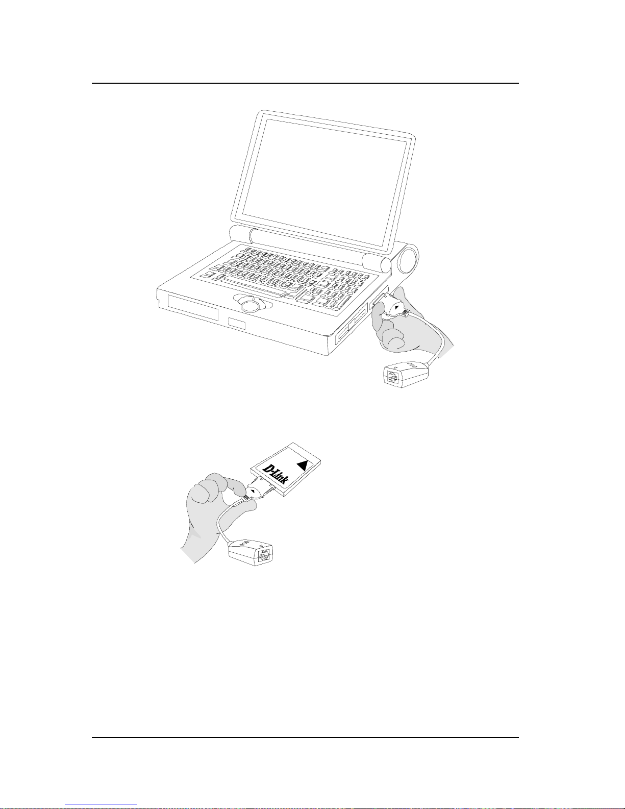
Step 1 Disconnect the Media Coupler Plug from the DFE-660TX
Unplug the media coupler from the DFE-660TX be fore ejecting the
DFE-660TX fr o m t h e P C C a rd sl o t. T he m ed ia coupler plug is held
in place by small latching hooks at either side of the plug. To
remove the media coupler plug from the DFE-660TX, i t i s n ecessary
to unlatch the hooks by depressing the two small latch wings of the
plug. Use thumb and forefinger to squeeze the latch wings into the
plug body and gently pull the plug out of its receptacle.
Page 20
DFE-660TX Fast Et hernet PC Card User's Guide
12
Hardware Installation
Dep ress cl ip wing s wh ile unp lug g in g the connecto r
Don't pull the connector without depressing the clip wings
WARNING:
Pulling the coupler plug out of its receptacle without
depressing the clip wings will cause damage to the plug.
Step 2 Eject the
DFE-660TX
from the Computer
Firmly press the computer's PC Card Eject button to disengage the
DFE-660TX from the slot connector. The DFE-660TX will then
Page 21

DFE-660TX Fast Et hernet PC Card User's Guide
Hardware Installation
13
protrude from the PC Card slot. Grip its protruding end between
your fingers and withdraw it from the PC Card slot.
Connect the Networ k Cabl e
Category 5 UTP cable is good enough to qualify under both the Fast
Ethernet cabling rules and the traditional Ethernet cabling rules. The
maximum individual cable run between any station and its
supporting hub or switch is 100m. The maximum individual cable
run joining two hubs is 10m in general, but is 100m when both hubs
qualify as Ethernet Class 2 Repeaters (
all
D-Link Ethernet hubs do
qualify). But these cable runs may need to be shorter than the given
individual maximum lengths, because their lengths are also restricted
by the rule that the maximum
aggregated
cable run between any two
stations is 205m.
Connecting for Fast Ethernet
Category 5 UTP cable is required for Fast Ethernet operation. The
maximum length of cable between the DFE-660TX and the
supporting hub is 300 ft. The cable must be “straight” (not a
“crossover” cable), with an RJ-45 plug at each end. Make the
network connection by plugging one end of the cable into the RJ-45
receptacle of the media coupler, and the other end into a port of the
supporting hub.
Connecting for 10Mbps Ethernet
Category 3, Category 4, and Category 5 UTP cable, as well as
EIA/TIA - 568 100-ohm STP cable, all qualify under traditional
Ethernet cabling rules. The maximum cable run between the
DFE-660TX and the supporting hub is 300 ft. The cable must be
“ straight” (not a “ crossover” cable) with RJ-45 plug at each end.
Page 22

DFE-660TX Fast Et hernet PC Card User's Guide
14
Hardware Installation
Make the network connection by plugging one end of the cable into
the RJ-45 receptacle of the media coupler, and the other end into a
port of the supporting hub.
Page 23

3
Software Installation
Hardware installation as described in Chapter 2 must be completed
before you proceed with software installation.
Instructions for software installation are given as README files on
the D-Link DFE-660TX Software Diskette. The diskette also holds
the Installation Director program, which helps you access the
installation instructions appropriate to your station OS and the
network environment.
Run Installation Director
For proper function of Installation Director, it is necessary that the
DFE-660TX be plugged into a PC Card slot of the notebook PC.
Ascertain that the DFE-660TX is in place, according to Step 1 of
Hardware Installation, above, then insert the D-Link DFE-660TX
Software Diskette into the diskette drive of the notebook PC. Then
select that drive as the active drive. In th e Run dialog box, or at the
command prompt, type the letter designator for that drive (here
assumed to be A), and com p lete the line as follows:
A:\install.exe
Then key
<Enter>
to run Installation Director. It will gu ide you
to, and display, the ap propriate installation instructio ns. Installation
Director provides installation instructions for every combination of
platform OS and network environment in which the DFE-660TX can
be used.
Page 24

DFE-660TX Fast Et hernet PC Card User's Guide
16
Software Installation
During your Installation Director run, if you choose DOS as your
station OS, then in some cases Installation Director will provide
additional services. In such cases, you will be prompted to select a
target directory for storage of software modules that Installation
Director will copy over from the D-Link DFE-660TX Software
Diskette. The README text will provide full information on the
additional services provided..
Installation Director also provides access to the Diagnostic Program,
which may be used to check the hardware components of the
DFE-660TX, as well as its proper interoperation with your network.
Installing 16-bit NetWare Client for DOS
If your notebook PC is running MS-DOS or an equivalent OS, then
you will need to install the traditional 16-bit NetWare Client for
DOS
.
Installation Director includes a Quick Install option for the
DFE-660TX support software required for interoperation with the
16-bit NetWare Client for DOS. The screen text, status line guide
text, and helptext of Installation Director will assist you through the
Quick Install procedure.
Page 25
A
Troubleshooting
Troubleshooting the
Hardware
Installation
If you experience any problems with the hardware installation, first
ascertain that all network cable connections are firm, that the proper
grade of cable is used for the network connection, and that the cable
makeup is correct (straight –– without un-needed crossovers in the
connector wiring). Check that the supporting hub is power-on and
operating normally, and that the hub is properly qualified (under
10Base-T and/or 100Base-TX standards).
Troubleshooting the Software Installation
You Get the
"DFE -660TX P C C ard No t Detected"
Error
You are running Installation Director, and in the Main Menu you
have selected
Quick Install 16-bit Driver for Dos Netware Client
The Quick Install run is then interrupted by an error message which
says that the
DFE-660TX
PC Card is not detected by the system.
You have followed the instruction given by the error message, to
repeat Step 1 of the Hardware Installation procedure given at the
beginning of Chapter 2 of the User's Guide. And you have then rerun Installation Director. And the same error message has come up.
Page 26

DFE-660TX Fast Et hernet PC Card User's Guide
18
Troubleshooting
Proceed as follows:
1. Exit Installation Director. Examine the CONFIG.SYS file in
the root directory of your notebook PC's startup drive (hard
drive). Ascertain that CONFIG.SYS contains a DEVICE
statement for Extended Memory Manager (EMM). Such a
statement should resemble the following example,
DEVICE = C:\DOS\EMM386.EXE X=D000-D7FF
2. If there is no similar DEVICE statement in your notebook PC's
CONFIG.SYS file, then edit the CONFIG.SYS file, adding a
statement copied exactly from the above example.
3. If there such a statement in CONFIG.SYS but the "DFE-660TX
PC Card not detected" error appears on each attempted Quick
Install run anyway, then edit that statement to read exactly the
same as the above example.
4. If, after you have completed the above instructions, the
"DFE-660TX PC Card not detected" error still appears on each
subsequent restart of the notebook PC, then please contact your
dealer or your nearest D-Link office, as listed at the end of this
User's Guide.
You need to "unload the conflicting network driver"
You are running Installation Director, and in the Main Menu you
have selected
Quick Install 16-bit Driver for Dos Netware Client.
Then you have seen the warning message which advises that the
presence in memory of another network card driver could cause a
system halt. (That warning messages appears in every Quick Install
run –– it does not indicate that there is another network card driver
already loaded into memory.) Then you have elected to continue the
Quick Install run. And the Quick Install run has indeed produced a
halt (system hangup).
Page 27

DFE-660TX Fast Et hernet PC Card User's Guide
Troubleshooting
19
If you have not been through all of those steps, then you should not
be reading this. You should be in Chapter 3, Software Installation.
And you should be staying on track with your Quick Install run.
Continue reading here
only if
your Quick Install run is actually
obstructed by a system halt (so that you can only restore your control
of the notebook PC by a restart). And
only if
after your restart
(which provides assurance of a "clean" DOS environment) you have
tried Quick Install once more (and experienced the system halt once
more). Only then should you conclude that you must "unload the
conflicting network driver."
Stay Cool and Get Help
The first thing you need to know is that "unload the conflicting
network driver" is easier said than done. If you have easy access to a
network administrator (or other resident expert), now might be a
good time to go for help. If you do not have ready access to an
expert, then help may be available from the dealer who has supplied
your DFE-660TX, and you can also get help by calling D-Link
Technical Support at the D-Link office nearest to you (see the list of
office locations at the end of this User's Guide).
"Unload" Really Means "Avoid Loading at Startup"
It is true that driver programs and related software modules, such as
those supplied on your D-Link DFE-660TX Software Diskette, are
often written so that the addition of a "/u" switch or "-u" option to
the command line for load ing the driver will cause unloading of the
same driver (if it is in fact already loaded). But such unloading is
only possible under special circumstances. So, as a practical matter,
what we really must do is
avoid loading of the conflicting driver
upon startup of the notebook PC.
A software installation procedure (such as "Quick Install 16-bit
Driver for DOS NetWare Client") copies the necessary drivers and
related modules from the supplied DFE-660TX Software Diskette,
into the target directory of the notebook PC's hard drive or other
Page 28
DFE-660TX Fast Et hernet PC Card User's Guide
20
DFE-660TX Specific ations
storage. The installation program also adds commands to the
computer's AUTOEXEC.BAT file, so that each time the computer is
subsequently booted up (and you then make certain choices in the
startup menus, if any), the drivers and related modules are
automatically loaded into m emory.
The "conflicting driver" problem now at hand arises because certain
commands already present in your notebook PC's AUTOEXEC.BAT
file are being executed during bootup, and are causing some kind of
previously installed network driver module to be loaded into
memory. The presence of that network driver in memory is now
making it impossible to load the DFE-660TX network driver
software (16-bit driver for DOS NetWare client).
So the fix is to delete from AUTOEXEC.BAT the line which is
causing the conflicting driver to be loaded. Thus we will
avoid
loading of the conflicting driver
when we next restart the notebook
PC. And the trick is to delete that line from AUTOEXEC.BAT
without deleting or changing anything which needs to remain
unchanged in AUTOEXEC.BAT (so that your notebook PC will
behave as you expect it to after each startup).
B
DFE-660TX
Specifications
Network Type:
•
Ethernet 100Base-TX
Ethernet IEEE 802.3u standard for 100Mbps baseband
CSMA/CD local area network
Page 29

DFE-660TX Fast Et hernet PC Card User's Guide
DFE-660TX Specifications
21
•
Ethernet 10BASE-T
Ethernet IEEE 802.3 standard for 10Mbps baseband CSMA/CD
local area network
Jumperless Hardware
Autonegotiation functionality
Media interface: RJ-45
LAN Chip Set:
•
Interface controller, DC-21143
•
Transceiver interface, LXT-970LC
EMI Certifications:
FCC Class B
VCCI Class B
CISPR B
Canada ICES-003, Class B
CE Certification
Host interface: CardBus
I/O base address assigned by Plug and Play system
Interrupt Number Assigned by Plug and Play system
Physical Dimensions: 85.6 × 54.0 × 5.0 mm
Environment:
Storage:
−20°
to 80°C, (4° to 176° F)
Operating: 0° to 55° C, (32° to 131° F)
Humidity: 10% to 90% non-condensing
Power Consumption: 2.0W
PCB Construction: 2 layers
Device Drivers*
•
NDIS 2.0 for Banyan
•
NDIS 2.0 for IBM Lan
Support/Services
Page 30

DFE-660TX Fast Et hernet PC Card User's Guide
22
DFE-660TX Specific ations
•
NDIS 2.0 for IBM Wrap Server,
Lan Server, and Communication
Manager 1.x
•
NDIS 2.0 for MicroSoft Lan
Manager for DOS
•
NDIS 2.0 for MicroSoft Network
Client 3.0 for DOS
•
NDIS 2. 0 for WIN/TCP
PathWay Access
•
NetWare Lite
•
NetWare DOS ODI
•
Windows 95
•
Personal NetWare
•
Windows NT 3.51
•
Windows 95 OSR2
•
Packet Driver for NCSA
•
Windows NT 4.0
•
Packet Driver for IPX
•
Packet Driver for Winsock
•
Packet Driver for FTP PC/TCP
•
*Check
http://www.dlink.com
for newest
releases of drivers.
Page 31
Offices
U.S.A. D-LINK SYSTEMS, INC.
5 Musick Irvine, CA 92618 USA
TEL: 1-714-455-1688 FAX: 1-714-455-2521
CANADA D-LINK CANADA, INC.
2180 Dunwin Drive, Unit # 6,
Mississauga Ontario, L5L 5M8, Canada
TEL: 1-905-828-0260 FAX: 1-905-828-5669
U.K. D-LINK (EUROPE) LTD.
D-Link House, 6 Garland Road, Stanmore, London HA7 1DP U. K.
TEL: 44-181-235-5555 FAX: 44-181-235-5500
GERMANY D-LINK (DEUTSCHLAND) GMBH I.G.
Bachstrae 22, 65830 Kriftel Germany
TEL: 49-6192-97110 FAX: 49-6192-971111
FRANCE D-LINK FRANCE
Le FLORILEGE #2, Allee de la Fresnerie
78330 Fontenay Le Fleury France
TEL: 33-1-3023-8688 FAX: 33-1-3023-8689
SWEDEN D-LINK A/B
World Trade Center P. O. Box 70396, 107 24 Stockholm Sweden
TEL: 46-8-700--6211 FAX: 46-8-219-640
DENMARK D-LINK DENMARK
Naverland 2 DK-2600 Glostrup Copenhagen, Denmark
TEL:45-43-969-040 FAX:45-43-424-347
SINGAPORE D-LINK SINGAPORE PTE.LTD.
77 Science Park Drive #03-03 CINTECH III,
Singapore Science Park Singapore 118256
EL : 65-774-6233 FAX: 65-774-6322
AUSTRALIA D-LINK AUSTRALIA PTY.LTD.
Unit 16, 390 Eastern Valley Way Roseville, NSW 2069 Australia
TEL: 61-2-9417-7100 FAX: 61-2-9417-1077
CHINA D-LINK BEIJING
15th Floor, Science & Technology Tower
No. 11, Baishiqiao Road, Haidian District, Beijing 100081 China
TEL: 86-10-68467106-9 FAX: 86-10-68467110
JAPAN D-LINK TOKYO
10F, 8-8-15 Nishigotanda, Shinagawa-ku, Tokyo, 141 Japan
TEL: 81-3-5434-9678 FAX: 81-3-5434-9868
INDIA D-LINK (INDIA) PVT. LTD.
Bombay Office : Plot No.5, Kur l a- Bandr a Compl ex Rd.
Off Cst Rd., Santacruz (E) Bombay - 400 098 India
TEL: 91-22-6172478 FAX: 91-22-6172476
TAIWAN D-LINK TAIWAN
Page 32

DFE-660 Series Fast Ethernet PC Card User's Guide
24
DFE-660TX Specifications
2F, No.233-2 Pao-Chiao Rd, Hsin-Tien, Taipei,Taiwan, R.O. C.
TEL: 886-2-916-1600 FAX: 886-2-914-6299
 Loading...