

Page 1

Document Created by Nick Schuster
Page 2

Table of Contents
Table of Contents
Product Overview .............................................................. 4
Introduction ................................................................................... 4
Features ............................................................................................5
Package Contents .........................................................................6
System Requirements ................................................................. 6
Hardware Overview ...........................................................7
LEDs ................................................................................................... 7
Connections ................................................................................... 7
Basic Installation ............................................................... 8
Hardware Setup ............................................................................8
Congure the access point ................................................8
Web User Interface ............................................................ 9
Wireless ..........................................................................................10
Access Point Mode .............................................................10
WDS with AP Mode ............................................................12
WDS Mode ............................................................................14
Wireless Client Mode .........................................................16
Wireless Security .................................................................17
Wired Equivalent Privacy (WEP) ..............................17
Wi-Fi Protected Access (WPA / WPA2)....................18
LAN ..........................................................................................20
IPv6 ..........................................................................................21
Advanced Settings .....................................................................22
Performance .........................................................................23
Wireless Resource Control .......................................................25
Multi-SSID ..............................................................................27
VLAN ........................................................................................29
VLAN List ..........................................................................29
Port List .............................................................................30
Add/Edit VLAN ...............................................................31
PVID Settings ..................................................................32
Intrusion .................................................................................33
Schedule ................................................................................34
Internal RADIUS Server ..................................................... 35
ARP Spoong Prevention ................................................36
Bandwidth Optimization .................................................37
AP Array ..................................................................................39
AP Array Scan .................................................................39
Conguration Settings ................................................40
Auto-RF .............................................................................44
Load Balance ..................................................................45
Captive Portal .......................................................................46
Authentication Settings-Web Redirection Only 46
Authentication Settings- Username/Password ..48
Authentication Settings- Passcode ........................50
Authentication Settings- Remote RADIUS ...........52
Authentication Settings- LDAP ................................54
Authentication Settings- POP3 ................................56
Login Page Upload .......................................................58
IP Filter Settings .............................................................59
MAC Bypass .....................................................................60
2D-Link DAP-2682 User Manual
Page 3

Table of Contents
DHCP Server .........................................................................61
Dynamic Pool Settings ................................................61
Static Pool Setting ........................................................62
Current IP Mapping List ..............................................63
Filters .......................................................................................64
Wireless MAC ACL .........................................................64
WLAN Partition ..............................................................65
Trac Control...............................................................................66
Uplink/Downlink Setting .................................................66
QoS...........................................................................................67
Trac Manager ....................................................................68
Status ..............................................................................................69
Device Information ............................................................70
Client Information ..............................................................71
WDS Information Page .....................................................72
Channel Analyze .................................................................73
Stats Page ......................................................................................74
Ethernet Trac Statistics .................................................. 74
WLAN Trac Statistics ....................................................... 75
Log ...................................................................................................76
View Log .................................................................................76
Ping Control Setting ..........................................................81
LED Settings..........................................................................81
Central WiFiManager Settings ........................................ 81
Firmware and SSL Upload ................................................82
Conguration File Upload ...............................................83
Time and Date Settings ....................................................84
Conguration and System.......................................................85
System Settings ...........................................................................86
Help .................................................................................................87
Knowledge Base ..............................................................88
Wireless Basics .............................................................................88
Wireless Installation Considerations ....................................89
Troubleshooting .............................................................. 90
Why can’t I access the web-based conguration
utility? .....................................................................................90
What can I do if I forgot my password? .......................90
How to check your IP address? ......................................91
How to statically assign an IP address? .......................92
Technical Specications ..................................................93
Log Settings ..........................................................................77
Maintenance Section ................................................................78
Administration .............................................................................79
Limit Administrator ............................................................79
System Name Settings ......................................................80
Login Settings ......................................................................80
Console Settings .................................................................80
SNMP Settings .....................................................................81
Warranty .......................................................................... 94
Central WiFiManager ..................................................... 100
Registration ...................................................................102
3D-Link DAP-2682 User Manual
Page 4

Section 1 - Product Overview
Product Overview
Introduction
D-Link, an industry pioneer in wireless networking, introduces a solution for businesses seeking to deploy next generation 802.11ac LANs. D-Link unveils
its new DAP-2682, designed specically for business-class environments such as large or enterprise corporations to provide secure and manageable dual
band wireless LAN options for network administrators.
Versatile Access Point
The DAP-2682 Access Point allows network administrators to deploy a highly manageable and extremely robust dual band wireless network. For
advanced installations, this new high-speed Access Point has integrated 802.3at Power over Ethernet (PoE) support, allowing installation of this device
in areas where power outlets are not readily available. In addition to bridging 802.11ac and 802.11b/g/n wireless networks, the DAP-2682 can bridge
to wired networks with its integrated Gigabit (10/100/1000Mbps) Ethernet port.
Enhanced Performance
The DAP-2682 delivers reliable wireless performance with maximum wireless signal rates of up to 1750Mbps. This, coupled with support for Wi-Fi Multimedia™
(WMM) Quality of Service features, makes it an ideal access point for audio, video, and voice applications. Additionally, the DAP-2682 supports load balance
features to ensure maximum performance.
Security
To help maintain a secure wireless network, the DAP-2682 provides the latest in wireless security technologies by supporting both Personal and Enterprise
versions of WPA and WPA2 (802.11i) with support for RADIUS server back end. To further protect your wireless network, MAC Address Filtering, Wireless
LAN segmentation, Disable SSID Broadcast, Rogue AP Detection, and Wireless Broadcast Scheduling are also included.
The DAP-2682 includes support for up to 16 VLANs for implementing multiple SSIDs to further help segment users on the network. The DAP-2682 also
includes a wireless client isolation mechanism, which limits direct client-to-client communication.
Power Usage
This device is an Energy Related Product (ErP) with High Network Availability (HiNA), and automatically switches to a power-saving Network Standby
mode within 1 minute of no packets being transmitted. It can also be turned o through a power switch to save energy when it is not needed.
Network Standby: 3.10 watts
* Maximum wireless signal rate derived from IEEE Standard 802.11ac, 802.11g, 802.11a, and 802.11n specications. Actual data throughput will vary. Network conditions and environmental factors, including volume of
network trac, building materials and construction, and network overhead, lower actual data throughput rate. Environmental conditions will adversely aect wireless signal range.
**Only compliant with 802.3at PoE switch and 802.3af standard can’t supply sucient power for DAP-2682
4D-Link DAP-2682 User Manual
Page 5

Section 1 - Product Overview
Features
y Provide Ethernet to Wireless LAN bridge fully IEEE 802.3/u/ab compatible on the Ethernet side and fully interoperable with IEEE 802.11ac and b/g/n/a
compliant equipment
y Compatible with IEEE 802.11b high rate standard to provide wireless 11Mbps data rate
y Compatible with IEEE 802.11g higher speed standard to provide wireless 54Mbps data rate
y Compatible with IEEE 802.11a higher speed standard to provide wireless 54Mbps data rate
y Compatible with IEEE 802.11n higher speed standard to provide wireless 450Mbps data rate
y Compatible with 802.11ac higher speed standard to provide wireless 1300Mbps data rate
y Operation at 2.4~2.5GHz and 5.15~5.85GHz frequency band to meet worldwide regulations
y Supports IEEE 802.11ac and b/g/n/a wireless data encryption with 64/128-bit WEP for security
y Allows auto fallback data rate for reliability, optimized throughput and transmission range
y Web-based conguration and management
y Supports enhanced security – WPA-PSK and WPA2-PSK, RADIUS client, and Cipher negotiation
y Supports one 802.3at PoE port
y Supports two 10/100/1000M Ethernet ports
y AP Mode, WDS Mode, WDS with AP, and Wireless Client Mode
y Supports SNMP v1,v2,v3
y Support Trap server (SNMP v1, v2c)
y Support Central WiFiManager
y Support AP Array and AP Array Setup Tool
* Maximum wireless signal rate derived from IEEE Standard 802.11ac, 802.11g, 802.11a, and 802.11n specications. Actual data throughput will vary. Network conditions and environmental factors, including volume of
network trac, building materials and construction, and network overhead, lower actual data throughput rate. Environmental conditions will adversely aect wireless signal range.
**Please note that operating frequency ranges vary depending on the regulations of individual countries and jurisdictions. The DAP-2682 isn’t supported in the 5.25~5.35GHz and 5.47 ~ 5.725GHz frequency ranges in
some regions.
***Only compliant with 802.3at PoE switch and 802.3af standard can’t supply sucient power for DAP-2682
5D-Link DAP-2682 User Manual
Page 6

Section 1 - Product Overview
Package Contents
• DAP-2682 802.11ac Power over Ethernet (PoE) Access Point
• Mounting Brackets
• Ceiling Brackets
• Ethernet Cable
• CD-ROM
• Quick Install Guide
Note: No PSU supplied. To power the units use an D-Link 802.3at PoE switch or the D-Link DPE-301GI PoE injector.
System Requirements
y Computers with Windows®, Macintosh®, or Linux-based operating systems with an installed Ethernet Adapter
y Internet Explorer 11, Safari 7, Firefox 28, or Google Chrome 33 and Above (for conguration)
6D-Link DAP-2682 User Manual
Page 7
Section 1 - Product Overview
Hardware Overview
LEDs Connections
3
2
1 Power/Status
1
Solid Red Indicates the access point has malfunctioned.
Blinking Red This LED will blink during boot-up.
Solid Green
Indicates that the DAP-2682 is working
properly.
2 Power Receptor
3 LAN (PoE) Port
Connect the supplied power adapter. Power Receptor
(*Note no longer used, replaced by PoE)
Connect to a Power over Ethernet (PoE) switch or router via
an Ethernet cable.
7D-Link DAP-2682 User Manual
Page 8
Section 2 - Installation
Basic Installation
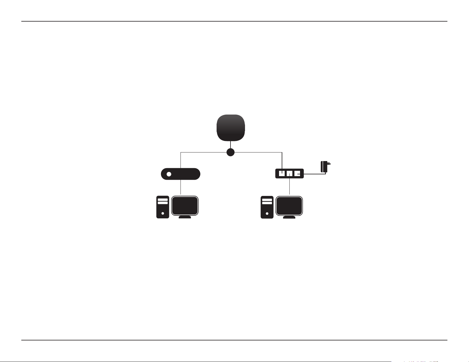
Hardware Setup
To power on the DAP-2682, you can use ONE of the following methods:
1. Plug one end of your Ethernet cable into the LAN port of the DAP-2682, and the other end into a port on a 802.3at PoE switch.
2. Purchase separately a DPE-301GI PoE injector if you need to connect the Access Point without a 802.3at PoE Switch.
Congure the access point
DAP-2682
OR
802.3at PoE Switch
Computer
PoE Injector
Computer
Power
Adapter
To set up and manage the DAP-2682, use one of the following methods:
1. Connect the access point and your computer to the same switch. Manage the access point from the computer.
Enter 192.168.0.50 in the address eld of your browser, which is the default IP address of the access point.
Log in to the Administration Web pages. The default login information is:
Username: admin
Password: (Leave the password eld blank)
2. Connect the access point and your computer via DPE-301GI. Manage the access point from the computer.
Ensure your computer is congured with a static IP address in 192.168.0.0/24 subnet.
Launch a web browser, type the default IP address of the access point (http://192.168.0.50) and then press Enter.
Log in to the Administration Web pages. The default login information is:
Username: admin
Password: (Leave the password eld blank)
8D-Link DAP-2682 User Manual
Page 9

Section 3 - Conguration
Web User Interface
The DAP-2682 supports an elaborate web user interface where the user can congure and monitor the device. Launch a web browser, type the IP
address of the access point (Default setting is http://192.168.0.50 or https://192.168.0.50) and then press Enter to login. Most of the congurable
settings are located in the left menu of the web GUI which contains section called Basic Settings, Advanced Settings and Status.
9D-Link DAP-2682 User Manual
Page 10

Section 3 - Conguration
Wireless
On the wireless settings page, you can setup the basic wireless conguration for the access point. The user can choose from 4 dierent wireless
modes:
Access Point - Used to create a wireless LAN
WDS with AP - Used to connect multiple wireless networks while still functioning as a wireless access point
WDS - Used to connect multiple wireless networks
Wireless Client - Used when the access point needs to act as a wireless network adapter for an Ethernet enabled device
Access Point Mode
Wireless Band:
Mode:
Network Name (SSID):
SSID Visibility:
Auto Channel Selection:
Select either 2.4 GHz or 5 GHz from the drop-down
menu.
Select Access Point from the drop-down menu.
Service Set Identier (SSID) is the name designated
for a specic wireless local area network (WLAN).
The SSID’s factory default setting is dlink. The SSID
can be easily changed to connect to an existing
wireless network or to establish a new wireless
network. The SSID can be up to 32 characters and
is case-sensitive.
Select Enable to broadcast the SSID across the
network, thus making it visible to all network users.
Select Disable to hide the SSID from the network.
This feature when enabled automatically selects
the channel that provides the best wireless
performance. The channel selection process only
occurs when the AP is booting up. To manually
select a channel, set this option to Disable and
select a channel from the drop-down menu.
10D-Link DAP-2682 User Manual
Page 11

Section 3 - Conguration
Channel:
Channel Width:
Authentication:
To change the channel, rst toggle the Auto Channel Selection setting to Disable, and then use the drop-down menu to make
the desired selection.
Note: The wireless adapters will automatically scan and match the wireless settings.
Allows you to select the channel width you would like to operate in. Select 20 MHz if you are not using any 802.11n wireless
clients. Auto 20/40 MHz allows you to connect to both 802.11n and 802.11b/g or 802.11a wireless devices on your network.
Use the drop-down menu to choose Open System, Shared Key, WPA-Personal, WPA-Enterprise, or 802.1x.
• Select Open System to communicate the key across the network (WEP).
• Select Shared Key to limit communication to only those devices that share the same WEP settings. If multi-SSID is
enabled, this option is not available.
• Select WPA-Personal to secure your network using a password and dynamic key changes. No RADIUS server is required.
• Select WPA-Enterprise to secure your network with the inclusion of a RADIUS server.
• Select 802.1X if your network is using port-based Network Access Control.
11D-Link DAP-2682 User Manual
Page 12

Section 3 - Conguration
WDS with AP Mode
Wireless Band:
Mode:
Network Name (SSID):
SSID Visibility:
Auto Channel Selection:
Select either 2.4GHz or 5GHz from the drop-down
menu.
WDS with AP mode is selected from the drop-down
menu.
Service Set Identier (SSID) is the name designated
for a specic wireless local area network (WLAN).
The SSID’s factory default setting is dlink. The SSID
can be easily changed to connect to an existing
wireless network or to establish a new wireless
network.
Enable or Disable SSID visibility. Enabling this
feature broadcasts the SSID across the network,
thus making it visible to all network users.
Enabling this feature automatically selects
the channel that will provide the best wireless
performance. This feature is not supported in WDS
with AP mode. The channel selection process only
occurs when the AP is booting up.
Channel:
Channel Width:
All devices on the network must share the same
channel. To change the channel, use the drop-down
menu to make the desired selection. (Note: The
wireless adapters will automatically scan and match
the wireless settings.)
Allows you to select the channel width you would
like to operate in. Select 20 MHz if you are not using
any 802.11n wireless clients. Auto 20/40 MHz allows
you to connect to both 802.11n and 802.11b/g or
802.11a wireless devices on your network.
12D-Link DAP-2682 User Manual
Page 13

Section 3 - Conguration
Remote AP MAC Address:
Site Survey:
Authentication:
Enter the MAC addresses of the APs on your network that will serve as bridges to wirelessly connect multiple networks.
Click on the Scan button to search for available wireless networks, then click on the available network that you want to
connect with.
Use the drop-down menu to choose Open System, Shared Key, or WPA-Personal.
• Select Open System to communicate the key across the network.
• Select Shared Key to limit communication to only those devices that share the same WEP settings. If multi-SSID is enabled,
this option is not available.
• Select WPA-Personal to secure your network using a password and dynamic key changes. No RADIUS server is required.
13D-Link DAP-2682 User Manual
Page 14

Section 3 - Conguration
WDS Mode
Wireless Band:
Mode:
Network Name (SSID):
SSID Visibility:
Auto Channel Selection:
Channel:
Select either 2.4GHz or 5GHz from the drop-down
menu.
WDS is selected from the drop-down menu.
Service Set Identier (SSID) is the name designated
for a specic wireless local area network (WLAN). The
SSID’s factory default setting is dlink. The SSID can
be easily changed to connect to an existing wireless
network or to establish a new wireless network.
Enable or Disable SSID visibility. Enabling this
feature broadcasts the SSID across the network, thus
making it visible to all network users.
Enabling this feature automatically selects
the channel that will provide the best wireless
performance. This feature is not supported in WDS
mode.
All devices on the network must share the same
channel. To change the channel, use the drop-down
menu to make the desired selection.
Channel Width:
Remote AP MAC Address:
Use the drop-down menu to choose 20 MHz or
Auto 20/40 MHz.
Enter the MAC addresses of the APs on your network
that will serve as bridges to wirelessly connect
multiple networks.
14D-Link DAP-2682 User Manual
Page 15

Section 3 - Conguration
Site Survey:
Authentication:
Click on the Scan button to search for available wireless networks, then click on the available network that you
want to connect with.
Use the drop-down menu to choose Open System, Shared Key, or WPA-Personal.
• Select Open System to communicate the key across the network.
• Select Shared Key to limit communication to only those devices that share the same WEP settings.
• Select WPA-Personal to secure your network using a password and dynamic key changes. No RADIUS server is
required.
15D-Link DAP-2682 User Manual
Page 16

Section 3 - Conguration
Wireless Client Mode
Wireless Band:
Mode:
Network Name (SSID):
SSID Visibility:
Auto Channel Selection:
Channel:
Select either 2.4 GHz or 5 GHz from the drop-down
menu.
Wireless Client is selected from the drop-down menu.
Service Set Identier (SSID) is the name designated
for a specic wireless local area network (WLAN). The
SSID’s factory default setting is dlink. The SSID can
be easily changed to connect to an existing wireless
network.
This option is unavailable in Wireless Client mode.
Enabling this feature automatically selects the channel
that will provide the best wireless performance. This
feature is not supported in Wireless Client mode.
The channel used will be displayed, and matches the
AP that the DAP-2682 is connected to when set to
Wireless Client mode.
Channel Width:
Site Survey:
Authentication:
Use the drop-down menu to choose 20 MHz or Auto
20/40 MHz.
Click on the Scan button to search for available
wireless networks, then click on the available network
that you want to connect with.
Will be explained in the next topic.
16D-Link DAP-2682 User Manual
Page 17

Section 3 - Conguration
Wireless Security
Wireless security is a key concern for any wireless network installed. Unlike any other networking method wireless networks will broadcast it’s presence for
anyone to connect to it. Today, wireless security has advanced to a level where it is virtually impenetrable.
There are mainly two forms of wireless encryption and they are called Wired Equivalent Privacy (WEP) and Wi-Fi Protected Access (WPA). WEP was the rst
security method developed. It is a low level encryption but better than now encryption. WPA is the newest encryption standard and with the advanced WPA2
standard wireless networks have nally reach a point where the security is strong enough to give users the peace of mind when installing wireless networks.
Wired Equivalent Privacy (WEP)
WEP provides two variations called Open System and Shared Key.
Open System will send a request to the access point and if the key used matches the one congured on the access point, the access point will return a success
message back to the wireless client. If the key does not match the one congured on the access point, the access point will deny the connection request from
the wireless client.
Shared Key will send a request to the access point and if the key used matches the one congured on the access point, the access point will send a challenge
to the client. The client will then again send a conrmation of the same key back to the access point where the access point will either return a successful or a
denial packet back to the wireless client.
Encryption:
Use the radio button to disable or enable
encryption.
Key Type*:
Key Size:
Key Index (1-4):
Select HEX or ASCII.
Select 64 Bits or 128 Bits.
Select the 1st through the 4th key to be
the active key.
Key:
Input up to four keys for encryption. You
will select one of these keys in the Key
Index drop-down menu.
**Hexadecimal (HEX) digits consist of the numbers 0-9 and the letters A-F.
*ASCII (American Standard Code for Information Interchange) is a code that represents English letters using
numbers ranging from 0-127.
17D-Link DAP-2682 User Manual
Page 18

Section 3 - Conguration
Wi-Fi Protected Access (WPA / WPA2)
WPA was created by the Wi-Fi Alliance to address the limitations and weaknesses found in WEP. This protocol is mainly based on the 802.11i
standard. There are also two variations found in WPA called WPA-Personal (PSK) and WPA-Enterprise (EAP).
WPA-EAP requires the user to install a Radius Server on the network for authentication.
WPA-Personal does not require the user to install a Radius Server on the network.
Comparing WPA-PSK with WPA-EAP, WPA-PSK is seen as a weaker authentication but comparing WPA-PSK to WEP, WPA-PSK is far more secure
than WEP. WPA-EAP is the highest level of wireless security a user can use for wireless today.
WPA2 is an upgrade of WPA. WPA2 yet again solves some possible security issues found in WPA. WPA2 has two variations called WPA2-Personal
(PSK) and WPA2-Enterprise (EAP) which is the same as found with WPA.
WPA Mode:
Cipher Type:
Group Key Update:
Pass Phrase:
When WPA-Personal is selected for Authentication
type, you must also select a WPA mode from the
drop-down menu: AUTO (WPA or WPA2), WPA2 Only,
or WPA Only. WPA and WPA2 use dierent algorithms.
AUTO (WPA or WPA2) allows you to use both WPA
and WPA2.
When you select WPA-Personal, you must also select
AUTO, AES, or TKIP from the pull down menu.
Select the interval during which the group key will
be valid. The default value of 1800 is recommended.
When you select WPA-Personal, please enter a Pass
Phrase in the corresponding eld.
18D-Link DAP-2682 User Manual
Page 19

Section 3 - Conguration
WPA Mode:
Cipher Type:
Group Key Update Interval:
Network Access Protection:
RADIUS Server:
When WPA-Enterprise is selected, you must
also select a WPA mode from the drop-down
menu: AUTO (WPA or WPA2), WPA2 Only,
or WPA Only. WPA and WPA2 use dierent
algorithms. AUTO (WPA or WPA2) allows you
to use both WPA and WPA2.
When WPA-Enterprise is selected, you must
also select a cipher type from the drop-down
menu: Auto, AES, or TKIP.
Select the interval during which the group
key will be valid. 1800 is the recommended
value as a lower interval may reduce data
transfer rates.
Enable or disable Microsoft Network Access
Protection.
Enter the IP address of the RADIUS server.
RADIUS Port:
RADIUS Secret:
Enter the RADIUS port.
Enter the RADIUS secret.
19D-Link DAP-2682 User Manual
Page 20

Section 3 - Conguration
LAN
LAN is short for Local Area Network. This is considered your internal network. These are the IP settings of the LAN interface for the DAP-2682.
These settings may be referred to as private settings. You may change the LAN IP address if needed. The LAN IP address is private to your internal
network and cannot be seen on the Internet.
Get IP From:
IP Address:
Subnet Mask:
Default Gateway:
DNS:
Static IP (Manual) is chosen here. Choose this option if
you do not have a DHCP server in your network, or if you
wish to assign a static IP address to the DAP-2682. When
Dynamic IP (DHCP) is selected, the other elds here will
be grayed out. Please allow about 2 minutes for the DHCP
client to be functional once this selection is made.
The default IP address is 192.168.0.50. Assign a static
IP address that is within the IP address range of your
network.
Enter the subnet mask. All devices in the network must
share the same subnet mask.
Enter the IP address of the gateway/router in your
network.
Enter a DNS server IP address. This is usually the local IP
address of your gateway/router.
20D-Link DAP-2682 User Manual
Page 21

Section 3 - Conguration
IPv6
Enable IPv6:
Get IP From:
IP Address:
Prex:
Default Gateway:
Check to enable the IPv6
Auto is chosen here. Choose this option the
DAP-2682 can get IPv6 address automatically
or use Static to set IPv6 address manually.
When Auto is selected, the other elds here will be grayed
out.
Enter the LAN IPv6 address used here.
Enter the LAN subnet prex length value used here.
Enter the LAN default gateway IPv6 address used here.
21D-Link DAP-2682 User Manual
Page 22

Section 3 - Conguration
Advanced Settings
In the Advanced Settings Section the user can congure advanced settings concerning Performance, Multiple SSID, VLAN, Security, Quality of Service, AP
Array, Web Redirection, DHCP Server, Filters and Scheduling. The following pages will explain settings found in the Advanced Settings section in more detail.
22D-Link DAP-2682 User Manual
Page 23

Section 3 - Conguration
Performance
On the Performance Settings page the users can congure more advanced settings concerning the wireless signal and hosting.
Wireless Band:
Wireless:
Wireless Mode:
Data Rate*:
Beacon Interval (40-500):
Select either 2.4GHz or 5GHz.
Use the drop-down menu to turn the wireless function On or O.
The dierent combination of clients that can be supported include
Mixed 802.11n, 802.11g and 802.11b, Mixed 802.11g and 802.11b
and 802.11n Only in the 2.4 GHz band and Mixed 802.11n, 802.11a,
802.11a only, and 802.11n Only in the 5 GHz band. Please note that
when backwards compatibility is enabled for legacy (802.11a/g/b)
clients, degradation of 802.11n wireless performance is expected.
Indicate the base transfer rate of wireless adapters on the wireless
LAN. The AP will adjust the base transfer rate depending on the base
rate of the connected device. If there are obstacles or interference, the
AP will step down the rate. This option is enabled in Mixed 802.11g
and 802.11b mode (for 2.4 GHz) and 802.11a only mode (for 5 GHz).
The choices available are Best (Up to 54), 54, 48, 36, 24, 18, 12, 9, 6
for 5 GHz and Best (Up to 54), 54, 48, 36, 24, 18, 12, 9, 6, 11, 5.5, 2 or
1 for 2.4 GHz.
Beacons are packets sent by an access point to synchronize a
wireless network. Specify a value in milliseconds. The default (100)
is recommended. Setting a higher beacon interval can help to save
the power of wireless clients, while setting a lower one can help a
wireless client connect to an access point faster.
DTM Interval (1-15):
Select a Delivery Trac Indication Message setting between 1 and 15. 1 is the default setting. DTIM is a countdown informing
clients of the next window for listening to broadcast and multicast messages.
23D-Link DAP-2682 User Manual
Page 24

Section 3 - Conguration
Transmit Power:
WMM (Wi-Fi Multimedia):
Ack Time Out
(2.4 GHZ, 64~200):
Short GI:
IGMP Snooping:
Multicast Rate :
Maximum Multicast
Bandwidth :
This setting determines the power level of the wireless transmission. Transmitting power can be adjusted to eliminate overlapping
of wireless area coverage between two access points where interference is a major concern. For example, if wireless coverage is
intended for half of the area, then select 50% as the option. Use the drop-down menu to select 100%, 50%, 25%, or 12.5%.
WMM stands for Wi-Fi Multimedia. Enabling this feature will improve the user experience for audio and video applications over
a Wi-Fi network.
To eectively optimize throughput over long distance links enter a value for Acknowledgement Time Out between 25 and 200
microseconds for 5 GHz or from 64 to 200 microseconds in the 2.4 GHz in the eld provided.
Select Enable or Disable. Enabling a short guard interval can increase throughput. However, be aware that it can also increase
the error rate in some installations due to increased sensitivity to radio-frequency installations.
Select Enable or Disable. Internet Group Management Protocol allows the AP to recognize IGMP queries and reports sent between
routers and an IGMP host (wireless STA). When IGMP snooping is enabled, the AP will forward multicast packets to an IGMP host
based on IGMP messages passing through the AP.
Select the multicast rate to adjust multicast packet data rates.
Set the multicast packets maximum bandwidth pass through rate from the Ethernet interface to the Access Point.
Multicast Bandwidth
Control :
HT20/40 Coexistence :
Transfer DHCP Oer to
Unicast :
Adjust the multicast packet data rate here. The multicast rate is supported in AP mode, (2.4 GHZ and 5 GHZ) and WDS
with AP mode, including Multi-SSIDs.
Enable this option to reduce interference from other wireless networks in your area. If the channel width is operating at 40MHz
and there is another wireless network’s channel over-lapping and causing interference, the Access Point will automatically change
to 20MHz.
Enable to transfer the DHCP Oer to Unicast from LAN to WLAN, suggest to enable this function if stations number is larger than 30.
24D-Link DAP-2682 User Manual
Page 25

Section 3 - Conguration
Wireless Resource Control
The Wireless Resource Control window is used to congure the wireless connection settings so that the device can detect the better wireless
connection in your environment.
Wireless band:
Band Steering:
Band Steering Age:
Band Steering
Dierence:
Select 2.4GHz or 5GHz.
Use the drop-down menu to Enable the Band
Steering function. When the wireless clients
support both 2.4GHz and 5GHz and the 2.4GHz
signal is not strong enough, the device will use
5GHz as higher priority.
Enter the time in seconds to specify the interval
of updating information.
The Band Steering dierence value is equal to
the number of 5GHz wireless client connections
minus the number of 2.4GHz wireless client connections. If the number of 5GHz wireless client
connections minus the number of 2.4GHz wireless client connections exceed this value, the
extra 5GHz wireless client connections will be
forced to connect to the 2.4GHz band and not
the 5GHz band.
Band Steering
Refuse Num:
Connection Limit:
Enter the maximum 5GHz connection attempts allowed before the 5GHz preferred function will be disabled for the wireless station connection.
Select Enable or Disable. This is an option for load balancing. This determines whether to limit the number of users
accessing this device. The exact number is entered in the User Limit eld below. This feature allows the user to share the
wireless network trac and the client using multiple APs. If this function is enabled and when the number of users exceeds this value, or the network utilization of this AP exceeds the percentage that has been specied, the DAP-2682 will
not allow clients to associate with the AP.
25D-Link DAP-2682 User Manual
Page 26

Section 3 - Conguration
User Limit:
11n Preferred:
Network Utilization:
Aging out:
RSSI Threshold:
Data Rate Threshold:
ACL RSSI:
Set the maximum amount of users that are allowed access (zero to 64 users) to the device using the specied wireless
band. The default setting is 20.
Use the drop-down menu to Enable the 11n Preferred function. The wireless clients with 802.11n protocol will have
higher priority to connect to the device.
Set the maximum utilization of this access point for service. The DAP-2682 will not allow any new clients to associate
with the AP if the utilization exceeds the value the user species. Select a utilization percentage between 100%, 80%,
60%, 40%, 20%, or 0%. When this network utilization threshold is reached, the device will pause one minute to allow network congestion to dissipate.
Use the drop-down menu to select the criteria of disconnecting the wireless clients. Available options are RSSI and Data
Rate.
When RSSI is selected in the Aging out drop-down menu, select the percentage of RSSI here. When the RSSI of wireless
clients is lower than the specied percentage, the device disconnects the wireless clients.
When Data Rate is selected in the Aging out drop-down menu, select the threshold of data rate here. When the data
rate of wireless clients is lower than the specied number, the device disconnects the wireless clients.
Use the drop-down menu to Enable the function. When enabled, the device denies the connection request from the
wireless clients with the RSSI lower than the specied threshold below.
ACL RSSI Threshold:
Set the ACL RSSI Threshold.
26D-Link DAP-2682 User Manual
Page 27

Section 3 - Conguration
Multi-SSID
The device supports up to four multiple Service Set Identiers. You can set the Primary SSID in the Basic > Wireless section. The SSID’s factory
default setting is dlink. The SSID can be easily changed to connect to an existing wireless network or to establish a new wireless network.
Enable Multi-SSID:
Band:
Index:
SSID:
SSID Visibility:
Security:
Check to enable support for multiple SSIDs.
Select 2.4GHz or 5GHz.
You can select up to three multi-SSIDs. With the Primary
SSID, you have a total of four multi-SSIDs.
Service Set Identier (SSID) is the name designated for a
specic wireless local area network (WLAN). The SSID’s
factory default setting is dlink. The SSID can be easily
changed to connect to an existing wireless network or
to establish a new wireless network.
Enable or Disable SSID visibility. Enabling this feature
broadcasts the SSID across the network, thus making
it visible to all network users.
The Multi-SSID security can be Open System, WPAPersonal, or WPA-Enterprise. For a detailed description
of the Open System parameters please go to page
23. For a detailed description of the WPA-Personal
parameters please go to page 24. For a detailed description of the WPA-Enterprise parameters please go to page 25.
Priority:
WMM (Wi-Fi
Multimedia):
Select the priority level of the SSID selected.
WMM stands for Wi-Fi Multimedia. Enabling this feature will improve the user experience for audio and video applications over a Wi-Fi
network.
27D-Link DAP-2682 User Manual
Page 28

Section 3 - Conguration
Encryption:
Key Type:
Key Size:
Key Index (1-4):
Key:
WPA Mode:
Cipher Type:
Group Key Update Interval:
Pass Phrase:
When you select Open System, toggle between Enable and Disable. If Enable is selected, the Key Type, Key Size, Key Index
(1~4), Key, and Conrm Keys must also be congured.
Select HEX or ASCII.
Select 64-bit or 128-bit.
Select from the 1st to 4th key to be set as the active key.
Input up to four keys for encryption. You will select one of these keys in the Key Index drop-down menu.
When you select either WPA-Personal or WPA-Enterprise, you must also choose a WPA mode from the drop-down menu: AUTO
(WPA or WPA2), WPA2 Only, or WPA Only. WPA and WPA2 use dierent algorithms. AUTO (WPA or WPA2) allows you to use both
WPA and WPA2. In addition, you must congure Cipher Type, and Group Key Update Interval.
Select Auto, AES, or TKIP from the drop-down menu.
Select the interval during which the group key will be valid. The default value of 1800 seconds is recommended.
When you select WPA-Personal, please enter a Pass Phrase in the corresponding eld.
Conrm Pass Phrase:
RADIUS Server:
RADIUS Port:
RADIUS Secret:
When you select WPA-Personal, please re-enter the Pass Phrase entered in the previous item in the corresponding eld.
When you select WPA-Enterprise, enter the IP address of the RADIUS server. In addition, you must congure RADIUS Port and
RADIUS Secret.
Enter the RADIUS port.
Enter the RADIUS secret.
28D-Link DAP-2682 User Manual
Page 29

Section 3 - Conguration
VLAN
VLAN List
The DAP-2682 supports VLANs. VLANs can be created with a Name and VID. Mgmt (TCP stack), LAN, Primary/Multiple SSID, and WDS connection
can be assigned to VLANs as they are physical ports. Any packet which enters the DAP-2682 without a VLAN tag will have a VLAN tag inserted
with a PVID. The VLAN List tab displays the current VLANs.
VLAN Status:
VLAN Mode:
Use the radio button to toggle to Enable. Next,
go to the Add/Edit VLAN tab to add or modify
an item on the VLAN List tab.
The current VLAN mode is displayed.
29D-Link DAP-2682 User Manual
Page 30
Section 3 - Conguration
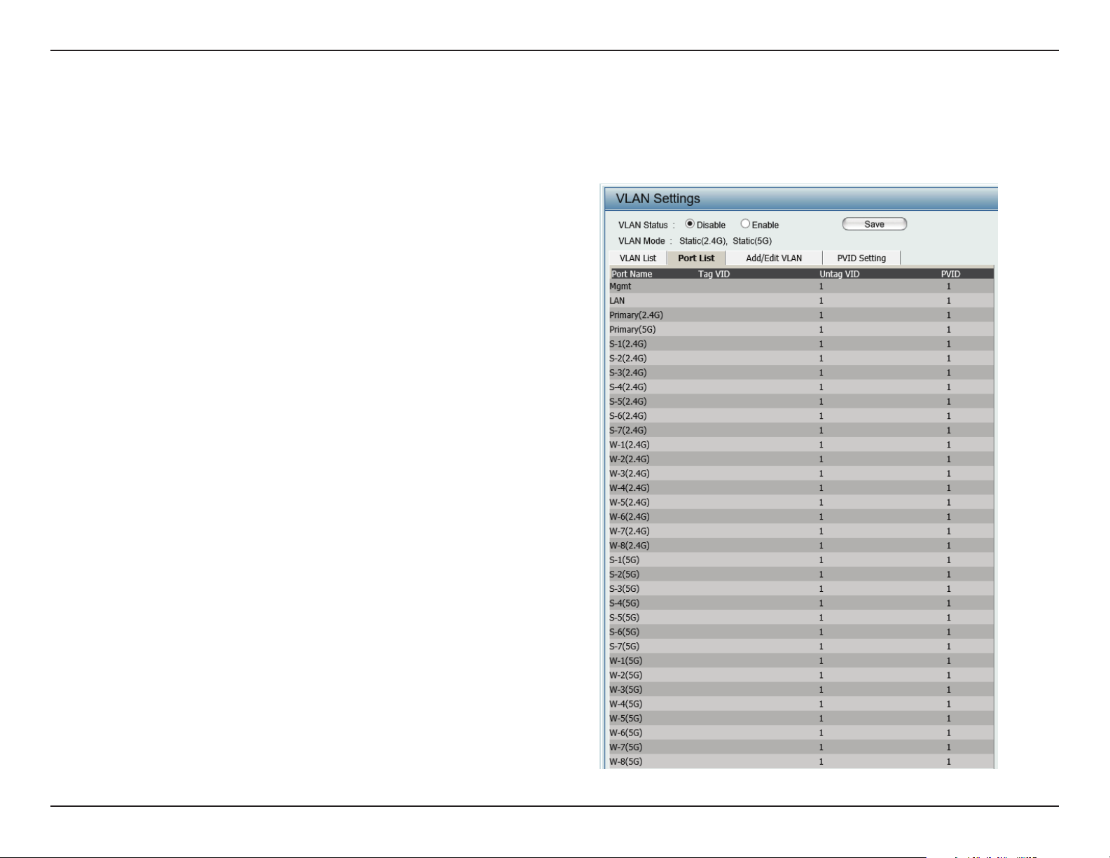
Port List
The Port List tab displays the current ports. If you want to congure the guest and internal networks on a Virtual LAN (VLAN), the switch and
DHCP server you are using must also support VLANs. As a prerequisite step, congure a port on the switch for handling VLAN tagged packets as
described in the IEEE 802.1Q standard.
VLAN Status:
Port Name:
Tag VID:
Untag VID:
PVID:
Use the radio button to toggle to Enable. Next, go to
the Add/Edit VLAN tab to add or modify an item on
the VLAN List tab.
The name of the port is displayed in this column.
The Tagged VID is displayed in this column.
The Untagged VID is displayed in this column.
The Port VLAN Identier is displayed in this column.
30D-Link DAP-2682 User Manual
Page 31

Section 3 - Conguration
Add/Edit VLAN
The Add/Edit VLAN tab is used to congure VLANs. Once you have made the desired changes, click the Save button to let your changes take
eect.
VLAN Status:
VLAN ID:
VLAN Name:
Use the radio button to toggle to Enable.
Provide a number between 1 and 4094
for the Internal VLAN.
Enter the VLAN to add or modify.
31D-Link DAP-2682 User Manual
Page 32

Section 3 - Conguration
PVID Settings
The PVID Setting tab is used to enable/disable the Port VLAN Identier Auto Assign Status as well as to congure various types of PVID settings.
Click the Save button to let your changes take eect.
VLAN Status:
PVID Auto Assign Status:
Use the radio button to toggle between
Enable and Disable.
Use the radio button to toggle PVID auto
assign status to Enable.
32D-Link DAP-2682 User Manual
Page 33

Section 3 - Conguration
Intrusion
The Wireless Intrusion Protection window is used to set APs as All, Valid, Neighborhood, Rogue, and New. Click the Save button to let your changes
take eect.
Wireless Band:
AP List:
Detect:
Select 2.4GHz or 5GHz.
The choices include All, Valid, Neighbor,
Rogue, and New.
Click this button to initiate a scan of the
network.
33D-Link DAP-2682 User Manual
Page 34

Section 3 - Conguration
Schedule
The Wireless Schedule Settings window is used to add and modify scheduling rules on the device. Click the Save button to let your changes take
eect.
Wireless Schedule:
Name:
Index:
SSID:
Day(s):
All Day(s):
Start Time:
Use the drop-down menu to enable the device’s
scheduling feature.
Enter a name for the new scheduling rule in the eld
provided.
Use the drop-down menu to select the desired SSID.
This read-only eld indicates the current SSID in use. To
create a new SSID, go to the Wireless Settings window
(Basic Settings > Wireless).
Toggle the radio button between All Week and Select
Day(s). If the second option is selected, check the
specic days you want the rule to be eective on.
Check this box to have your settings apply 24 hours
a day.
Enter the beginning hour and minute, using a 24-hour
clock.
End Time:
Enter the ending hour and minute, using a 24-hour
clock.
34D-Link DAP-2682 User Manual
Page 35

Section 3 - Conguration
Internal RADIUS Server
The DAP-2682 features a built-in RADIUS server. Once you have nished adding a RADIUS account, click the Save button to let your changes take
eect. The newly-created account will appear in this RADIUS Account List. The radio buttons allow the user to enable or disable the RADIUS account.
Click the icon in the delete column to remove the RADIUS account. We suggest you limit the number of accounts below 30.
User Name:
Password:
Status:
RADIUS Account List:
Enter a name to authenticate user access to the
internal RADIUS server.
Enter a password to authenticate user access to the
internal RADIUS server. The length of your password
should be 8~64.
Toggle the drop-down menu between Enable and
Disable.
Displays the list of users.
35D-Link DAP-2682 User Manual
Page 36

Section 3 - Conguration
ARP Spoong Prevention
The ARP Spoong Prevention feature allows users to add IP/MAC address mapping to prevent arp spoong attack.
ARP Spoong Prevention:
Gateway IP Address:
Gateway MAC Address:
This check box allows you to enable the arp
spoong prevention function.
Enter a gateway IP address.
Enter a gateway MAC address.
36D-Link DAP-2682 User Manual
Page 37

Section 3 - Conguration
Bandwidth Optimization
The Bandwidth Optimization window allows the user to manage the bandwidth of the device and arrange the bandwidth for various wireless clients.
When the Bandwidth Optimization ruile is nished, click the Add button. To discard the Add Bandwidth Optimization Rule settings, click the Clear
button. Click the Save button to let your changes take eect.
Enable Bandwidth
Optimization:
Downlink Bandwidth:
Uplink Bandwidth:
Allocate average BW
for each station:
Allocate maximum BW
for each station:
Allocate dierent BW
for a/b/g/n stations:
Allocate specic BW
for SSID:
Use the drop-down menu to Enable the Bandwidth
Optimization function.
Enter the downlink bandwidth of the device in
Mbits per second.
Enter the uplink bandwidth of the device in Mbits
per second.
AP will distribute average bandwidth for each
client.
Specify the maximum bandwidth for each
connected client. Reserve certain bandwidth for
future clients.
The weight of 11b/g/n and 11a/n client are
10%/20%/70% ; 20%/80%. AP will distribute
dierent bandwidth for 11a/b/g/n clients.
All clients share the total bandwidth.
Rule Type:
Use the drop-down menu to select the type
that is applied to the rule. Available options are:
Allocate average BW for each station, Allocate
maximum BW for each station, Allocate
dierent BW for 1a/b/g/n stations, and Allocte
specic BW for SSID.
37D-Link DAP-2682 User Manual
Page 38

Section 3 - Conguration
Band:
SSID Index:
Downlink Speed:
Uplink Speed:
Use the drop-down menu to toggle the wireless band between 2.4GHz and 5GHz.
Use the drop-down menu to select the SSID for the specied wireless band.
Enter the limitation of the downloading speed in either Kbits/sec or Mbits/sec for the rule.
Enter the limitation of the uploading speed in either Kbits/sec or Mbits/sec for the rule.
38D-Link DAP-2682 User Manual
Page 39

Section 3 - Conguration
AP Array
AP Array Scan
The AP Array window is used to create up to 32 APs on a local network to be organized into a single group in order to increase ease of management.
Click the Save button to let your changes take eect. Central WiFiManager and AP Array are mutually exclusive functions.
Enable AP Array:
AP Array Name:
AP Array Password:
Scan AP Array List:
Connection Status:
AP Array List:
Select the check box to enable the AP array
function. The three modes that are available are
Master, Backup Master, and Slave. APs in the
same array will use the same conguration. The
conguration will sync the Master AP to the Slave
AP and the Backup Master AP when a Slave AP and
a Backup Master AP join the AP array.
Enter an AP array name for the group here.
Enter an AP array password for the group here.
This password must be the same on all the APs
in the group.
Click this button to initiate a scan of all the
available APs currently on the network.
Display the AP array connection status.
This table displays the current AP array status for
the following parameters: Array Name, Master
IP, MAC, Master, Backup Master, Slave, and Total.
Current Members:
This table displays all the current array members.
The DAP-2682 AP array feature supports up to
eight AP array members.
39D-Link DAP-2682 User Manual
Page 40

Section 3 - Conguration
Conguration Settings
In the AP array conguration settings windows, users can specify which settings all the APs in the group will inherit from the master AP. Make the
required selection in this window and click the Save button to accept the changes made.
Enable AP Array
Conguration:
Wireless Basic
Settings:
Wireless Advanced
Settings:
Multiple SSID & VLAN:
Advanced Functions:
Administration
Settings:
Select to Enable or Disable the AP array congure
feature here.
Select this option to specify the basic wireless
settings that the APs in the group will inherit.
Select this option to specify the advanced wireless
settings that the APs in the group will inherit.
Select this option to specify the multiple SSIDs
and VLAN settings that the APs in the group will
inherit.
Select this option to specify the other advanced
settings that the APs in the group will inherit.
Select this option to specify the administrative
settings that the APs in the group will inherit.
40D-Link DAP-2682 User Manual
Page 41

Section 3 - Conguration
Wireless Basic Settings
Network Name (SSID):
SSID Visibility:
Auto Channel Selection:
Channel Width:
Security:
Captive Prole:
Band:
Wireless:
Wireless Mode:
Select this option to use the same SSID.
Select this option to enable SSID visibility.
Select this option to use auto channel selection.
Select this option to use the same channel width.
Select this option to use the same wireless security.
Select this option to use the same captive prole settings.
Select this option to use the same wireless band.
Wireless Advanced Settings
Select this option to use the same wireless
settings.
Select this option to use the same wireless mode.
Data Rate:
Beacon Interval:
DTIM Interval:
Transmit Power:
WMM (Wi-Fi
Multimedia):
Ack Time Out:
Wireless ACL:
Select this option to use the same data rate.
Select this option to use the same beacon interval.
Select this option to use the same DTIM interval.
Select this option to use the same transmit power.
Select this option to use the same WMM settings.
Select this option to use the same ACK timeout value.
Select this option to use the same wireless ACL settings.
41D-Link DAP-2682 User Manual
Page 42

Section 3 - Conguration
Short GI:
Link Integrity:
Connection Limit:
IGMP Snooping::
SSID:
SSID Visibility:
Security:
WMM:
Captive Prole:
Select this option to use the same short GI settings.
Select this option to use the same link integrity settings.
Select this option to use the same connection limit value.
Select this option to use the same IGMP snooping settings.
Multiple SSID & VLAN
Select this option to use the same multi-SSIDs.
Select this option to use the same SSID visible.
Select this option to use the same wireless security
settings.
Select this option to use the same WMM settings.
Select this option to use the same captive prole settings.
VLAN:
Schedule Settings:
QoS Settings:
Log Settings:
Time and Date Settings:
Select this option to use the same VLAN settings.
Advanced Functions
Select this option to use the same schedule
settings.
Select this option to use the same Quality of
Service settings.
Select this option to use the same log settings.
Select this option to use the same time and date
settings.
42D-Link DAP-2682 User Manual
Page 43

Section 3 - Conguration
ARP Spoong
Prevention:
Bandwidth
Optimization:
Captive Portal:
Auto RF:
Load Balance:
DHCP Server Settings:
System Name Settings:
SNMP Settings:
Select this option to use the same ARP spoong prevention settings.
Select this option to use the same bandwidth optimization settings.
Select this option to use the same captive portal settings.
Select this option to use the same auto-RF settings.
Select this option to use the same load balancing settings.
Select this option to use the same DHCP server settings.
Administration Settings
Select this option to use the same system name.
Select this option to use the same SNMP settings.
Login Settings:
Console Settings:
Limit Administrator:
Ping Control Setting:
Select this option to use the same login settings.
Select this option to use the same console settings.
Select this option to use the same limit administrator settings.
Select this option to use the same ping control settings.
43D-Link DAP-2682 User Manual
Page 44

Section 3 - Conguration
Auto-RF
In this windows, users can view and congure the automatic radio frequency settings as well as congure the the auto-initiate period and threshold
values. Click the Save button to accept the changes made.
Enable: Auto-RF:
Initiate Auto-RF:
Auto-Initiate:
Auto-Initiate Period:
RSSI Threshold:
RF Report Frequency:
Select to Enable or Disable the auto-RF feature
here.
Click the Auto-RF Optimize button to initiate the
auto-RF optimization feature.
Select the Enable or Disable the auto-initiate
feature here.
After enabling the auto-initiate option, the autoinitiate period value can be entered here. This
value must be between 1 and 24 hours.
Select the RSSI threshold value here. This value is
listed in the drop-down menu in increments of
10% from 10% to 100%.
Enter the RF report frequency value here.
44D-Link DAP-2682 User Manual
Page 45

Section 3 - Conguration
Load Balance
In this window, users can view and congure the AP array’s load balancing settings. Click the Save button to accept the changes made.
Enable Load Balance:
Active Threshold:
Select to Enable or Disable the load balance
feature here.
Enter the active threshold value here.
45D-Link DAP-2682 User Manual
Page 46

Section 3 - Conguration
Captive Portal
Authentication Settings-Web Redirection Only
The Captive Portal is a built-in web authentication server. When a station connects to an AP, the web browser will be redirected to a web authentication
page. In this window, user can view and congure the Captive Portal settings. After selecting Web Redirection Only as the Authentication Type, we
can congure the redirection website URL that will be applied to each wireless client in this network.
Session
timeout(1-1440) :
Band :
SSID Index :
Authentication Type :
Web Redirection State :
URL Path :
Enter the session timeout value here. This value
can be from 1 to 1440 minutes. By default, this
value is 60 minutes.
Select 2.4GHz or 5GHz.
Select the SSID for this Authentication.
Select the captive portal encryption type here.
Options to choose from are Web Redirection,
Username/Password, Passcode, Remote
RADIUS, LDAP and POP3. In this section we’ll
discuss the Web Redirection option.
Default setting is Enable when select Web
Redirection Only.
Select whether to use either HTTP or HTTPS
here. After selecting either http:// or https://,
enter the URL of the website that will be used
in the space provided.
IPIF Status :
VLAN Group :
Select to Enable or Disable the Captive Portal
with its IP interface feature here.
Enter the VLAN Group ID here.
46D-Link DAP-2682 User Manual
Page 47

Section 3 - Conguration
Get IP From :
IP Address :
Subnet Mask :
Gateway :
DNS :
Static IP (Manual) is chosen here. Choose this
option if you do not have a DHCP server in
your network, or if you wish to assign a static
IP address to the DAP-2682. When Dynamic
IP (DHCP) is selected, the other elds here will
be grayed out. Please allow about 2 minutes
for the DHCP client to be functional once this
selection is made.
Assign a static IP address that is within the IP
address range of your network.
Subnet Mask : Enter the subnet mask. All
devices in the network must share the same
subnet mask.
Enter the IP address of the gateway/router in
your network.
Enter a DNS server IP address. This is usually
the local IP address of your gateway/router.
47D-Link DAP-2682 User Manual
Page 48

Section 3 - Conguration
Authentication Settings- Username/Password
The Captive Portal is a built-in web authentication server. When a station connects to an AP, the web browser will be redirected to a web authentication
page. In this window, user can view and congure the Captive Portal settings. After selecting Username/Password as the Authentication Type, we
can congure the Username/Password authentication that will be applied to each wireless client in this network.
Session
timeout(1-1440) :
Band :
SSID Index :
Authentication Type :
Web Redirection State :
URL Path :
Enter the session timeout value here. This value
can be from 1 to 1440 minutes. By default, this
value is 60 minutes.
Select 2.4GHz or 5GHz.
Select the SSID for this Authentication.
Select the captive portal encryption type here.
Options to choose from are Web Redirection,
Username/Password, Passcode, Remote
RADIUS, LDAP and POP3. In this section we’ll
discuss the Username/Password option.
Default is Disable or select Enable to enable the
website redirection feature.
Select whether to use either HTTP or HTTPS
here. After selecting either http:// or https://,
enter the URL of the website that will be used
in the space provided.
IPIF Status :
VLAN Group :
Select to Enable or Disable the Captive Portal
with its IP interface feature here.
Enter the VLAN Group ID here.
48D-Link DAP-2682 User Manual
Page 49

Section 3 - Conguration
Get IP From :
IP Address :
Subnet Mask :
Gateway :
DNS :
Static IP (Manual) is chosen here. Choose this
option if you do not have a DHCP server in
your network, or if you wish to assign a static
IP address to the DAP-2682. When Dynamic
IP (DHCP) is selected, the other elds here
will be grayed out. Please allow about 2
minutes for the DHCP client to be functional
once this selection is made.
Assign a static IP address that is within the
IP address range of your network.
Subnet Mask : Enter the subnet mask. All
devices in the network must share the same
subnet mask.
Enter the IP address of the gateway/router
in your network.
Enter a DNS server IP address. This is usually
the local IP address of your gateway/router.
Username:
Password:
Enter the username for the new account
here.
Enter the password for the new account here.
49D-Link DAP-2682 User Manual
Page 50

Section 3 - Conguration
Authentication Settings- Passcode
The Captive Portal is a built-in web authentication server. When a station connects to an AP, the web browser will be redirected to a web authentication
page. In this window, user can view and congure the Captive Portal settings. After selecting Passcode as the Authentication Type, we can congure
the Passcode authentication that will be applied to each wireless client in this network.
Session
timeout(1-1440) :
Band :
SSID Index :
Authentication Type :
Web Redirection State :
URL Path :
IPIF Status :
Enter the session timeout value here. This value
can be from 1 to 1440 minutes. By default, this
value is 60 minutes.
Select 2.4GHz or 5GHz.
Select the SSID for this Authentication.
Select the captive portal encryption type here.
Options to choose from are Web Redirection,
Username/Password, Passcode, Remote
RADIUS, LDAP and POP3. In this section we’ll
discuss the Passcode option.
Default is Disable or select Enable to enable the
website redirection feature.
Select whether to use either HTTP or HTTPS
here. After selecting either http:// or https://,
enter the URL of the website that will be used
in the space provided.
Select to Enable or Disable the Captive Portal
with its IP interface feature here.
VLAN Group :
Enter the VLAN Group ID here.
50D-Link DAP-2682 User Manual
Page 51

Section 3 - Conguration
Get IP From :
IP Address :
Subnet Mask :
Gateway :
DNS :
Passcode Quantity:
Static IP (Manual) is chosen here. Choose this
option if you do not have a DHCP server in your
network, or if you wish to assign a static IP address
to the DAP-2682. When Dynamic IP (DHCP) is
selected, the other elds here will be grayed out.
Please allow about 2 minutes for the DHCP client
to be functional once this selection is made.
Assign a static IP address that is within the IP
address range of your network.
Subnet Mask : Enter the subnet mask. All devices
in the network must share the same subnet mask.
Enter the IP address of the gateway/router in
your network.
Enter a DNS server IP address. This is usually the
local IP address of your gateway/router.
Enter the number of ticket that will be used here.
Duration:
Last Active Day:
User Limit:
Enter the duration value, in hours, for this
passcode.
Select the last active date for this passcode here.
Year, Month and Day selections can be made.
Enter the maximum amount of users that can use
this passcode at the same time
51D-Link DAP-2682 User Manual
Page 52

Section 3 - Conguration
Authentication Settings- Remote RADIUS
The Captive Portal is a built-in web authentication server. When a station connects to an AP, the web browser will be redirected to a web authentication
page. In this window, user can view and congure the Captive Portal settings. After selecting Remote RADIUS as the Authentication Type, we can
congure the Remote RADIUS authentication that will be applied to each wireless client in this network.
Session
timeout(1-1440) :
Band :
SSID Index :
Authentication Type :
Web Redirection State :
URL Path :
Enter the session timeout value here. This value
can be from 1 to 1440 minutes. By default, this
value is 60 minutes.
Select 2.4GHz or 5GHz.
Select the SSID for this Authentication.
Select the captive portal encryption type here.
Options to choose from are Web Redirection,
Username/Password, Passcode, Remote
RADIUS, LDAP and POP3. In this section we’ll
discuss the Remote RADIUS option.
Default is Disable or select Enable to enable the
website redirection feature.
Select whether to use either HTTP or HTTPS
here. After selecting either http:// or https://,
enter the URL of the website that will be used
in the space provided.
IPIF Status :
VLAN Group :
Select to Enable or Disable the Captive Portal
with its IP interface feature here.
Enter the VLAN Group ID here.
52D-Link DAP-2682 User Manual
Page 53

Section 3 - Conguration
Get IP From :
IP Address :
Subnet Mask :
Gateway :
DNS :
Static IP (Manual) is chosen here. Choose this
option if you do not have a DHCP server in
your network, or if you wish to assign a static
IP address to the DAP-2682. When Dynamic IP
(DHCP) is selected, the other elds here will be
grayed out. Please allow about 2 minutes for the
DHCP client to be functional once this selection
is made.
Assign a static IP address that is within the IP
address range of your network.
Subnet Mask : Enter the subnet mask. All devices
in the network must share the same subnet mask.
Enter the IP address of the gateway/router in
your network.
Enter a DNS server IP address. This is usually the
local IP address of your gateway/router.
Radius Server:
Radius Port:
Radius Port:
Remote Radius Type:
Enter the RADIUS server’s IP address here
Enter the RADIUS server’s port number here
Enter the RADIUS server’s shared secret here
Select the remote RADIUS server type here.
Currently, only SPAP will be used.
53D-Link DAP-2682 User Manual
Page 54

Section 3 - Conguration
Authentication Settings- LDAP
The Captive Portal is a built-in web authentication server. When a station connects to an AP, the web browser will be redirected to a web authentication
page. In this window, user can view and congure the Captive Portal settings. After selecting LDAP as the Authentication Type, we can congure
the LDAP authentication that will be applied to each wireless client in this network.
Session timeout(1-1440)
Band :
SSID Index :
Authentication Type :
Web Redirection State :
URL Path :
IPIF Status :
Enter the session timeout value here. This value can
:
be from 1 to 1440 minutes. By default, this value is
60 minutes.
Select 2.4GHz or 5GHz.
Select the SSID for this Authentication.
Select the captive portal encryption type here.
Options to choose from are Web Redirection,
Username/Password, Passcode, Remote RADIUS,
LDAP and POP3. In this section we’ll discuss the LDAP
option.
Default is Disable or select Enable to enable the
website redirection feature.
Select whether to use either HTTP or HTTPS here.
After selecting either http:// or https://, enter the URL
of the website that will be used in the space provided.
Select to Enable or Disable the Captive Portal with
its IP interface feature here.
VLAN Group :
Get IP From :
Enter the VLAN Group ID here.
Static IP (Manual) is chosen here. Choose this option
if you do not have a DHCP server in your network, or
if you wish to assign a static IP address to the DAP-
2682. When Dynamic IP (DHCP) is selected, the other
elds here will be grayed out. Please allow about 2
minutes for the DHCP client to be functional once
this selection is made.
54D-Link DAP-2682 User Manual
Page 55

Section 3 - Conguration
IP Address :
Subnet Mask :
Gateway :
DNS :
Server:
Port:
Authenticate Mode:
Username:
Password:
Assign a static IP address that is within the IP address
range of your network.
Subnet Mask : Enter the subnet mask. All devices
in the network must share the same subnet mask.
Enter the IP address of the gateway/router in your
network.
Enter a DNS server IP address. This is usually the local
IP address of your gateway/router.
Enter the LDAP server’s IP address or domain name
here.
Enter the LDAP server’s port number here.
Select the authentication mode here. Options to
choose from are Simple and TLS.
Enter the LDAP server account’s username here.
Enter the LDAP server account’s password here.
Base DN:
Account Attribute:
Identity:
Enter the administrator’s domain name here
Enter the LDAP account attribute string here.
This string will be used to search for clients.
Enter the identity’s full path string here. Alternatively,
select the Auto Copy checkbox to automatically add
the generic full path of the web page in the identity
eld.
55D-Link DAP-2682 User Manual
Page 56

Section 3 - Conguration
Authentication Settings- POP3
The Captive Portal is a built-in web authentication server. When a station connects to an AP, the web browser will be redirected to a web authentication
page. In this window, user can view and congure the Captive Portal settings. After selecting POP3 as the Authentication Type, we can congure
the POP3 authentication that will be applied to each wireless client in this network.
Session
timeout(1-1440) :
Band :
SSID Index :
Authentication Type :
Web Redirection State :
URL Path :
Enter the session timeout value here. This value
can be from 1 to 1440 minutes. By default, this
value is 60 minutes.
Select 2.4GHz or 5GHz.
Select the SSID for this Authentication.
Select the captive portal encryption type here.
Options to choose from are Web Redirection,
Username/Password, Passcode, Remote
RADIUS, LDAP and POP3. In this section we’ll
discuss the POP3 option.
Default is Disable or select Enable to enable the
website redirection feature.
Select whether to use either HTTP or HTTPS
here. After selecting either http:// or https://,
enter the URL of the website that will be used
in the space provided.
IPIF Status :
VLAN Group :
Select to Enable or Disable the Captive Portal
with its IP interface feature here.
Enter the VLAN Group ID here.
56D-Link DAP-2682 User Manual
Page 57

Section 3 - Conguration
Get IP From :
IP Address :
Subnet Mask :
Gateway :
DNS :
Static IP (Manual) is chosen here. Choose this
option if you do not have a DHCP server in
your network, or if you wish to assign a static
IP address to the DAP-2682. When Dynamic
IP (DHCP) is selected, the other elds here will
be grayed out. Please allow about 2 minutes
for the DHCP client to be functional once this
selection is made.
Assign a static IP address that is within the IP
address range of your network.
Subnet Mask : Enter the subnet mask. All devices
in the network must share the same subnet
mask.
Enter the IP address of the gateway/router in
your network.
Enter a DNS server IP address. This is usually the
local IP address of your gateway/router.
Server:
Port:
Connection Type:
Enter the POP3 server’s IP address or domain
name here.
Port: Enter the POP server’s port number here.
Select the connection type here. Options to
choose from are None and SSL/TLS.
57D-Link DAP-2682 User Manual
Page 58

Section 3 - Conguration
Login Page Upload
In this window, users can upload a custom login web page that will be used by the captive portal feature. Click the Browse button to navigate to
the login style, located on the managing computer and then click the Upload button to initiate the upload.
Upload Login Style
From Local Hard Drive:
Login Page Style List :
In this field the path to the login style file,
that will be uploaded, will be displayed.
Alternatively, the path can be manually entered
here.
Select the wireless band and login style that
will be used in each SSID here. Click Download
button to download the template file for
login page and Click Del button to delete the
template le.
58D-Link DAP-2682 User Manual
Page 59

Section 3 - Conguration
IP Filter Settings
Enter the IP address or network address that will be used in the IP lter rule. For example, an IP address like 192.168.70.66 or a network address
like 192.168.70.0. This IP address or network will be inaccessible to wireless clients in this network.
Wireless Band :
IP Address:
Subnet Mask:
Upload IP Filter File:
Download IP Filter File:
Wireless Band : Select 2.4GHz or 5GHz.
IP Address: Enter the IP address or network
address
Subnet Mask: Enter the subnet mask of the IP
address or networks address
Upload IP Filter File: To upload a IP lter list le,
click Browse and navigate to the IP lter list le
saved on the computer, and then click Upload.
Download IP Filter File: To download IP Filter list
le, click Download and to save the IP Filter list.
59D-Link DAP-2682 User Manual
Page 60

Section 3 - Conguration
MAC Bypass
The DAP-2682 features a wireless MAC Bypass. Once a user is nished with these settings, click the Save button to let the changes take eect.
Wireless Band:
SSID Index:
MAC Address:
MAC Address List:
Upload File:
Load MAC File to Local
Hard Driver:
Select the wireless band for MAC Bypass.
Select the SSID for MAC Bypass.
Enter each MAC address that you wish to
include in your bypass list, and click Add.
When a MAC address is entered, it appears in
this list.
Highlight a MAC address and click the Delete
icon to remove it from this list.
To upload a MAC bypass list le, click Browse
and navigate to the MAC bypass list le saved
on the computer, and then click Upload.
To download MAC bypass list le, click Download
and to save the MAC bypass list.
60D-Link DAP-2682 User Manual
Page 61

Section 3 - Conguration
DHCP Server
Dynamic Pool Settings
The DHCP address pool denes the range of the IP address that can be assigned to stations in the network. A Dynamic Pool allows wireless
stations to receive an available IP with lease time control. If needed or required in the network, the DAP-2682 is capable of acting as a DHCP
server.
Function Enable/Disable:
IP Assigned From:
The Range of Pool (1-254):
Subnet Mask:
Gateway:
WINS:
Dynamic Host Configuration Protocol (DHCP) assigns
dynamic IP addresses to devices on the network. This protocol
simplies network management and allows new wireless
devices to receive IP addresses automatically without the
need to manually assign new IP addresses. Select Enable to
allow the DAP-2682 to function as a DHCP server.
Input the rst IP address available for assignment on your
network.
Enter the number of IP addresses available for assignment.
IP addresses are increments of the IP address specied in the
“IP Assigned From” eld.
All devices in the network must have the same subnet mask to communicate. Enter the subnet mask for the network
here.
Enter the IP address of the gateway on the network.
Specify the Windows Internet Naming Service (WINS) server address for the wireless network. WINS is a system that
determines the IP address of a network computer that has a dynamically assigned IP address.
DNS:
Domain Name:
Lease Time:
Enter the IP address of the Domain Name System (DNS) server. The DNS server translates domain names such as
www.dlink.com into IP addresses.
Enter the domain name of the network, if applicable. (An example of a domain name is: www.dlink.com.)
The lease time is the period of time before the DHCP server will assign new IP addresses.
61D-Link DAP-2682 User Manual
Page 62

Section 3 - Conguration
Static Pool Setting
The DHCP address pool denes the range of IP addresses that can be assigned to stations on the network. A static pool allows specic wireless
stations to receive a xed IP without time control.
Function Enable/Disable:
Assigned IP:
Assigned MAC Address:
Dynamic Host Configuration Protocol (DHCP)
assigns IP addresses to wireless devices on
the network. This protocol simplifies network
management and allows new wireless devices
to receive IP addresses automatically without
the need to manually assign IP addresses. Select
Enable to allow the DAP-2682 to function as a
DHCP server.
Use the Static Pool Settings to assign the same IP
address to a device every time you start up. The
IP addresses assigned in the Static Pool list must
NOT be in the same IP range as the Dynamic
Pool. After you have assigned a static IP address
to a device via its MAC address, click Apply; the
device will appear in the Assigned Static Pool at
the bottom of the screen. You can edit or delete
the device in this list.
Enter the MAC address of the device requesting
association here.
Subnet Mask:
Gateway:
WINS:
DNS:
Domain Name:
Dene the subnet mask of the IP address specied
in the “IP Assigned From” eld.
Specify the Gateway address for the wireless network.
Specify the Windows Internet Naming Service (WINS) server address for the wireless network. WINS is a system that
determines the IP address of a network computer with a dynamically assigned IP address, if applicable.
Enter the DNS server address for your wireless network.
Specify the domain name for the network.
62D-Link DAP-2682 User Manual
Page 63

Section 3 - Conguration
Current IP Mapping List
This window displays information about the current assigned DHCP dynamic and static IP address pools. This information is available when you
enable DHCP server on the AP and assign dynamic and static IP address pools.
Current DHCP Dynamic
Prole:
Binding MAC Address:
Assigned IP Address:
Lease Time:
Current DHCP Static Pools:
Binding MAC Address:
Assigned IP Address:
These are IP address pools the DHCP server has
assigned using the dynamic pool setting.
The MAC address of a device on the network
that is assigned an IP address from the DHCP
dynamic pool.
The current corresponding DHCP-assigned IP
address of the device.
The length of time that the dynamic IP address
will be valid.
These are the IP address pools of the DHCP
server assigned through the static pool settings.
The MAC address of a device on the network
that is within the DHCP static IP address pool.
The current corresponding DHCP-assigned
static IP address of the device.
Binding MAC Address:
Assigned IP Address:
The MAC address of a device on the network
that is assigned an IP address from the DHCP
dynamic pool.
The current corresponding DHCP-assigned
static IP address of the device.
63D-Link DAP-2682 User Manual
Page 64

Section 3 - Conguration
Filters
Wireless MAC ACL
This page allows the user to congure Wireless MAC ACL settings for access control.
Wireless Band:
Access Control List:
MAC Address:
MAC Address List:
Current Client
Information:
Displays the current wireless band rate.
Select Disable to disable the lters function.
Select Accept to accept only those devices with MAC
addresses in the Access Control List. All other devices
not on the list will be rejected.
Select Reject to reject the devices with MAC
addresses on the Access Control List. All other devices
not on the list will be accepted.
Enter each MAC address that you wish to include in
your lter list, and click Apply.
When you enter a MAC address, it appears in this list.
Highlight a MAC address and click Delete to remove
it from this list.
This table displays information about all the current
connected stations.
Upload File:
Load MAC File to Local
Hard Driver:
To upload a ACL list e, click Browse and navigate
to the ACL list e saved on the computer, and then
click Upload.
To download ACL list e, click Download
and to save the ACL list.
64D-Link DAP-2682 User Manual
Page 65

Section 3 - Conguration
This page allows the user to congure a WLAN Partition.
WLAN Partition
Wireless Band:
Link Integrity:
Ethernet WLAN Access:
Internal Station Connection:
Displays the current wireless band.
Select Enable or Disable. If the Ethernet
connection between the LAN and the AP is
disconnected, enabling this feature will cause
the wireless segment associated with the AP to
be disassociated from the AP.
The default is Enable. When disabled, all data
from the Ethernet to associated wireless devices
will be blocked. Wireless devices can still send
data to the Ethernet.
The default value is Enable, which allows stations
to intercommunicate by connecting to a target
AP. When disabled, wireless stations cannot
exchange data on the same Multi-SSID. In Guest
mode, wireless stations cannot exchange data
with any station on your network.
65D-Link DAP-2682 User Manual
Page 66

Section 3 - Conguration
Trac Control
Uplink/Downlink Setting
The uplink/downlink setting allows users to customize the downlink and uplink interfaces including specifying downlink/uplink bandwidth rates
in Mbits per second. These values are also used in the QoS and Trac Manager windows. Once the desired uplink and downlink settings are
nished, click the Save button to let your changes take eect.
Downlink Bandwidth:
Uplink Bandwidth:
The downlink bandwidth in Mbits per second.
Uplink Bandwidth: The uplink bandwidth in
Mbits per second.
66D-Link DAP-2682 User Manual
Page 67

Section 3 - Conguration
QoS
Quality of Service (QoS) enhances the experience of using a network by prioritizing the trac of dierent applications. The DAP-2682 supports
four priority levels. Once the desired QoS settings are nished, click the Save button to let your changes take eect.
Enable QoS:
Downlink Bandwidth:
Uplink Bandwidth:
Check this box to allow QoS to prioritize trac.
Use the drop-down menus to select the four
levels of priority. Click the Save button when
you are nished.
Downlink Bandwidth: The downlink bandwidth
in Mbits per second. This value is entered in the
Uplink/Downlink Setting window.
Uplink Bandwidth: The uplink bandwidth in
Mbits per second. This value is entered in the
Uplink/Downlink Setting window.
67D-Link DAP-2682 User Manual
Page 68

Section 3 - Conguration
Trac Manager
The trac manager feature allows users to create trac management rules that specify how to deal with listed client trac and specify
downlink/ uplink speed for new trac manager rules. Click the Save button to let your changes take eect.
Trac Manager:
Unlisted Client Trac:
Downlink Bandwidth:
Uplink Bandwidth:
Use the drop-down menu to Enable the trac
manager feature.
Select Deny or Forward to determine how to
deal with unlisted client trac.
The downlink bandwidth in Mbits per second.
This value is entered in the Uplink/Downlink
Setting window.
Uplink Bandwidth:The uplink bandwidth in
Mbits per second. This value is entered in the
Uplink/Downlink Setting window.
68D-Link DAP-2682 User Manual
Page 69

Section 3 - Conguration
Status
In the Status Section the user can monitor and view conguration settings of the access point. Here the user can also view statistics about client
information, WDS information and more. The following pages will explain settings found in the Status section in more detail.
69D-Link DAP-2682 User Manual
Page 70

Section 3 - Conguration
Device Information
This page displays the current information like rmware version, Ethernet and wireless parameters, as well as the information regarding CPU and
memory utilization.
Device Information: This read-only window displays the
configuration settings of the DAP-2682,
including the firmware version and the
device’s MAC address.
70D-Link DAP-2682 User Manual
Page 71

Section 3 - Conguration
Client Information
This page displays the associated clients SSID, MAC, band, authentication method, signal strength, and power saving mode for the DAP-2682
network.
Client Information:
SSID:
MAC:
Band:
Authentication:
RSSI:
Power Saving Mode:
This window displays the wireless client
information for clients currently connected
to the DAP-2682.
Displays the SSID of the client.
Displays the MAC address of the client.
Displays the wireless band that the client is
connected to.
Displays the type of authentication being
used.
Displays the client’s signal strength.
Displays the status of the power saving
feature.
71D-Link DAP-2682 User Manual
Page 72

Section 3 - Conguration
WDS Information Page
This page displays the access points SSID, MAC, band, authentication method, signal strength, and status for the DAP-2682’s Wireless Distribution
System network.
WDS Information:
Name:
MAC:
Authentication:
Signal:
Status:
This window displays the Wireless Distribution
System information for clients currently
connected to the DAP-2682.
Displays the SSID of the client.
Displays the MAC address of the client.
Displays the type of authentication being
used.
Displays the client’s signal strength.
Displays the status of the power saving
feature.
72D-Link DAP-2682 User Manual
Page 73

Section 3 - Conguration
Channel Analyze
Wireless Band:
Detect:
AP List:
Select either 2.4Ghz or 5GHz.
Click the Detect button to scan.
This will list the transmitting channels and
quality.
73D-Link DAP-2682 User Manual
Page 74

Section 3 - Conguration
Stats Page
Ethernet Trac Statistics
Displays wired interface network trac information.
Ethernet Trac Statistics: This page displays transmitted and received
count statistics for packets and bytes.
74D-Link DAP-2682 User Manual
Page 75

Section 3 - Conguration
WLAN Trac Statistics
Displays throughput, transmitted frame, received frame, and WEP frame error information for the AP network.
WLAN Trac Statistics: This page displays wireless network
statistics for data throughput,
transmitted and received frames, and
frame errors.
75D-Link DAP-2682 User Manual
Page 76

Section 3 - Conguration
Log
View Log
The AP’s embedded memory holds logs here. The log information includes but is not limited to the following items: cold start AP, upgrading
rmware, client associate and disassociate with AP, and web login. The web page holds up to 500 logs.
View Log: The AP’s embedded memory displays
system and network messages including
a time stamp and message type. The log
information includes but is not limited
to the following items: cold start AP,
upgrading rmware, client associate and
disassociate with AP, and web login. The
web page holds up to 500 logs.
76D-Link DAP-2682 User Manual
Page 77

Section 3 - Conguration
Log Settings
Enter the log server’s IP address to send the log to that server. Check or uncheck System Activity, Wireless Activity, or Notice to specify what kind
of log type you want it to log.
Log Server/IP Address:
Log Type:
E-mail Notication:
E-mail Log Schedule:
Enter the IP address of the server you
would like to send the DAP-2682 log to.
Check the box for the type of activity
you want to log. There are three types:
System Activity, Wireless Activity, and
Notice.
Support Simple Mail Transfer Protocol for
log schedule and periodical change key.
It can not support Gmail SMTP port 465.
Please set to Gmail SMTP port 25 or 587.
Use the drop-down menu to set the
e-mail log schedule.
77D-Link DAP-2682 User Manual
Page 78

Section 3 - Conguration
Maintenance Section
In the Status Section the user can monitor and view conguration settings of the access point. Here the user can also view statistics about client
information, WDS information and more. The following pages will explain settings found in the maintenance section in more detail.
78D-Link DAP-2682 User Manual
Page 79

Section 3 - Conguration
Administration
Limit Administrator
Check one or more of the eight main categories to display the various hidden administrator parameters and settings displayed on the next ve
pages. Each of the eight main categories display various hidden administrator parameters and settings.
Limit Administrator VLAN
ID:
Limit Administrator IP:
IP Range:
Check the box provided and the
enter the specic VLAN ID that the
administrator will be allowed to log in
from.
Check to enable the Limit Administrator
IP address.
Enter the IP address range that the
administrator will be allowed to log in
from and then click the Add button.
79D-Link DAP-2682 User Manual
Page 80

Section 3 - Conguration
System Name Settings
Each of the eight main categories display various hidden administrator parameters and settings.
System Name:
Location:
The name of the device. The default
name is D-Link DAP-2682.
The physical location of the device, e.g.
72nd Floor, D-Link HQ.
Login Settings
Each of the eight main categories display various hidden administrator parameters and settings.
Login Name:
New Password:
Conrm Password:
Enter a user name. The default is admin.
When changing your password, enter
the new password here. The password is
case-sensitive. “A” is a dierent character
than “a.” The length should be between 0 and 12 characters.
Enter the new password a second time for conrmation purposes.
Console Settings
Each of the eight main categories display various hidden administrator parameters and settings.
Status:
Console Protocol:
Time-out:
Status is enabled by default. Uncheck the
box to disable the console.
Select the type of protocol you would
like to use, Telnet or SSH.
Set to 1 Min, 3 Mins, 5 Mins, 10 Mins, 15 Mins or Never.
80D-Link DAP-2682 User Manual
Page 81

Section 3 - Conguration
SNMP Settings
Each of the eight main categories display various hidden administrator parameters and settings.
Status:
Public Community String:
Private Community String:
Trap Status:
Trap Server IP :
Check the box to enable the SNMP
functions. This is disabled by default.
Enter the public SNMP community string.
Enter the private SNMP community string.
Check the box to enable the Trap function.
This is disabled by default.
Enter the Trap sever IP address.
Ping Control Setting
Each of the eight main categories display various hidden administrator parameters and settings
Status :
Status is enabled by default. Uncheck the
box to disable ping control.
LED Settings
Each of the eight main categories display various hidden administrator parameters and settings
LED Status :
Select the LED on/o you would like to
use.
Central WiFiManager Settings
The Central WiFiManager section is used to create a set of APs on the Internet to be organized into a single group in order to increase ease of
management. Central WiFiManager and AP Array are mutually exclusive functions.
Enable Central
WiFiManager :
Select to enable or disable the Central
WiFiManager.
81D-Link DAP-2682 User Manual
Page 82

Section 3 - Conguration
Firmware and SSL Upload
This page allows the user to perform a rmware upgrade. A Firmware upgrade is a function that upgrade the running software used by the
access point. This is a useful feature that prevents future bugs and allows for new features to be added to this product. Please go to your local
D-Link website to see if there is a newer version rmware available.
Firmware and SSL
Certication Upload:
Upload Firmware from
Local Hard Drive:
Language Pack Upgrade :
Upload SSL Certication
from Local Hard Drive:
You can upload les to the access point.
The current rmware version is displayed
above the le location eld. After the
latest rmware is downloaded, click on
the “Choose File” button to locate the
new rmware. Once the le is selected,
click on the “Open” and “Upload” button
to begin updating the rmware. Please
don’t turn the power o while upgrading.
After you have downloaded a language
pack to your local drive, click “Choose
File.” Select the language pack and click
“Open” and “Upload” to complete the
upgrade.
After you have downloaded a SSL
certication to your local drive, click
“Choose File.” Select the certication and
click “Open” and “Upload” to complete
the upgrade.
82D-Link DAP-2682 User Manual
Page 83

Section 3 - Conguration
Conguration File Upload
This page allows the user to backup and recover the current conguration of the access point in case of a unit failure.
Conguration File Upload
and Download:
Upload Conguration File:
Download Conguration
File:
Upload CWM File :
You can upload and download
conguration les of the access point.
Browse to the saved conguration
le you have in local drive and click
“Open” and “Upload” to update the
conguration.
Click “Download” to save the current
conguration le to your local disk. Note
that if you save one conguration le
with the administrator’s password now,
after resetting your DAP-2682 and then
updating to this saved conguration le,
the password will be gone.
Browse to the saved CWM le you
have in local drive and click “Open” and
“Upload” to upload the CWM le .
83D-Link DAP-2682 User Manual
Page 84

Section 3 - Conguration
Time and Date Settings
Enter the NTP server IP, choose the time zone, and enable or disable daylight saving time.
Current Time:
Enable NTP Server:
NTP Server:
Time Zone:
Enable Daylight
Saving:
Set the Date and
Time Manually:
Displays the current time and date settings.
Check to enable the AP to get system time
from an NTP server from the Internet.
Enter the NTP server IP address.
Use the drop-down menu to select your
correct Time Zone.
Check the box to enable Daylight Saving
Time.
A user can either manually set the time
for the AP here, or click the Copy Your
Computer’s Time Settings button to copy
the time from the computer in use (Make
sure that the computer’s time is set correctly).
84D-Link DAP-2682 User Manual
Page 85

Section 3 - Conguration
Conguration and System
These options are the remaining option to choose from in the top menu. Conguration allows the user to save and activate or discard the
congurations done. System allows the user to restart the unit, perform a factory reset or clear the language pack settings. Logout allows the
user to safely log out from the access point’s web conguration. Help allows the user to read more about the given options to congure without
the need to consult the manual. The following pages will explain settings found in the conguration and system section in more detail.
85D-Link DAP-2682 User Manual
Page 86

Section 3 - Conguration
System Settings
On this page the user can restart the unit, perform a factory reset of the access point or clear the added language pack.
Restart the Device:
Restore to Factory Default
Settings:
Clear Language Pack:
Click Restart to restart the DAP-2682.
Click Restore to restore the DAP-2682
back to factory default settings.
Click to clear the current Language pack
running.
86D-Link DAP-2682 User Manual
Page 87

Section 3 - Conguration
Help
The help page is useful to view a brief description of a function available on the access point in case the manual is not present.
Help: Scroll down the Help page for topics and
explanations.
87D-Link DAP-2682 User Manual
Page 88

Appendix A - Wireless Basics
Knowledge Base
Wireless Basics
D-Link wireless products are based on industry standards to provide high-speed wireless connectivity that is easy to use within your home,
business or public access wireless networks. D-Link wireless products provides you with access to the data you want, whenever and wherever
you want it. Enjoy the freedom that wireless networking can bring to you.
WLAN use is not only increasing in both home and oce environments, but in public areas as well, such as airports, coee shops and universities.
Innovative ways to utilize WLAN technology are allowing people to work and communicate more eciently. Increased mobility and the absence
of cabling and other types of xed infrastructure have proven to be benecial to many users.
Wireless adapter cards used on laptop and desktop systems support the same protocols as Ethernet adapter cards, allowing wireless users to use
the same applications as those used on a wired network.
People use WLAN technology for many dierent purposes:
• Mobility - productivity increases when people can have access to data in any location within the operating range of their WLAN.
Management decisions based on real-time information can signicantly improve the eciency of a worker.
• Low implementation costs - WLANs are easy to set up, manage, change and relocate. Networks that frequently change can benet from
WLAN’s ease of implementation. WLANs can operate in locations where installation of wiring may be impractical.
• Installation and network expansion - by avoiding the complications of troublesome cables, a WLAN system can be fast and easy during
installation, especially since it can eliminate the need to pull cable through walls and ceilings. Wireless technology provides more versatility
by extending the network beyond the home or oce.
• Inexpensive solution - wireless network devices are as competitively priced as conventional Ethernet network devices. The DAP-2682 saves
money by providing users with multi-functionality congurable in four dierent modes.
• Scalability - Congurations can be easily changed and range from Peer-to-Peer networks, suitable for a small number of users to larger
Infrastructure networks to accommodate hundreds or thousands of users, depending on the number of wireless devices deployed.
88D-Link DAP-2682 User Manual
Page 89

Appendix A - Wireless Basics
Wireless Installation Considerations
The D-Link Access Point lets you access your network using a wireless connection from virtually anywhere within the operating range of your
wireless network. Keep in mind, however, that the number, thickness and location of walls, ceilings, or other objects that the wireless signals must
pass through, may limit the range. Typical ranges vary depending on the types of materials and background RF (radio frequency) noise in your
home or business. The key to maximizing wireless range is to follow these basic guidelines:
1. Keep the number of walls and ceilings between the access point and other network devices to a minimum. Each wall or ceiling can reduce
your adapter’s range from 3-90 feet (1-30 meters.) Position your devices so that the number of walls or ceilings is minimized.
2. Be aware of the direct line between network devices. A wall that is 1.5 feet thick (.5 meters), at a
3. 45-degree angle appears to be almost 3 feet (1 meter) thick. At a 2-degree angle it looks over 42 feet (14 meters) thick! Position devices so
that the signal will travel straight through a wall or ceiling (instead of at an angle) for better reception.
4. Building Materials make a dierence. A solid metal door or aluminum studs may have a negative eect on the range. Try to position access
points, wireless routers, and computers so that the signal passes through drywall or open doorways. Materials and objects such as glass,
steel, metal, walls with insulation, water (sh tanks), mirrors, le cabinets, brick, and concrete will degrade your wireless signal.
5. Keep your product away (at least 3-6 feet or 1-2 meters) from electrical devices or appliances that generate RF noise.
6. If you are using 2.4GHz cordless phones or X-10 (wireless products such as ceiling fans, lights, and home security systems), your wireless
connection may degrade dramatically or drop completely. Make sure your 2.4GHz phone base is as far away from your wireless devices as
possible. The base transmits a signal even if the phone in not in use.
89D-Link DAP-2682 User Manual
Page 90

Appendix B - Troubleshooting
Troubleshooting
This chapter provides solutions to problems that can occur during the installation and operation of the DAP-2682. Read the following
descriptions if you are having problems. (The examples below are illustrated in Windows® XP. If you have a dierent operating system, the
screenshots on your computer will look similar to the following examples.)
Why can’t I access the web-based conguration utility?
When entering the IP address of the D-Link access point (192.168.0.50 for example), you are not connecting to a website on the Internet or have to
be connected to the Internet. The device has the utility built-in to a ROM chip in the device itself. Your computer must be on the same IP subnet to
connect to the web-based utility.
• Make sure you have an updated Java-enabled web browser. We recommend the following:
• Internet Explorer 7.0 or higher, Chrome, Firefox, or Safari 4 or higher
• Verify physical connectivity by checking for solid link lights on the device. If you do not get a solid link light, try using a dierent cable or connect to a
dierent port on the device if possible. If the computer is turned o, the link light may not be on.
• Disable any internet security software running on the computer. Software rewalls such as Zone Alarm, Black Ice, Sygate, Norton Personal Firewall, and
Windows® rewall may block access to the conguration pages. Check the help les included with your rewall software for more information on disabling
or conguring it.
• Congure your Internet settings:
Go to Start > Settings > Control Panel. Double-click the Internet Options Icon. From the Security tab, click the button to restore the settings to their
defaults.
Click the Connection tab and set the dial-up option to Never Dial a Connection. Click the LAN Settings button. Make sure nothing is checked. Click OK.
Go to the Advanced tab and click the button to restore these settings to their defaults. Click OK three times.
Close your web browser (if open) and open it.
• Access the web management. Open your web browser and enter the IP address of your D-Link access point in the address bar. This should open the login
page for your the web management.
• If you still cannot access the conguration, unplug the power to the access point for 10 seconds and plug back in. Wait about 30 seconds and try accessing
the conguration. If you have multiple computers, try connecting using a dierent computer.
What can I do if I forgot my password?
If you forgot your password, you must reset your access point. Unfortunately, this process will change all your settings back to the factory defaults.
To reset the access point, locate the reset button (hole) on the rear panel of the unit. With the access point powered on, use a paperclip to hold the
button down for 10 seconds. Release the button and the access point will go through its reboot process. Wait about 30 seconds to access the access
point. The default IP address is 192.168.0.50. When logging in, the username is admin and leave the password box empty.
90D-Link DAP-2682 User Manual
Page 91

Appendix B - Troubleshooting
How to check your IP address?
After you install your network adapter, by default, the TCP/IP settings
should be set to obtain an IP address from a DHCP server (i.e. wireless
router) automatically. To verify your IP address, please follow the steps
below.
Click on Start > Run. In the run box type cmd and click OK.
At the prompt, type ipcong and press Enter.
This will display the IP address, subnet mask, and the default gateway of
your adapter.
If the address is 0.0.0.0, check your adapter installation, security settings,
and the settings on your router. Some rewall software programs may
block a DHCP request on newly installed adapters.
If you are connecting to a wireless network at a hotspot (e.g. hotel, coee shop, airport), please contact an employee or administrator to verify
their wireless network settings.
91D-Link DAP-2682 User Manual
Page 92

Appendix B - Troubleshooting
How to statically assign an IP address?
If you are not using a DHCP capable gateway/router, or you need to
assign a static IP address, please follow the steps below:
Step 1:
Windows® 2000: Click on Start > Settings > Control Panel > Network
Connections
Windows XP: Click on Start > Control Panel > Network Connections
Windows Vista®: Click on Start > Control Panel > Network and Internet >
Network and Sharing Center > Manage network connections
Step 2:
Right-click on the Local Area Connection which represents your network
adapter and select Properties.
Step 3:
Highlight Internet Protocol (TCP/IP) and click Properties.
Step 4:
Click Use the following IP address and enter an IP address that is on the
same subnet as your network or the LAN IP address on your router.
Example: If the router’s LAN IP address is 192.168.0.1, make your IP
address 192.168.0.X where X is a number between 2 and 99. Make sure
that the number you choose is not in use on the network. Set Default
Gateway the same as the LAN IP address of your router (192.168.0.1).
Set Primary DNS the same as the LAN IP address of your router
(192.168.0.1). The Secondary DNS is not needed or you may enter a DNS
server from your ISP.
Step 5:
Click OK twice to save your settings.
92D-Link DAP-2682 User Manual
Page 93

Appendix C - Technical Specications
Technical Specications
Standards
• IEEE 802.11ac
• IEEE 802.11n
• IEEE 802.11g
• IEEE 802.11a
• IEEE 802.3
• IEEE 802.3u
• IEEE 802.3ab
• IEEE 802.3at
• IEEE 802.3x
Network Management
• Web Browser interface (HTTP, Secure HTTP (HTTPS))
• Center WiFiManager
• SNMP Support
• Command Line Interface (Telnet, Secure SSH Telnet)
Security
• WPA™ Personal/Enterprise
• WPA2™ Personal/Enterprise
• WEP™ 64-/128-bit
LEDs
• Power/tatus
Temperature
• Operating: 0˚C to 40˚C
• Storing: -20˚C to 65˚C
Humidity
• Operating: 10%~90% (non-condensing)
• Storing: 5%~95% (non-condensing)
Certications
• FCC Class B
• CE
• UL
Dimensions
• L = 190 mm
• W = 190 mm
• H = 44.8 mm
Wireless Frequency Range
• 2.4 to 2.4835 GHz and 5.15 to 5.85 GHz**
Operating Voltage
• 12V/2A or 802.3at PoE
Antenna Type
• Four Dual Band Internal Antennas (2.4Ghz 3.6dBi & 5Ghz 4.2dBi)
93D-Link DAP-2682 User Manual
Page 94

Appendix E - Warranty
Warranty
Subject to the terms and conditions set forth herein, D-Link Systems, Inc. (“D-Link”) provides this Limited Warranty:
• Only to the person or entity that originally purchased the product from D-Link or its authorized reseller or distributor, and
• Only for products purchased and delivered within the fty states of the United States, the District of Columbia, U.S. Possessions
or Protectorates, U.S. Military Installations, or addresses with an APO or FPO.
Limited Warranty:
D-Link warrants that the hardware portion of the D-Link product described below (“Hardware”) will be free from material defects in workmanship
and materials under normal use from the date of original retail purchase of the product, for the period set forth below (“Warranty Period”), except
as otherwise stated herein.
• Hardware (excluding power supplies and fans): One (1) year
• Power supplies and fans: One (1) year
• Spare parts and spare kits: Ninety (90) days
The customer’s sole and exclusive remedy and the entire liability of D-Link and its suppliers under this Limited Warranty will be, at
D-Link’s option, to repair or replace the defective Hardware during the Warranty Period at no charge to the original owner or to refund the actual
purchase price paid. Any repair or replacement will be rendered by D-Link at an Authorized D-Link Service Oce. The replacement hardware
need not be new or have an identical make, model or part. D-Link may, at its option, replace the defective Hardware or any part thereof with any
reconditioned product that D-Link reasonably determines is substantially equivalent (or superior) in all material respects to the defective Hardware.
Repaired or replacement hardware will be warranted for the remainder of the original Warranty Period or ninety (90) days, whichever is longer,
and is subject to the same limitations and exclusions. If a material defect is incapable of correction, or if D-Link determines that it is not practical
to repair or replace the defective Hardware, the actual price paid by the original purchaser for the defective Hardware will be refunded by D-Link
upon return to D-Link of the defective Hardware. All Hardware or part thereof that is replaced by D-Link, or for which the purchase price is refunded,
shall become the property of D-Link upon replacement or refund.
D-Link DAP-2682 User Manual
94
Page 95

Appendix E - Warranty
Limited Software Warranty:
D-Link warrants that the software portion of the product (“Software”) will substantially conform to D-Link’s then current functional specications
for the Software, as set forth in the applicable documentation, from the date of original retail purchase of the Software for a period of ninety (90)
days (“Software Warranty Period”), provided that the Software is properly installed on approved hardware and operated as contemplated in its
documentation. D-Link further warrants that, during the Software Warranty Period, the magnetic media on which D-Link delivers the Software will
be free of physical defects. The customer’s sole and exclusive remedy and the entire liability of D-Link and its suppliers under this Limited Warranty
will be, at D-Link’s option, to replace the non-conforming Software (or defective media) with software that substantially conforms to D-Link’s
functional specications for the Software or to refund the portion of the actual purchase price paid that is attributable to the Software. Except as
otherwise agreed by DLink in writing, the replacement Software is provided only to the original licensee, and is subject to the terms and conditions
of the license granted by D-Link for the Software. Replacement Software will be warranted for the remainder of the original Warranty Period and is
subject to the same limitations and exclusions. If a material non-conformance is incapable of correction, or if D-Link determines in its sole discretion
that it is not practical to replace the non-conforming Software, the price paid by the original licensee for the non-conforming Software will be
refunded by D-Link; provided that the non-conforming Software (and all copies thereof) is rst returned to D-Link. The license granted respecting
any Software for which a refund is given automatically terminates.
Non-Applicability of Warranty:
The Limited Warranty provided hereunder for Hardware and Software portions of D-Link’s products will not be applied to and does not cover any
refurbished product and any product purchased through the inventory clearance or liquidation sale or other sales in which D-Link, the sellers, or
the liquidators expressly disclaim their warranty obligation pertaining to the product and in that case, the product is being sold “As-Is” without any
warranty whatsoever including, without limitation, the Limited Warranty as described herein, notwithstanding anything stated herein to the contrary.
Submitting A Claim:
The customer shall return the product to the original purchase point based on its return policy. In case the return policy period has expired and the
product is within warranty, the customer shall submit a claim to D-Link as outlined below:
• The customer must submit with the product as part of the claim a written description of the Hardware defect or Software
nonconformance in sucient detail to allow D-Link to conrm the same, along with proof of purchase of the product (such as a
copy of the dated purchase invoice for the product) if the product is not registered.
• The customer must obtain a Case ID Number from D-Link Technical Support (USA 1-877-453-5465 or Canada 1-800-361-5265), who
will attempt to assist the customer in resolving any suspected defects with the product. If the product is considered defective, the
customer must obtain a Return Material Authorization (“RMA”) number by completing the RMA form. Enter the assigned Case ID
Number at https://rma.dlink.com/ (USA only) or https://rma.dlink.ca (Canada only).
D-Link DAP-2682 User Manual
95
Page 96

Appendix E - Warranty
• After an RMA number is issued, the defective product must be packaged securely in the original or other suitable shipping package
to ensure that it will not be damaged in transit, and the RMA number must be prominently marked on the outside of the package.
Do not include any manuals or accessories in the shipping package. D-Link will only replace the defective portion of the product
and will not ship back any accessories.
• The customer is responsible for all in-bound shipping charges to D-Link. No Cash on Delivery (“COD”) is allowed. Products sent COD
will either be rejected by D-Link or become the property of D-Link. Products shall be fully insured by the customer and shipped
to D-Link Systems, Inc.
• USA residents send to 17595 Mt. Herrmann, Fountain Valley, CA 92708. D-Link will not be held responsible for any packages that
are lost in transit to D-Link. The repaired or replaced packages will be shipped to the customer via UPS Ground or any common
carrier selected by D-Link. Return shipping charges shall be prepaid by D-Link if you use an address in the United States, otherwise
we will ship the product to you freight collect. Expedited shipping is available upon request and provided shipping charges are
prepaid by the customer. D-Link may reject or return any product that is not packaged and shipped in strict compliance with the
foregoing requirements, or for which an RMA number is not visible from the outside of the package. The product owner agrees to
pay D-Link’s reasonable handling and return shipping charges for any product that is not packaged and shipped in accordance
with the foregoing requirements, or that is determined by D-Link not to be defective or non-conforming.
• Canadian residents send to D-Link Networks, Inc., 2525 Meadowvale Boulevard Mississauga, Ontario, L5N 5S2 Canada. D-Link will
not be held responsible for any packages that are lost in transit to D-Link. The repaired or replaced packages will be shipped to
the customer via Purolator Canada or any common carrier selected by D-Link. Return shipping charges shall be prepaid by D-Link
if you use an address in Canada, otherwise we will ship the product to you freight collect. Expedited shipping is available upon
request and provided shipping charges are prepaid by the customer. D-Link may reject or return any product that is not packaged
and shipped in strict compliance with the foregoing requirements, or for which an RMA number is not visible from the outside of
the package. The product owner agrees to pay D-Link’s reasonable handling and return shipping charges for any product that is
not packaged and shipped in accordance with the foregoing requirements, or that is determined by D-Link not to be defective or
non-conforming. RMA phone number: 1-800-361-5265 Hours of Operation: Monday-Friday, 9:00AM – 9:00PM EST
What Is Not Covered:
The Limited Warranty provided herein by D-Link does not cover:
Products that, in D-Link’s judgment, have been subjected to abuse, accident, alteration, modication, tampering, negligence, misuse, faulty installation,
lack of reasonable care, repair or service in any way that is not contemplated in the documentation for the product, or if the model or serial number
has been altered, tampered with, defaced or removed; Initial installation, installation and removal of the product for repair, and shipping costs;
Operational adjustments covered in the operating manual for the product, and normal maintenance; Damage that occurs in shipment, due to act
of God, failures due to power surge, and cosmetic damage; Any hardware, software, rmware or other products or services provided by anyone
other than D-Link; and Products that have been purchased from inventory clearance or liquidation sales or other sales in which D-Link, the sellers,
or the liquidators expressly disclaim their warranty obligation pertaining to the product.
D-Link DAP-2682 User Manual
96
Page 97

Appendix E - Warranty
While necessary maintenance or repairs on your Product can be performed by any company, we recommend that you use only an Authorized D-Link
Service Oce. Improper or incorrectly performed maintenance or repair voids this Limited Warranty.
Disclaimer of Other Warranties:
EXCEPT FOR THE LIMITED WARRANTY SPECIFIED HEREIN, THE PRODUCT IS PROVIDED “AS-IS” WITHOUT ANY WARRANTY OF ANY KIND WHATSOEVER
INCLUDING, WITHOUT LIMITATION, ANY WARRANTY OF MERCHANTABILITY, FITNESS FOR A PARTICULAR PURPOSE AND NONINFRINGEMENT.
IF ANY IMPLIED WARRANTY CANNOT BE DISCLAIMED IN ANY TERRITORY WHERE A PRODUCT IS SOLD, THE DURATION OF SUCH IMPLIED WARRANTY
SHALL BE LIMITED TO THE DURATION OF THE APPLICABLE WARRANTY PERIOD SET FORTH ABOVE. EXCEPT AS EXPRESSLY COVERED UNDER THE
LIMITED WARRANTY PROVIDED HEREIN, THE ENTIRE RISK AS TO THE QUALITY, SELECTION AND PERFORMANCE OF THE PRODUCT IS WITH THE
PURCHASER OF THE PRODUCT.
Limitation of Liability:
TO THE MAXIMUM EXTENT PERMITTED BY LAW, D-LINK IS NOT LIABLE UNDER ANY CONTRACT, NEGLIGENCE, STRICT LIABILITY OR OTHER LEGAL
OR EQUITABLE THEORY FOR ANY LOSS OF USE OF THE PRODUCT, INCONVENIENCE OR DAMAGES OF ANY CHARACTER, WHETHER DIRECT, SPECIAL,
INCIDENTAL OR CONSEQUENTIAL (INCLUDING, BUT NOT LIMITED TO, DAMAGES FOR LOSS OF GOODWILL, LOSS OF REVENUE OR PROFIT, WORK
STOPPAGE, COMPUTER FAILURE OR MALFUNCTION, FAILURE OF OTHER EQUIPMENT OR COMPUTER PROGRAMS TO WHICH D-LINK’S PRODUCT
IS CONNECTED WITH, LOSS OF INFORMATION OR DATA CONTAINED IN, STORED ON, OR INTEGRATED WITH ANY PRODUCT RETURNED TO D-LINK
FOR WARRANTY SERVICE) RESULTING FROM THE USE OF THE PRODUCT, RELATING TO WARRANTY SERVICE, OR ARISING OUT OF ANY BREACH OF
THIS LIMITED WARRANTY, EVEN IF D-LINK HAS BEEN ADVISED OF THE POSSIBILITY OF SUCH DAMAGES. THE SOLE REMEDY FOR A BREACH OF
THE FOREGOING LIMITED WARRANTY IS REPAIR, REPLACEMENT OR REFUND OF THE DEFECTIVE OR NONCONFORMING PRODUCT. THE MAXIMUM
LIABILITY OF D-LINK UNDER THIS WARRANTY IS LIMITED TO THE PURCHASE PRICE OF THE PRODUCT COVERED BY THE WARRANTY. THE FOREGOING
EXPRESS WRITTEN WARRANTIES AND REMEDIES ARE EXCLUSIVE AND ARE IN LIEU OF ANY OTHER WARRANTIES OR REMEDIES, EXPRESS, IMPLIED
OR STATUTORY.
Governing Law:
This Limited Warranty shall be governed by the laws of the State of California. Some states do not allow exclusion or limitation of incidental or
consequential damages, or limitations on how long an implied warranty lasts, so the foregoing limitations and exclusions may not apply. This
Limited Warranty provides specic legal rights and you may also have other rights which vary from state to state.
Trademarks:
D-Link is a registered trademark of D-Link Corporation/D-Link Systems, Inc. Other trademarks or registered trademarks are the property of their
respective owners.
Copyright Statement:
No part of this publication or documentation accompanying this product may be reproduced in any form or by any means or used to make any
D-Link DAP-2682 User Manual
97
Page 98

Appendix E - Warranty
derivative such as translation, transformation, or adaptation without permission from D-Link Corporation/D-Link Systems, Inc., as stipulated by the
United States Copyright Act of 1976 and any amendments thereto. Contents are subject to change without prior notice.
Copyright ©2018 by D-Link Corporation/D-Link Systems, Inc. All rights reserved.
Federal Communication Commission Interference Statement
This device complies with Part 15 of the FCC Rules. Operation is subject to the following two conditions: (1) This device may not cause harmful
interference, and (2) this device must accept any interference received, including interference that may cause undesired operation.
This equipment has been tested and found to comply with the limits for a Class B digital device, pursuant to Part 15 of the FCC Rules. These limits are
designed to provide reasonable protection against harmful interference in a residential installation. This equipment generates, uses and can radiate
radio frequency energy and, if not installed and used in accordance with the instructions, may cause harmful interference to radio communications.
However, there is no guarantee that interference will not occur in a particular installation. If this equipment does cause harmful interference to radio
or television reception, which can be determined by turning the equipment o and on, the user is encouraged to try to correct the interference by
one of the following measures:
- Reorient or relocate the receiving antenna.
- Increase the separation between the equipment and receiver.
- Connect the equipment into an outlet on a circuit dierent from that to which the receiver is connected.
- Consult the dealer or an experienced radio/TV technician for help.
FCC Caution: Any changes or modications not expressly approved by the party responsible for compliance could void the user’s authority to
operate this equipment.
For product available in the USA market, only channel 1~11 can be operated. Selection of other channels is not possible.
Operations in the 5.15-5.25GHz band are restricted to indoor usage only.
This transmitter must not be co-located or operating in conjunction with any other antenna or transmitter.
This device meets all the other requirements specified in Part 15E, Section 15.407 of the FCC Rules.
D-Link DAP-2682 User Manual
98
Page 99

Appendix E - Warranty
Radiation Exposure Statement:
This equipment complies with FCC radiation exposure limits set forth for an uncontrolled environment. This equipment should be installed and
operated with minimum distance 41 cm between the radiator & your body.
IMPORTANT NOTE:
The availability of some specific channels and/or operational frequency bands are country dependent and are firmware programmed at the
factory to match the intended destination. The firmware setting is not accessible by the end user.
For detailed warranty information applicable to products purchased outside the United States, please contact the corresponding local D-Link
office.
This device and it’s antennas(s) must not be co-located or operating in conjunction with any other antenna or transmitter except in
accordance with FCC multi-transmitter product procedures.
D-Link DAP-2682 User Manual
99
Page 100

Appendix F - Central WiFiManager
FREE Central WiFiManager Software
With the easy-to-use web-based interface you can...
• Congure once and apply to multiple Access Points
• Install on Windows PC
• Access on any device using a web-browser, e.g. smartphone or notebook
• Utilise user authentication and access control
• Monitor your entire wireless network in real time
• Access detailed reports
• Optimise your bandwidth
1
DOWNLOAD
NOW
DLINK.COM/WIFIDOWNLOAD
Connect to More
www.dlink.com/widownload
FREE Central
WiFiManager
User Interface
Supports
1. see overleaf for selected
product information.
multiple
languages
103D-Link DAP-2682 User Manual
 Loading...