

Page 1

NAZA HELI
Quick Start Guide
V1.06
2013.03.01 Revision
Please strictly follow these steps to mount and connect the NAZA-H system on your helicopter, as well as to
install the Assistant Software on your computer.
The NAZA-H is very sensitive to vibrations and excessive vibration may impact the normal operation of the
system. If you experience excessive vibration on your helicopter, please adjust the rpm of the main rotor to
reduce the vibration or find other causes for the vibration, and then you can continue to fly.
As DJI Innovations has no control over use, setup, final assembly, modification or misuse, no liability shall be
assumed nor accepted for any resulting damage or injury. By the act of use, setup or assembly, the user
accepts all resulting liability. DJI Innovations accepts no liability for damage(s) or injuries incurred directly or
indirectly from the use of this product.
DJI and NAZA-H is registered trademark of DJI Innovations. Names of product, brand, etc., appearing in this
manual are trademarks or registered trademarks of their respective owner companies. This product and
manual are copyrighted by DJI Innovations with all rights reserved. No part of this product or manual shall be
reproduced in any form without the prior written consent or authorization of DJI Innovations. No patent liability
is assumed with respect to the use of the product or information contained herein.
NAZA-H has achieved CE, FCC and RoHS certification.
*This manual is only for basic assembly and configuration; you can obtain more details and advanced
instructions when using the assistant software. To assure you have the latest information, please visit our
website and download the latest manual and current software version.
www.dji-innovations.com
©2012 DJI Innovations. All Rights Reserved. 1 |
Page 2

Index
INDEX ..................................................................................................................... 2
NAZA-H INTRODUCTION ...................................................................................... 3
PROCEDURE STEPS ............................................................................................ 3
STEP1 ASSEMBLY ................................................................................................ 4
STEP2 SOFTWARE AND DRIVER INSTALLATION ............................................. 5
STEP3 ASSISTANT SOFTWARE USAGE ............................................................ 5
STEP4 DIGITAL COMPASS CALIBRATION ......................................................... 6
STEP5 AUTO TRIM FLIGHT KNOWLEDGE (ONLY FOR FLYBARLESS) .......... 7
STEP6 CONTROL MODE KNOWLEDGE ............................................................. 8
STEP7 TEST FLIGHT ............................................................................................ 9
APPENDIX ............................................................................................................ 10
FIRMWARE & ASSISTANT SOFTWARE UPGRADE ..................................................... 10
PORTS DESCRIPTION ........................................................................................... 11
LED INDICATOR DESCRIPTION .............................................................................. 12
SPECIFICATIONS .................................................................................................. 13
©2012 DJI Innovations. All Rights Reserved. 2 |
Page 3

NAZA-H Introduction
NO.
Steps
Description
Page
Step1
Assemble
Assemble NAZA-H components and receiver to the
helicopter, and connect the receiver, main controller,
LED Indicator. GPS & Compass module, BEC module
(optional).
Assembly
----4
Step2
Install Software
and Driver
Please download the DJI Driver Installer and the
NAZA-H assistant software from the DJI website and
then install them to your PC.
Software and
Driver Installation
----5
Step3
Use Assistant
Software
Configure the helicopter according to the setup wizard,
including the following procedures: choose receiver
type, set control mode switch, calibration of the remote
control, choose the rotor and the swashplate type, etc.
Configure the common parameters, such as autopilot
parameter, alarm voltage, etc.
Assistant
Software Usage
----5
Step4
Calibrate Digital
Compass
If the GPS module is used, toggle the control mode
switch from Manual Mode to GPS ATTI. Mode to enter
the calibration mode and finish calibration.
Digital Compass
Calibration ----6
Step5
Know the Auto
Trim Flight
Please complete the auto trim flight in calm air
weather, after first assembly and after mechanical
adjustment.
Auto Trim Flight
Knowledge----7
Step6
Know the control
mode
Make sure you have a good understanding about the
working features of the three control modes.
Control Mode
Knowledge----8
Step7
Test Flight
Please strictly follow the procedures during the flight
test for all the flight modes.
Test Flight
----9
The NAZA-H includes Manual Mode, ATTI. Mode and GPS ATTI. Mode (optional). It is a flight control system
designed for all helicopter enthusiasts with the functions of self-leveling, built-in tail gyro and position holding
in the GPS mode, which completely takes the stress out of flying R/C helicopters for both professional and
hobby applications. Standard NAZA-H includes the main controller and LED indicator with optional GPS
module and BEC module. It can be installed in a variety of models, from small to large electric helicopters,
including 450,500,600 and 700 Electric Helicopter.
Procedure Steps
©2012 DJI Innovations. All Rights Reserved. 3 |
Page 4
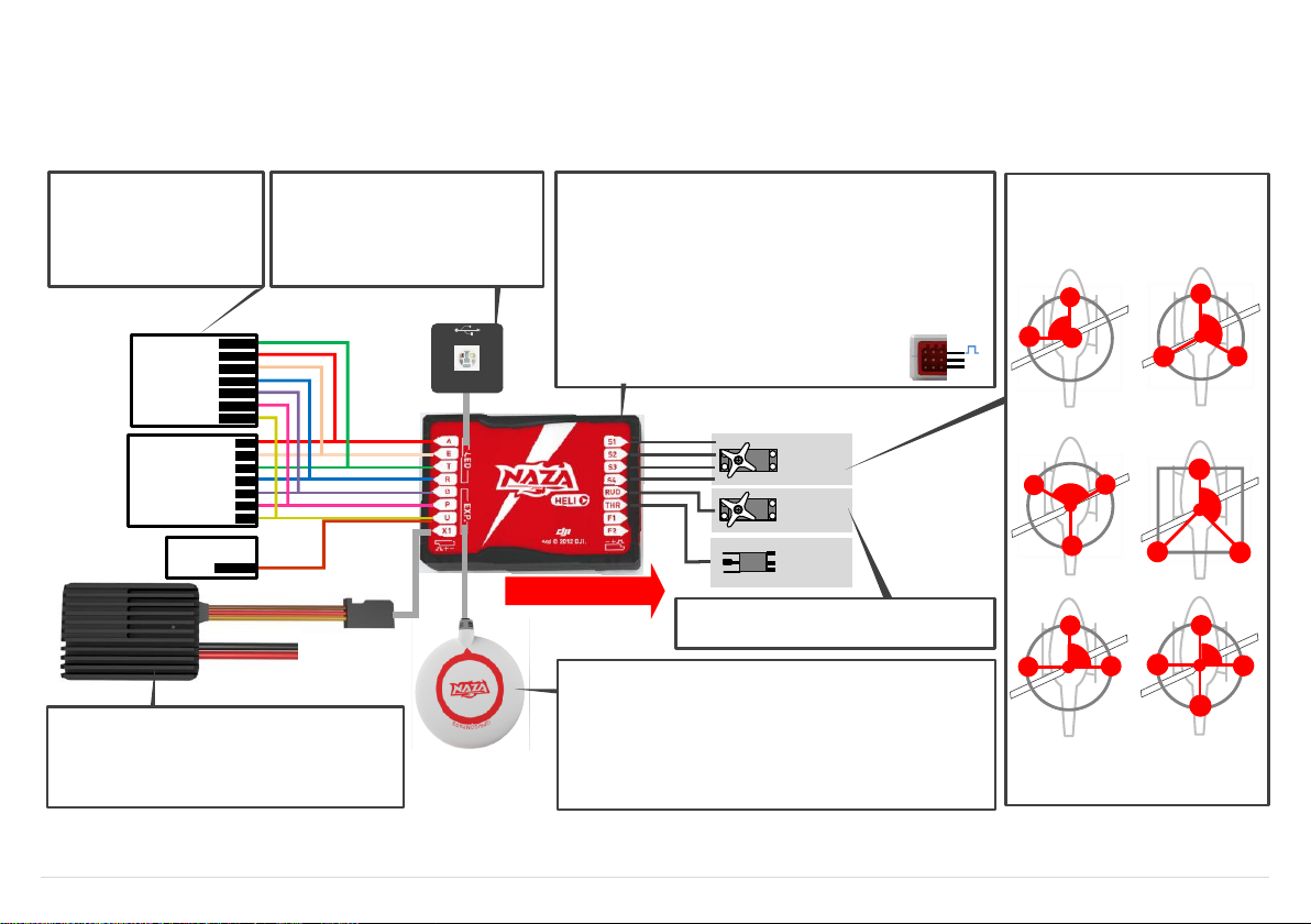
Rudder
Servo
Swashplate
Servo
×3 or 4
ESC
Main Controller(MC)
· Position: the MC is best positioned near the helicopter’s center of gravity,
and make sure all ports are accessible when installing the MC so as to
facilitate wiring.
· Orientation: orient the MC such that the arrow marked on the above, surface
of the MC faces the sky and points directly forward, backward, left or right.
The sides of the MC should be precisely parallel to the helicopter body. DO
NOT MOUNT THE MC UPSIDE-DOWN.
· Mo un t: u se double-sided foam tape for secured installation. Check the
double-sided foam tape or Velcro regularly to ensure that the MC is securely
positioned.
· Note: In three-pin ports, pins near the nicks are signal pins.
MC is NOT water-proof or oil-proof.
LED Indicator
· Mo u nt : moun t the LED module t o the
helicopter, and make sure that you can
see LED indicator during flight.
· Connect: a USB interface Is for configuration
and firmware upgrade by connecting to PC.
Front of MC
+
-
Battey
(Optional)GPS& Compass Module
· Position: mount it on the tail boom, between the head-rotor and the tail-rotor.
The compass is sensitive to magnetic interference, so position the module at
least 20 cm from servos and 30 cm from electric motors. The GPS should not
be close to the main rotor head because rotor blades can interfere with GPS
satellite signal, the farther from the center of the rotor disk, the better.
· Orientation: the NAZA logo marked on the GPS should face the sky, with the
orientation arrow pointing to the helicopter nose direction.
· Mount: use double-sided foam tape for secured installation.
(Optional)BEC
· Conne ct: connect the BEC to the right ports on MC
supplying power for NAZA-H and other electronic devices.
· Toggle switch: slide the switch to 7.4V if high-voltage
servo is used, else to 5.8V if low-voltage servo is used.
R/C System
· Mount: mount the receiver to the
helicopter.
· Connect: connect the receiver to
the right ports on MC.
R/C Receiver
(JR)
R/C Receiver
(Futaba / Hitec)
Futaba S-Bus
S-Bus
1
2
3
4
5
6
7
RUDD
THRO
AILE
ELEV
GEAR
AUX1
AUX2
Optional
Rudder Servo
· Do not connect the rudder servo until the servo type
has been selected in assistant software.
Swash plate Servo
NAZA-H can support the following Sw ash
plate types
Please choose the Swash plate type in the
as si stant s oftwa re acc or ding to your
helicopter.
S2
S1
90
o
S3
H1
S2
S1
S3
120
o
H3
S2
S1
S3
120
o
HR3
S2
S1
S3
140
o
H140
S2
S1
S3
90
o
HE3
S4
S2
S1
S3
90
o
H4
Step1 Assembly
Install the main controller, LED module and receiver to the helicopter, and connect according to the following diagram. GPS &Compass(optional), BEC module (optional).
©2012 DJI Innovations. All Rights Reserved. 4 |
Page 5

STEP1 Please download driver DJI Driver Installer.exe and assistant software from DJI website.
STEP2 Connect the NAZA-H and the PC via USB cable, power on the NAZA-H system.
STEP3 Run DJI Driver Installer.exe, and follow the instructions strictly to finish installation.
STEP4 Run assistant software installer, and follow the instructions strictly to finish installation.
STEP1 Connect the NAZA-H to the PC with a Micro-USB cable. DO NOT break the connection until
setup is finished.
STEP2 Run the NAZA-H Assistant Software。
STEP3 If the communication indicator is on, please double check the connections and driver installation;
otherwise if the indicator is blinking, go to next step.
STEP4 Select InfoSoftware and Firmware. Check whether the assistant software and the firmware
upgrade are available. If available, please upgrade the assistant software and the firmware by
referring to the appendix. Otherwise, go to next step.
STEP5 Select Setup. Please follow step-by-step for your first-time-configuration.
STEP6 Select Common and fill in the required values. You can click the Advanced option for more
parameter settings.
STEP7 Check your R/C transmitter channels through the channel monitor. Monitor the servo battery and
main battery voltages. Choose and set the warning voltage for servo battery and main battery.
Make sure the helicopter parameters set by the setup wizard are correct. Observe the tail gyro
gain settings indicated in the status bar at the bottom of the software window.
Tips:
Please make sure to set the tail gyro gain using the R/C transmitter, using the G channel of NAZA-H main
controller.
Step2 Software and Driver Installation
Step3 Assistant Software Usage
©2012 DJI Innovations. All Rights Reserved. 4 |
Page 6

Step4 Digital Compass Calibration
STEP1 Quickly switch the control mode switch from Manual Mode to GPS ATTI. Mode for 6 to 10 times
(Manual Mode -> GPS ATTI. Mode -> Manual Mode is one time) and the LED indicator will be
constantly on in yellow .
STEP2 Rotate you helicopter around its horizontal axis until the LED lights green constantly.
STEP3 While the green LED is constantly on, hold your helicopter vertically and rotate it around its
vertical axis, keep rotating until the green LED is off, meaning the calibration is finished.
STEP4 After you finished the calibration, the LED indicator will show whether the calibration is successful
or not:
If calibration was successful, calibration mode will exit automatically.
If the LED keeps blinking red quickly, the calibration has failed. Switch the control mode switch
one time to cancel the current calibration, and then re-start from the step 1 for re-calibration.
Important:
Please complete the calibration in an open area.
If you keep having calibration failure, it might suggest that there is very strong magnetic interference
around the GPS & Compass module, please avoid flying in this area.
Please calibrate the compass using the following steps, if the GPS module is used, else skip.
©2012 DJI Innovations. All Rights Reserved. 6 |
Page 7

Step5 Auto Trim Flight Knowledge (Only for Flybarless)
Tips:
Auto Trim flight is only for flybarless types of helicopter.
You may not need to do auto trim flight if the mechanical neutral position is precise enough or only
for normal flight (non 3D).
STEP1 Make sure all connections are correct and connected firmly, and all batteries are fully charged
and then turn on the R/C system.
STEP2 Quickly switch the G channel switch from Tail Locked to Non Tail Locked for 3 to 5 times.
STEP3 The red LED is on and the tail starts the initialization movement, DO NOT moves the helicopter or
the TX sticks during this time.
STEP4 Take-off and hover your helicopter in Manual Mode, using as little R/C transmitter stick movement
as possible during this hover flight.
STEP5 Hover the helicopter for about 1~2 minutes until the red LED turns off, and the system will exit
from the auto trim flight mode.
STEP6 You may now fly your helicopter without power cycling.
Auto Trim flight is to eliminate any bias of the mechanical neutral position, in order to achieve better 3D flight
performance, especially rotation flight performance. Please complete the auto trim flight in calm air weather,
after the first successful test / trim flight and after mechanical adjustment.
©2012 DJI Innovations. All Rights Reserved. 7 |
Page 8

Step6 Control Mode Knowledge
When you use the NAZA-H system, there are three control modes for selection. NAZA-H can work in Manual
Mode and ATTI. Mode without a GPS module. After connection to the GPS module, GPS ATTI. Mode is
available. Please pay attention because the GPS ATTI. Mode is dependent on the number of GPS satellites
acquired by the main controller.
Different control modes will give you different flight performances. Please make sure you understand the
features and differences of the three control modes.
Manual Mode
In Manual Mode, all the operation is the same as normal helicopter, depending on experience.
It is appropriate for 3D flight. Select Manual Mode for Auto Rotation flight.
ATTI. Mode /GPS ATTI. Mode
The Roll and Pitch stick command form the R/C TX corresponds to the Roll and Pitch angle of the
helicopter.
The Yaw stick command form the R/C TX corresponds to the rotation velocity of the helicopter and the
rotation velocity is slower than in Manual Mode.
When you switch to ATTI. Mode or GPS ATTI. Mode, the NAZA will record the hover pitch stick position.
The command of this stick now corresponds to the vertical velocity of the helicopter.
In GPS ATTI. Mode, keep the Tx sticks at the center position, the helicopter will hold position in the
horizontal direction.
When you switch to ATTI. Mode or GPS ATTI. Mode, the NAZA will record the throttle position. The
throttle will hold this position while in ATTI. Mode or GPS ATTI. Mode, so the motor rotation speed
cannot be changed. The motor will not stop even if the throttle stick is at the bottom position. Please
switch to the Manual Mode if you need to change the motor rotate speed or even stop the motor.
Has the function of auto level fail safe and low-voltage alarm.
How to enter the different control mode?
STEP1 Use a 3-position switch on the TX as mode control switch.
STEP2 Make sure to take off the helicopter in Manual Mode in every flight.
STEP3 Hover the helicopter if the Manual Mode flight is normal. Release all joysticks and then flip the
control mode switch to the ATTI. Mode or GPS ATTI. Mode, the Tx stick neutral positions are
recorded automatically.
Note: Do not move any Tx joystick when switching the mode switch, and do not switch the mode
switch while the helicopter is flying inverted.
* This is the standard way to enter the ATTI. Mode and the GPS ATTI. Mode, please refer to the assistant
software for more details.
©2012 DJI Innovations. All Rights Reserved. 8 |
Page 9

Step7 Test Flight
Note:
When the system is powered on, DO NOT move your helicopter or sticks on the R/C transmitter until
the system initialization has finished (about 5 seconds).
Do NOT move any command sticks during the system start and self-check procedure! Please contact
us if the last four green blinks are abnormal.
After power on, if the LED blinks Red, Yellow and Green continually, that means the IMU initialization
and self-checking is abnormal. The NAZA-H will not work, please connect to the Assistant Software
for checking.
You may need to adjust the gain of the tail gyro using the R/C transmitter.
For the first flight of a flybarless helicopter, please finish the Auto Trim flight after you have completed
a successful test / trim flight.
Do not enter ATTI. Mode /GPS ATTI. Mode flight immediately after violent 3Dflight.
Make sure the compass has been calibrated before GPS ATTI. Mode flight.
Read the LED description in the appendix get more accurate understanding of the controller.
Tips:
Please avoid using the system in urban area with many high buildings, tunnels or under bridges, where the
GPS signal is most likely to be lost.
First, carry out Manual Mode Test Flight (Adjust the tail gyro gain in Manual Mode if required.)
STEP1 Make sure all connections are correct and firm, and all batteries are fully charged and then turn on
the R/C transmitter.
STEP2 Place your helicopter on a horizontal surface and power on the NAZA-H and electric devices on the
helicopter, except the brushless motor controller.
STEP3 Check the LED indicator, if red LED blinks quickly & continually, connect to the PC for checking.
STEP4 Slide the control mode switch on your R/C transmitter to make sure it is working properly, refer to the
LED indicator for the MODE selection.
STEP5 If everything is checked without any problems, switch to Manual Mode, move all the sticks on your
R/C transmitter to check that the helicopter is responding correctly to your commands.
STEP6 Take-off and fly your helicopter in Manual Mode.
Select ATTI. Mode Test Flight if Manual Mode Test Flight is successful
STEP7 Hover your helicopter, and switch to ATTI. Mode.
STEP8 Finish and land the helicopter in Manual Mode.
Select GPS ATTI. Mode Test Flight if GPS module is used (Make sure that all the autopilot
parameters have been configured in the Common page of the Assistant Software.)
STEP9 Switch to GPS ATTI. Mode, make sure the green LED is blinking.
STEP10 Red LED maybe blink, which indicates that the NAZA-H is still acquiring GPS satellite signals, wait
STEP11 Switch the system to Manual Mode and take-off and fly your helicopter in Manual Mode.
STEP12 Hover your helicopter, and switch to GPS ATTI. Mode.
STEP13 Finish and land the helicopter in Manual Mode.
until the red LED is off, meaning the NAZA-H have found more than 7 GPS satellites.
©2012 DJI Innovations. All Rights Reserved. 9 |
Page 10

Appendix
STEP1 Make sure your computer is connected to the Internet.
STEP2 Please close all the other applications during the firmware upgrade, including anti-virus software
and firewall.
STEP3 Make sure the power supply is securely connected. DO NOT un-plug the power supply until
firmware upgrade has finished.
STEP4 Connect NAZA-H to PC with Micro-USB cable, DO NOT break connection until firmware upgrade
is finished.
STEP5 Run Software and wait for connection.
STEP6 Select InfoSoftware and Firmware.
STEP7 DJI server will check your current software and firmware version, and get the latest software and
firmware prepared for the unit.
STEP8 If there is a software version more up-to-date than your current version, you will be able to click to
download the new version. Please re-install the assistant software follow the prompts
STEP9 If there is a firmware version more up-to-date than your current version, you will be able to click to
update them. Wait until Assistant software shows “finished”. Click OK and power cycle the unit
after at least 5 seconds.
STEP10 Your unit is now up-to-date.
Note:
After firmware upgrade, please re-configure the NAZA-H using Assistant software.
If the network or DJI server is busy, try again later with above procedures.
If firmware upgrade failed, NAZA-H will enter waiting for firmware upgrade status automatically,
please try again with the above procedures.
You may be asked to register by filling in the contact information before upgrade.
Firmware & Assistant Software Upgrade
Please follow the procedure for software and firmware upgrade; otherwise the NAZA-H might not work
properly.
©2012 DJI Innovations. All Rights Reserved. 10 |
Page 11

Ports Description
MC
A
Stick operation, for cyclic roll or left/right
E
Stick operation, for cyclic pitch or front/back
T
Stick operation, for throttle control
R
Stick operation, for rudder control
G
Switch operation, for gyro sense adjusting
P
Stick operation, for collective pitch or up/down
U
Switch operation, for Control Mode Switch
X1
For Voltage Monitor (Connect to BEC module)
S1
To #1 swashplate servo
S2
To #2 swashplate servo
S3
To #3 swashplate servo
S4
To #4 swashplate servo
THR
To ESC
RUD
To rudder servo
F1
Reserved
F2
Reserved
LED
LED port, for LED wire connection of LED Module
EXP.
GPS port, for GPS module wire connection
LED Module
LED Cable
LED cable, to MC’s LED port
Micro-B USB port: PC connection for configuration and firmware upgrades
BEC Module (Optional)
Switch
A 2-position switch which is selection for high-voltage or low-voltage servos, and
provides voltage detection function at the same time.
7.4V: high-voltage servo
5.8V: low-voltage servo
BEC Cable
To MC X1 port.
Power Supply Cable
For battery connection
©2012 DJI Innovations. All Rights Reserved. 11 |
Page 12

LED Indicator Description
Control Mode (with GPS module)
Manual Mode
ATTI. Mode
GPS ATTI. Mode
GPS satellites < 5
GPS satellites = 5
GPS satellites = 6
GPS satellites > 6
None
Control Mode(without GPS module)
Manual Mode
None
ATTI. Mode.
Flashing indications of ATTI. Mode. and GPS ATTI. Mode are:
Single blink, all sticks are at the center position.
Double blinks, any stick is not at the center position.
Compass Calibration
Begin horizontal calibration
Begin vertical calibration
Calibration / Other error
Auto Trim Flight
Enter Auto Trim Flight
Others
Tx signal lost
Low voltage / Other errors
Connected to PC correctly
System start-up and self-check
DO NOT move any command sticks during the start-up procedure! Please contact us if the last four green
blinks are abnormal.
IMU initialization and
self-checking is abnormal
The NAZA-H will not work, please connect to the Assistant Software for checking.
©2012 DJI Innovations. All Rights Reserved. 12 |
Page 13

Specifications
Mechanical & Electrical Parameters
Part
Size(mm)
Weight
(g)
Operating
temperature
Input
Voltage(V)
Consumption(W)
Specified
Output(W)
MC
45.5×31.5×18.5
25
-10°C ~
50°C
4.8~8.4
1.5 (300mA@5V)
----
BEC
39x 27.5x12.7
37
11 ~52
7.4V: 0.25(10mA@25V)
5.8V: 0.375 (15mA@25V)
37(5A@7.4V)
29 (5A@5.8V)
LED
25 x 25x7
13.4
4.8~8.4
0.3(60mA@5V)
----
GPS
46 (diameter) x9
21.3
4.8~8.4
0.3(60mA@5V)
----
Hardware Functions Supported
Supported Helicopter Types
450,500,600,700 Electric Helicopter
Supported Swashplate Types
H1,120°,140°,Four Servo 90°
Supported Servo Output
Analog 50Hz(1520us center point)
Digital 145Hz (1520us center point)
Tail Servo Output
Analog 50Hz(1520us center point)
Digital 333Hz/560Hz(760us center point)
Digital 125Hz/165Hz/270Hz/333Hz(1520us center point)
Recommended Power Supply
LiPo Battery
Input Channel
8
Output Channel
8
Assistant Software System Requirement
XP 32,64; Win7 32,64; Win8 32,64
Software Functions Supported
Autopilot System
Manual Mode / ATTI. Mode / GPS ATTI. Mode (with GPS module)
Built-In Functions
Tail Gyro
Flybarless supported
Auto Hover or Level Fail Safe
S-Bus Receiver Supported
Low-voltage Alarm (RX voltage and Motor voltage if using the DJI BEC)
Performance Parameters
Performance
Manual Mode
ATTI. Mode
GPS ATTI. Mode
Wind Resistance
----
----
<4 level (By the heli)
Hovering accuracy
----
----
Vertical: ± 0.8m, horizontal:± 2.5m
Flight height limit
R/C range
R/C range
R/C range
Max Yaw Angular Velocity
450 deg/s
130 deg/s
130 deg/s
Max Tilt Angle
None
45 deg
<45 deg(By flight velocity)
Max Ascent / Descent
None (By the heli)
6m/s(By the heli)
6m/s(By the heli)
©2012 DJI Innovations. All Rights Reserved. 13 |
 Loading...