

Page 1
AGRAS
SERIES
User Manual
2018.11
V1.0
Page 2
Searching for Keywords
Search for keywords such as “battery” and “install” to find a topic. If you are using Adobe
Acrobat Reader to read this document, press Ctrl+F on Windows or Command+F on Mac to
begin a search.
Navigating to a Topic
View a complete list of topics in the table of contents. Click on a topic to navigate to that section.
Printing this Document
This document supports high resolution printing.
Page 3
Information
1. The AGRASTM MG-1P / MG-1P RTK does not come with a ight battery. Please purchase the
DJITM Designated Battery (Model: MG-12000P). Read the battery’s safety guidelines and take
necessary precautions when handling to ensure your own safety. DJI assumes no liability for
damage(s) or injuries incurred directly or indirectly from misusing batteries.
2. In this manual, the altitude limit of 30 meters (the altitude limit can be adjusted in the app)
means the altitude between the aircraft and the surface of the objects below it when the altitude
stabilization function of the radar module is enabled. If the function is disabled, the altitude limit
means the altitude between the aircraft and the takeoff point.
Using This Manual
Legend
Important Hints and tips Reference
Before Flight
The following manuals have been produced to help you get the most out of your Agras MG-1P /
MG-1P RTK:
1. In the Box
2. Disclaimer and Safety Guidelines
3. Quick Start Guide
4. User Manual
Refer to In the Box to check the listed parts, and read the Disclaimer and Safety Guidelines before
ight. Refer to the Quick Start Guide to complete assembly and to learn basic operation. Please
refer to the User Manual for more comprehensive information.
Watch the Tutorial Videos
Please watch the tutorial videos at the link below, which demonstrates how to use the
MG-1P / MG-1P RTK safely: http://www.dji.com/mg-1p/info#video
Download DJI Assistant 2 for MG
Download DJI ASSISTANTTM 2 for MG from:
http://www.dji.com/mg-1p/info#downloads
The operating temperature of this product is 0° to 40° C. It does not meet the standard
operating temperature for military grade application (-55° to 125° C), which is required to
endure greater environmental variability. Operate the product appropriately and only for
applications that it meets the operating temperature range requirements of that grade.
© 2018 DJI All Rights Reserved.
1
Page 4

Safety at a Glance
1. Pesticide Usage
• Avoid the use of powder pesticides as
much as possible or else they may reduce
the service life of the spraying system.
• Pesticides are poisonous and pose serious
risks to human safety. Please use them in
The Agras MG-1P / Agras MG-1P RTK
(abbreviated as “MG-1P” / “MG-1P RTK”)
aircraft is NOT a toy and is not suitable
for children under the age of 18.
Note that ‘Safety at a Glance’ only provides a quick
overview of the safety tips. Make sure you read
and understand the remaining sections of this
document and the User Manual.
strict accordance with their specications.
• Residue on the equipment caused by splashes or spills when pouring and mixing the pesticide
can irritate your skin. Be sure to clean the equipment after mixing.
• Use clean water to mix the pesticide to avoid blocking the strainer. Clear any blockages before
using the equipment.
• Wear protective clothing to prevent direct body contact with the pesticide. Always rinse
your hands and skin after handling pesticides. Clean the aircraft and remote controller after
applying the pesticide.
• Effective use of pesticides relies on pesticide density, spray rate, spray distance, aircraft
speed, wind speed and wind direction. Consider all factors when using pesticides, but NEVER
compromise the safety of people, animals and the environment in doing so.
• DO NOT contaminate rivers and sources of drinking water.
2. Environmental Considerations
• Always y at locations that are clear of building and other obstacles.
• DO NOT y above or near large crowds.
• Avoid ying at altitudes above 98 feet (30 m).
• Be very careful when ying over 6,560 feet (2,000 m) above sea level.
• Fly in moderate weather conditions with temperatures between 32° to 104° F (0° to 40° C).
• Ensure that your operations do not violate any applicable laws or regulations, and that you
have obtained all appropriate prior authorizations. Consult the relevant government agency
or authority, or your lawyer before ight to ensure you comply with all relevant laws and
regulations.
• DO NOT operate any parts of the aircraft indoors.
3. Pre-ight Checklist
• Remote controller and aircraft batteries are fully charged.
• Landing gear and spray tank are rmly in place.
• All screws are rmly tightened.
• Propellers and frame arms are unfolded, and arm sleeves are rmly tightened.
• Propellers are in good condition and rmly tightened.
• There is nothing obstructing the motors.
© 2018 DJI All Rights Reserved.
2
Page 5

AGRAS MG-1P SERIES User Manual
• Spraying system is without any blockage and works properly.
• Compass is calibrated at every new ight location.
4. Operation
• Stay away from the rotating propellers and motors.
• The takeoff weight must not exceed 24.8 kg (taking off at sea level).
• Maintain a visual line of sight (VLOS) to your aircraft at all times.
• DO NOT use the Combination Stick Command (CSC) or other methods to stop the motors
when the aircraft is airborne unless in an emergency situation.
• DO NOT answer incoming calls during ight.
• DO NOT y under the inuence of alcohol or drugs.
• During the Return to Home procedure, if the operating environment is not suitable for the radar
module to work properly, the aircraft will not be able to avoid obstacles. You can adjust the
ight speed and altitude to avoid obstacles if the remote controller is connected to the aircraft.
• In the instance of a Low Battery Warning, land the aircraft at a safe location.
• After landing, rst stop the motors, then power off the aircraft, and then turn off the remote
controller. Otherwise, the aircraft may enter Failsafe RTH automatically due to remote controller
signal loss.
• Please maintain full control of the aircraft at all times and do not rely on the DJI MG app. The
obstacle avoidance function is disabled in certain situations. Please keep the aircraft within
your visual line of sight and visually observe the ight. Please use your sound discretion
to operate the aircraft and avoid obstacles timely and manually. It is important to set an
appropriate Failsafe and Return to Home altitude before each ight.
5. Maintenance and Upkeep
• DO NOT use aged, chipped or broken propellers.
• Remove or empty the spray tank during transportation or when not in use to avoid damaging
the landing gear.
• Recommended storage temperature (empty spray tank): between -4° and 104° F (-20° and 40° C).
• Clean the aircraft immediately after spraying.
• Inspect the aircraft every 100 ights or after ying for over 20 hours.
• For more maintenance guidelines, refer to the Product Care section in this document.
6. Observe Local Laws and Regulations
• You can nd a list of DJI GEO Zones at http://www.dji.com/ysafe.
• The DJI GEO Zones is not a replacement for local government regulations or good judgment.
• Avoid ying in areas where rescue teams are actively using the airspace.
© 2018 DJI All Rights Reserved.
3
Page 6
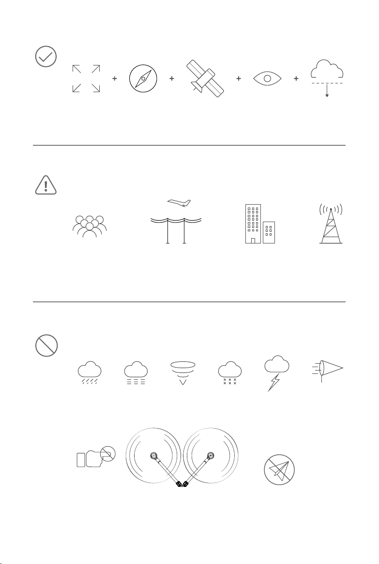
30 m
Fly in Open Areas Calibrate the
Avoid ying over or near crowds, high voltage power lines or bodies of water.
Strong electromagnetic sources such as power lines, base stations, and tall buildings may affect the
onboard compass. It is recommended to use MG-1P RTK. Always stay alert about surroundings in ight.
Compass
Strong GNSS Signal VLOS Fly Below
98 feet (30 m)
≥8 m/s
DO NOT use the aircraft in adverse weather conditions such as rain (precipitation rate exceeding 25 mm
or 0.98 inches in 12 hours), wind speeds exceeding 8 m/s or 17 mph (28 kph), fog, snow, and lightning.
© 2018 DJI All Rights Reserved.
4
Stay away from the rotating
propellers and motors.
GEO Zones
Learn more at:
https://www.dji.com/ysafe
Page 7

Contents
Information
Using This Manual
Legend
Before Flight
Watch the Tutorial Videos
Download DJI Assistant 2 for MG
Safety at a Glance
Product Prole
Introduction
Feature Highlights
Overview
Installation
Mounting the Landing Gear
Mounting the Power Port Module
Mounting the Spray Tank
Unfolding the Frame Arms
Mounting the Sprinklers
Mounting the Radar Module
Mounting the Remote Controller Battery
Mounting the Flight Battery
Mounting the Dongle
1
1
1
1
1
1
2
7
7
7
8
11
11
12
12
13
14
15
16
16
17
Remote Controller
Prole
Using the Remote Controller
Remote Controller LEDs
Multi-Aircraft Control Function
Linking the Remote Controller
DJI MG App
Main Screen
Operation View
© 2018 DJI All Rights Reserved.
17
17
18
23
24
24
26
26
27
5
Page 8

AGRAS MG-1P SERIES User Manual
Aircraft
Prole
Flight Modes
Operation Modes
Operation Resumption
System Data Protection
Radar Module
Empty Tank
Return to Home (RTH)
Low Battery Warnings
RTK Functions (for MG-1P RTK only)
Flight
Operation Environment
Flight Limits and No-Fly Zones
Pre-Flight Checklist
Calibrating the Compass
Calibrating the Spraying System
Starting and Stopping the Motors
Flight Test
DJI Assistant 2 for MG
Installation and Launching
Using DJI Assistant 2 for MG
30
30
30
30
36
38
38
40
40
43
43
44
44
44
46
46
47
48
49
50
50
50
Appendix
Specications
Aircraft Status Indicators Description
Updating the Firmware
© 2018 DJI All Rights Reserved.
6
51
51
54
54
Page 9

Product Prole
Introduction
The Agras MG-1P series (MG-1P / MG-1P RTK) aircraft are equipped with a wide-angle First Person
View (FPV) camera which enables observation of the landscape in front of the aircraft, allowing
operation areas to be identied and enabling pilots to avoid obstacles. Its second generation high-
precision radar with integrated obstacle avoidance radar module and forward, backward, and
downward altitude stabilization radar modules provides improved obstacle sensing and terrain
following capabilities. The quality of the aircraft’s industrial design and materials make it dust-proof,
water-proof (IP43 protection rating, IEC standard 60529), and corrosion-resistant. The MG-1P and
MG-1P RTK utilize DJI’s dedicated A3 ight control system with eight-rotor propulsion redundancy,
ensuring safe and stable operation at all times. The MG-1P RTK has a built-in DJI Onboard D-RTK
which provides more accurate data for centimeter-level positioning*.
The remote controller uses the DJI OCUSYNC
control distance of up to 3.11 mi (5 km)*, and is equipped with a bright, dedicated screen with the
DJI MG app built-in. Operation planning can be performed either using the remote controller only
or by ying the aircraft to waypoints. The Banked Turning feature in the DJI MG app commands the
aircraft to take corners without fully stopping, making ight operations more exible and efcient.
The remote controller’s Multi-Aircraft Control mode can be used to coordinate the operation of up to
ve aircraft at the same time, enabling pilots to work very efciently. Replaceable batteries make it
easy to use the remote controller every day and removable antennas make maintenance easier.
TM
dual-band video downlink system, has a maximum
Feature Highlights
The MG-1P / MG-1P RTK uses a DJI dedicated ight control system, providing four operation modes:
Route, A-B Route, Manual, and Manual Plus.
The DJI MG app automatically produces ight routes based on your planned elds. Plan a eld by
walking with the remote controller or by ying the aircraft to waypoints. To start, simply select the eld
from the eld list.
In A-B Route operation mode, the aircraft will travel along a pre-planned route and spray its liquid
payload. Users can set the line spacing, ying speed, and other parameters.
In Manual operation mode, users can start and stop spraying manually and also adjust the spray rate.
In Manual Plus operation mode, flight speed is restricted and heading is locked. Except for the
heading, users can control the aircraft's movement via control sticks. Press button C1/C2 on the
remote controller or the corresponding button in the app and the aircraft will y one line spacing to the
left/right. (This is the default function for button C1 and button C2. They are customizable in the app.)
The MG-1P / MG-1P RTK also includes the Operation Resumption function. When pausing the
operation in Route or A-B Route operation mode, Operation Resumption records a breakpoint for the
aircraft. Users can resume from the return point when continuing the operation.
TM
,
* This should be used with a DJI approved Network RTK service or a DJI D-RTK 2 GNSS High-Precision Mobile Station (sold
separately). Refer to RTK Functions (p. 43) for details.
The remote controller is able to reach its maximum transmission distance (FCC: 3.11 mi (5 km); CE / KCC / MIC / SRRC: 1.86
mi (3 km)) in a wide open area with no electromagnetic interference, and at an altitude of about 8.2 ft (2.5 m).
© 2018 DJI All Rights Reserved.
7
Page 10
AGRAS MG-1P SERIES User Manual
The remote controller features Multi-Aircraft Control mode, which can be used to coordinate the
operation of up to five aircraft simultaneously. Turn the Aircraft Control Switch Dial on the remote
controller to switch control between the different aircraft.
The second generation high-precision radar mode works automatically in Route, A-B Route, and
Manual Plus operation mode. Altitude detection and stabilization functions are available in forward,
backward, and downward directions while the obstacle avoidance function is available in forward or
backward direction according to the direction of ight.
The spraying system includes a spray tank, liquid level meter, sprinklers, and other accessories. The
four sprinklers placed on the aircraft’s two sides provide evenly distributed spraying and coverage
of the liquid payload. Optimized structures and algorithms of the spraying system for more precise
spraying control and more effective leak and drip prevention.
The MG-1P RTK has a built-in DJI Onboard D-RTK, providing more accurate data for centimeterlevel positioning when used with the DJI D-RTK 2 or Network RTK Service. An optional Handheld
RTK or PC GS Pro is available for more precise eld planning, enhancing the accuracy of agricultural
operations.
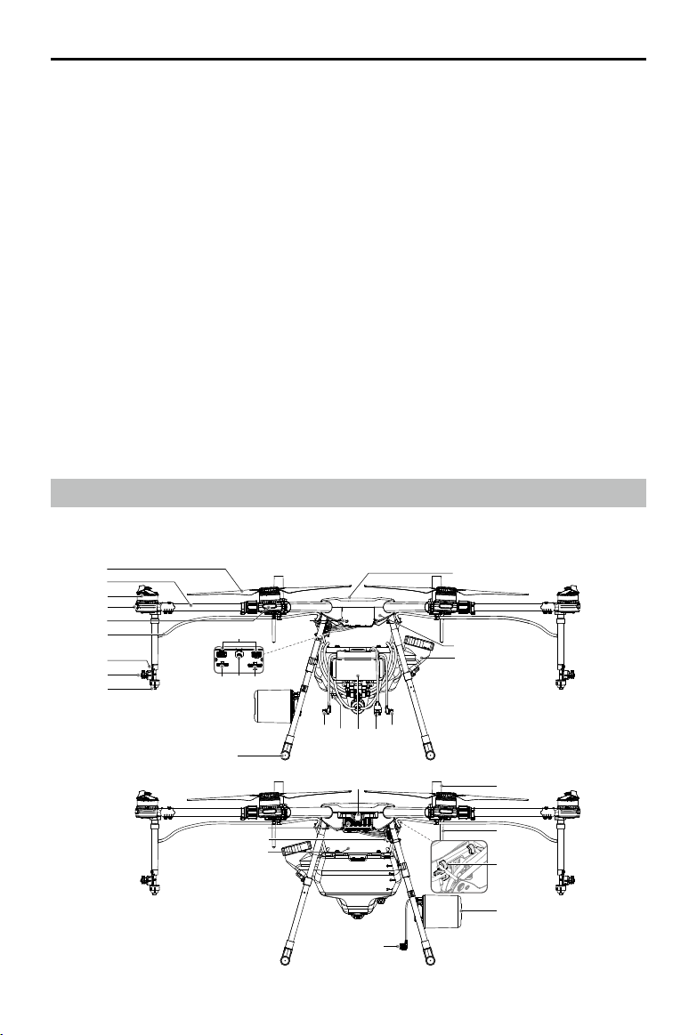
Overview
Aircraft
1
2
3
4
5
6
7
8
9
© 2018 DJI All Rights Reserved.
8
12 1413
15
22
11
10
21
20
16 16191817
23
24
25
26
27
Rear View
31
30
29
28
Front View
Page 11
AGRAS MG-1P SERIES User Manual
1 Propellers
2 Frame Arms
3 Motors
4 ESC LEDs
(on M1-M4 and M7-M8 arms)
5 Aircraft Status Indicators
(on M5-M6 arms)
6 Hoses
7 Sprinklers
8 Manual Relief Valve
9 Nozzles
10 Link Button
DO NOT obstruct the GNSS module (located at the center of the aircraft), as doing so would
reduce the GNSS signal strength.
The MG-1P and MG-1P RTK do not come with a battery. Please purchase the DJI approved
battery pack (Model: MG-12000P).
11 Pump Ports
12 Radar Port
13 Micro USB Port
14 Liquid Level Meter Port
15 Landing Gear
16 Pump Cables
17 Liquid Level Meter
18 Delivery Pumps
19 Liquid Level Meter Cable
20 Spray Tank
21 Aircraft Body
22 GNSS Module
23 FPV Camera
24 Intake Vent
25 Power Port
26 Battery Compartment
27 Radar Cable
28 Radar Module
29 Remote Controller Holder
30 OCUSYNCTM Dual-band
Antennas
31 Onboard D-RTK Antennas
(on MG-1P RTK only)
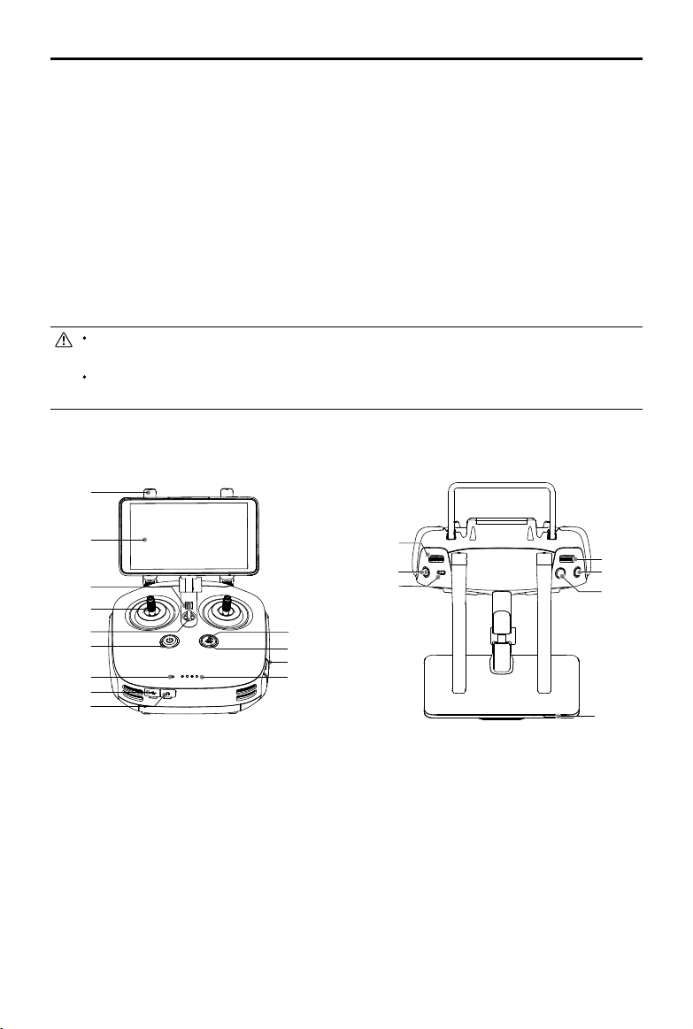
Remote Controller
1
2
3
4
5
6
7
13
12
11
10
8
9
14
15
16
20
19
18
17
1 Antennas
Relays aircraft control signals.
2 Display Device
Android-based to run the DJI MG app.
3 Speaker
Audio output.
4 Control Sticks
Controls aircraft movement. Can be set to
Mode 1, Mode 2, or a custom mode.
5 Lanyard Attachment
Used to attach the remote controller lanyard.
6 Power Button
Used to turn the remote controller on and off.
7 Status LED
Indicates whether the remote controller is
linked to the aircraft.
8 USB-C Port
Connects to a computer via a USB-C cable
for conguration. Connects to the aircraft via
a USB-C OTG cable and a Micro USB cable
for aircraft rmware update.
© 2018 DJI All Rights Reserved.
9
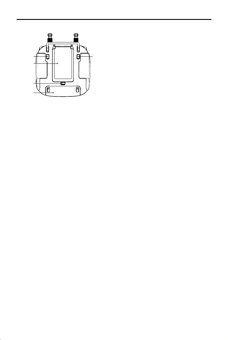
Page 12
AGRAS MG-1P SERIES User Manual
22
21
23
24
25
9 3.5 mm Audio Jack
Used to connect an audio input/output
device.
10 Battery Level LEDs
Displays current battery level.
11 MicroSD Card Slot
Provides display device with up to 128 GB
of extra storage.
12 RTH Status LED
Circular LED around the RTH button.
Displays RTH status.
13 RTH Button
Press and hold this button to initiate Return
to Home (RTH).
14 Spray Rate Dial
Turn to adjust the spray rate in Manual
operation modes.
15 Spray Button
Press to start/stop spraying in Manual
operation mode.
16 Pause Switch
Toggle to pause the operation in Route, A-B
Route or Manual Plus operation modes.
During RTH, toggle to pause RTH. The
aircraft hovers, and then the aircraft can
be controlled manually.
17 Sleep/Wake Button
Press to sleep/wake the screen; press and
hold to restart.
18 Button A
Records Point A of the operation route in A-B
Route operations by default. Use the app to
customize the button.
19 Button B
Records Point B of the operation route in A-B
Route operations by default. Use the app to
customize the button.
20 Aircraft Control Switch Dial
Turn and press the dial to switch among
the aircraft when using Multi-Aircraft Control
function.
21 Button C1
When you are planning a eld, it starts
or ends obstacle measurement. When
planning a eld, the function cannot be
customized. When you are not planning a
eld, the default function is Map/FPV Switch.
Use the app to customize the button.
22 Button C2
When you are planning a eld, it adds
a waypoint. When planning a eld, the
function cannot be customized. When you
are not planning a eld, then the default
function is Delete Route. Use the app to
customize the button.
23 Battery Compartment Cover
Open the cover to mount or remove the
Intelligent Battery from the remote controller.
24 Battery Compartment Cover Lock
Slide the lock down to open the cover.
25 Dongle Compartment Cover
Open the cover to mount or remove the
dongle.
© 2018 DJI All Rights Reserved.
10
Page 13
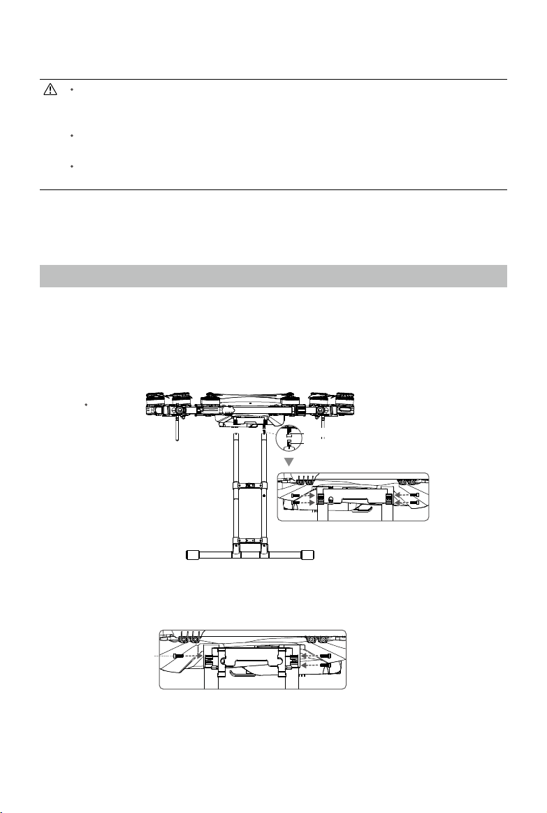
Installation
Threadlocker of medium strength is required for installation. Apply threadlocker when
mounting the landing gear, power port module, spray tank, sprinklers, and radar module.
Ensure the threadlocker is totally dry and solid before ight.
DO NOT bend the hoses in an arc tighter than their minimum bend radius during
installation. This is to avoid creasing, which may compromise the spraying effect.
Ensure that all installation and connection procedures are completed before powering on
the aircraft.
The installation steps are the same for both the MG-1P and MG-1P RTK. In the gures below the
MG-1P is shown.
Mounting the Landing Gear
1. Identify the landing gear leg containing the compass cable.
2. Take out the compass cable from the tube of the landing gear leg and connect it to the compass
port on the aircraft’s right side, then mount the right landing gear leg to the mounting position.
Be careful not to damage the cable.
3. Secure the right landing gear leg in place using four M3×10 screws.
Aircraft Rear
Compass Port
Compass Cable
4. Mount the left landing gear leg and secure it in place using three M3×10 screws.
Insert into the upper
screw hole
© 2018 DJI All Rights Reserved.
11
Page 14
AGRAS MG-1P SERIES User Manual
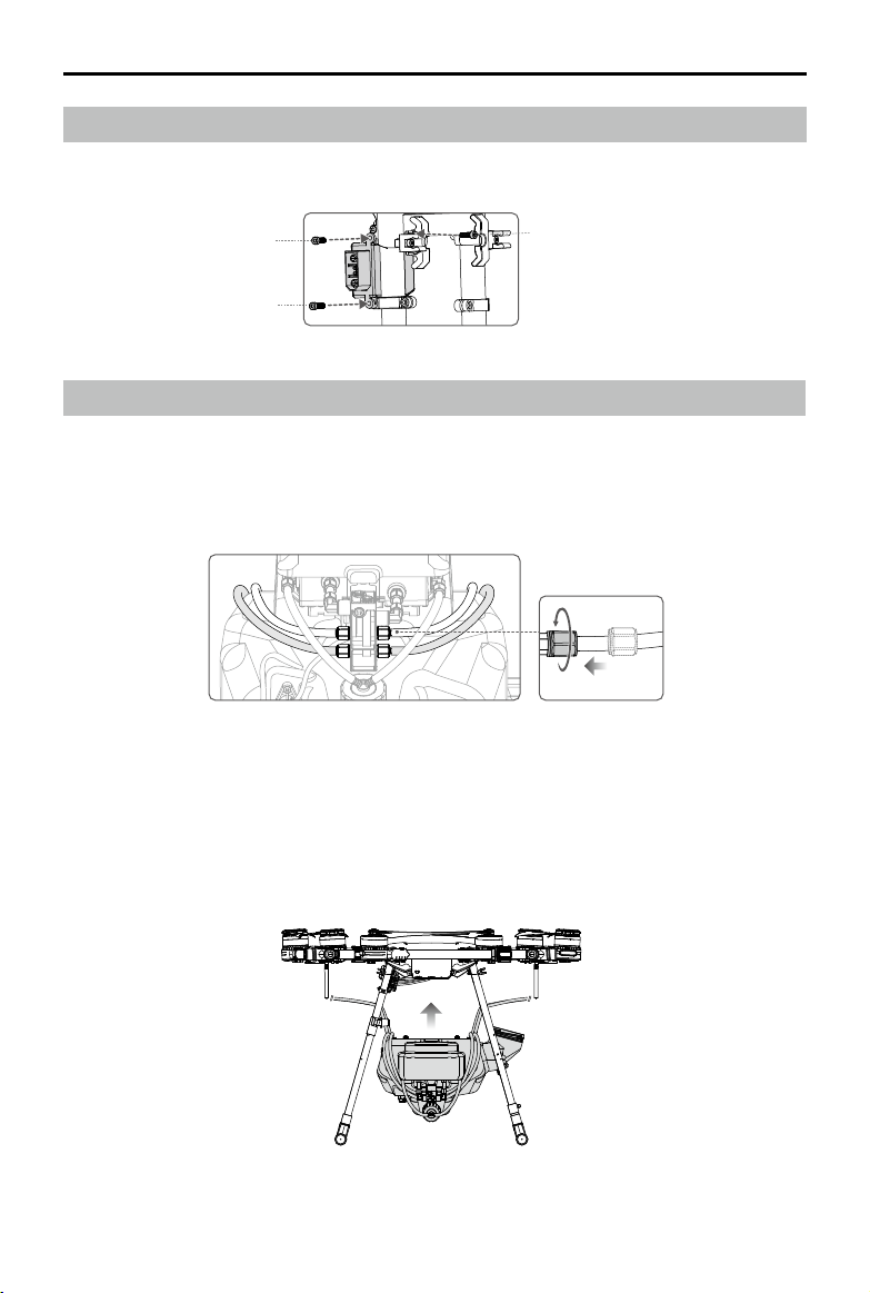
Mounting the Power Port Module
Mount the power port module onto the left landing gear leg using two M3×18 screws and one
M3×22 screw.
M3×18
M3×22
M3×18
Mounting the Spray Tank
1. Connect the sprinkler kits to the spray tank: Pull the four hoses through the nuts to the outlets
under the delivery pump, then tighten the nuts using a wrench. Note that the white and black
hoses should be attached to outlets with labels of the same color. Be sure to securely tighten the
nuts to avoid liquid leakage.
2. Remove the cover of the spray tank. Pull the hoses on both sides through the spaces between
the two tubes of each landing gear leg with the mouth of the tank facing toward the right side of
the aircraft.
3. Lift the spray tank and pull the mouth of the tank through the space between the two tubes of the
right landing gear leg.
© 2018 DJI All Rights Reserved.
12
Page 15
AGRAS MG-1P SERIES User Manual
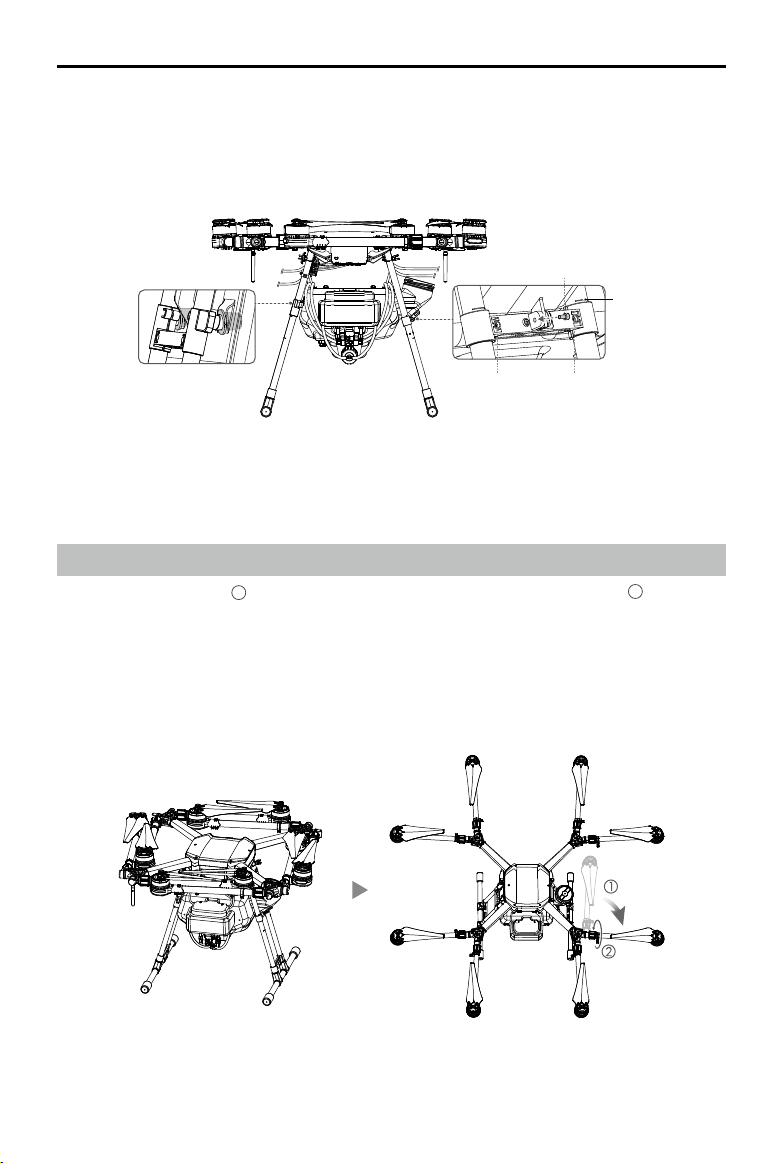
4. Insert the plugs on the left landing gear leg into the mounting holes on the spray tank.
5. Slide the xing bracket on the right landing gear leg to the marks on the tubes to align the screw
holes on the xing bracket with the n on the right side of the spray tank. Tighten the two M3×12
screws and insert and tighten one M3×10 (Plus) screw.
M3×10 (Plus)
Marks
M3×12M3×12
6. Connect the two pump cables and one liquid level meter cable to their corresponding ports on
the aircraft body.
Unfolding the Frame Arms
1. Unfold the frame arms 1 and tighten the two arm sleeves at each of the junctions 2.
2. Identify the position and rotational direction of the motors. The top view shows motors M1 to M8
arranged in a counter-clockwise order, with motors M1 and M2 at the front of the aircraft, and
motors M5 and M6 at the rear. Motors M1, M3, M5, and M7 rotate counter-clockwise as indicated
by the “CCW” mark, while motors M2, M4, M6, and M8 rotate clockwise as indicated by the “CW”
mark.
M3
M4
M1M2
M5 M6
© 2018 DJI All Rights Reserved.
M8
M7
13
Page 16
AGRAS MG-1P SERIES User Manual
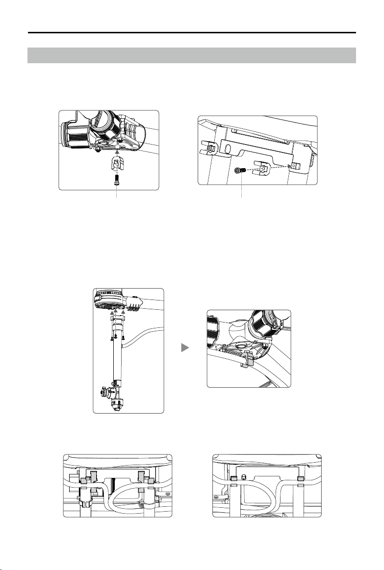
Mounting the Sprinklers
1. Mount the hose clips: Mount one hose clip to the bottom of each of the four frame arm junctions
using T3×10 screws. Mount one hose clip to the outside of the right landing gear leg mounting
position using an M3×6 screw.
M3×6T3×10
2. Mount the sprinklers with white hoses under motors M3 and M8 (with white circle marks). Mount
the sprinklers with black hoses under motors M4 and M7 (with black circle marks). Mount each
of the four sprinklers using three M3×8 (Plus) screws, then insert the hoses into the clips at the
bottom of the frame arm junctions. Be sure to mount the sprinklers to the mounting holes nearer
to the inside of the aircraft, with the hoses facing the frame arm.
3. Insert the hoses on both sides into the clips on the landing gear.
© 2018 DJI All Rights Reserved.
14
Page 17
AGRAS MG-1P SERIES User Manual
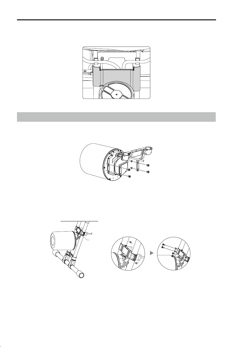
4. Mount the fender to the right landing gear leg to avoid spills when pouring liquids. Handle with
care to avoid damage to the fender.
Mounting the Radar Module
1. Mount the radar bracket to the radar module using four M3×5.5 screws, with the bracket
crossbar over the radar cable as shown in the gure below.
2. Unfasten the buckles on the bracket then mount it to the left landing gear leg. Align the bracket
to the lower marks on the landing gear leg. Fasten the buckles and secure them using four
M3×5.5 screws.
Marks
3. Insert the radar cable into the cable clip on the landing gear leg, then connect it to the radar port
on the aircraft body.
© 2018 DJI All Rights Reserved.
15
Page 18
AGRAS MG-1P SERIES User Manual
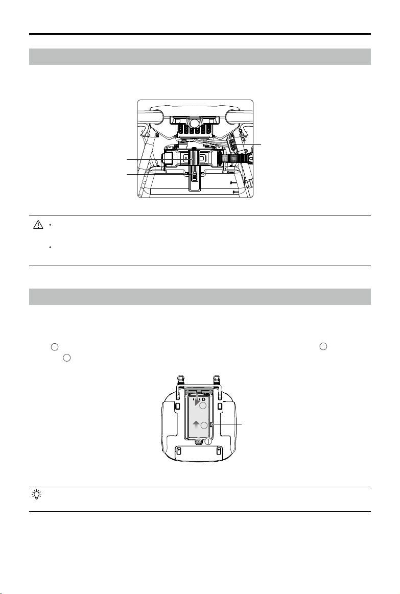
Mounting the Flight Battery
Insert the battery into the battery compartment from the front of the aircraft. Ensure the battery is
securely mounted and then fasten the belt to the stud on the spray tank.
Power Port
Belt
Stud
The MG-1P and MG-1P RTK do not come with a battery. Please purchase the DJI
approved MG-1P battery pack (Model: MG-12000P).
The voltage on the aircraft can reach 50.4 V. Read the battery’s safety guidelines and take
necessary precautions when handling the battery to ensure your own safety.
Mounting the Remote Controller Battery
The remote controller uses a removable, interchangeable Intelligent Battery making long-term
operation easy.
Slide the battery compartment cover lock on the back of the remote controller down to open the
1
, insert the Intelligent Battery into the compartment and push it to the top 2 , then close
cover
3
the cover
.
3
2
Battery Release Button
To remove the Intelligent Battery, open the cover, press and hold the battery release button,
then push the battery downward.
© 2018 DJI All Rights Reserved.
16
Page 19

AGRAS MG-1P SERIES User Manual
Mounting the Dongle
Only use a DJI approved dongle.
The dongle supports various network standards. Use a SIM card that is compatible with
the chosen mobile network provider and select a mobile data plan according to the
planned level of usage.
Use the dongle and the SIM card in accordance with their manuals.
The dongle and SIM card are used to enable the remote controller to access to specic
networks and platforms, such as the DJI Agriculture Management Platform. Be sure to
mount them correctly, or else network access will not be available.
1. Lift the dongle compartment cover at the gap at its lower right corner, then remove it.
2. Insert the SIM card into the dongle and then insert the dongle into the USB port inside the
compartment. Test to ensure that they function properly.*
3. Cut the connecting string between the dongle cap and dongle body if there is one.
4. Re-mount the dongle compartment cover. To secure the cover, open the silicone protectors on
the cover, insert and tighten two M1.6×3 screws, then close the silicone protectors.
Test procedure: Press the remote controller power button once, then press again and hold to turn the remote controller on.
*
In the DJI MG app tap and select Network Diagnostics. If the statuses of all the devices in the network chain are shown
in green the dongle and SIM card are functioning properly.
Remote Controller
Prole
The remote controller uses the DJI OcuSync dual-band video downlink system, has a maximum
control distance of up to 3.11 mi (5 km). It includes a dedicated, Android-based display that runs
the DJI MG app independently for operation planning and aircraft status display. Its Multi-Aircraft
Control mode can be used to coordinate the operation of up to five aircraft at the same time to
improve operation efciency.
Stick mode can be set to Mode 1, Mode 2, and Mode 3, or to a custom mode in the DJI MG
app. It is recommended to set it to Mode 2 for beginners.
Mode 1: The right stick serves as the throttle.
Mode 2: The left stick serves as the throttle.
© 2018 DJI All Rights Reserved.
17
Page 20

AGRAS MG-1P SERIES User Manual
Using the Remote Controller
Turning the Remote Controller On and Off
The remote controller uses a removable, interchangeable Intelligent Battery. The battery level is
indicated via the Battery Level LEDs on the front panel after the battery is mounted. Follow the steps
below to turn on your remote controller:
1. When the remote controller is turned off, press the Power button
once to check the current battery level, indicated by the Battery
Level LEDs. If the battery level is too low, recharge before use.
2. Press the Power button once. Then press and hold to turn on
the remote controller.
3. The remote controller will beep when turned on. The Status LED
will rapidly blink green, indicating that the remote controller is
linking to the aircraft. They will glow solid green when linking is
complete.
4. Repeat Step 2 to turn off the remote controller.
The remote controller internal backup battery allows users to insert and remove the external
Intelligent Battery while the remote controller is still on and in use. The device will enter Sleep
Mode to save power. Users are then required to replace the Intelligent Battery within three
minutes, or the remote controller will power off.
Charging the Remote Controller
Charge the remote controller Intelligent Battery using the included AC power adapter and Charging
Hub.
1. Place the battery into the Charging Hub, connect the AC power adapter to the Charging Hub,
and then connect the charger to a power outlet (100-240V, 50/60Hz).
2. The Charging Hub will intelligently charge batteries in sequence according to battery power
levels from high to low.
3. The Status LED blinks green when charging and turns solid green when fully charged. The
buzzer will begin beeping when charging is complete. Remove the battery or turn off the buzzer
to stop it.
© 2018 DJI All Rights Reserved.
18
Power Outlet
AC Power AdapterCharging Hub
Page 21

AGRAS MG-1P SERIES User Manual
Operating the Aircraft
This section explains how to control the orientation of the aircraft through the remote controller.
Control can be set to Mode 1, Mode 2 or Mode 3, or to a custom mode.
Mode 1
Mode 2
Mode 3
Left Stick
Forward
Backward
Turn RightTurn Left
Right Stick
Right StickLeft Stick
UP
Down
Turn RightTurn Left
Left Stick Right Stick
Forward
UP
Down
RightLeft
Forward
Backward
RightLeft
UP
Backward
Down
RightLeft
© 2018 DJI All Rights Reserved.
Turn RightTurn Left
19
Page 22

AGRAS MG-1P SERIES User Manual
For example, the following description uses Mode 2:
Remote
Controller
(Mode 2)
Aircraft
(
Indicates nose direction)
Remarks
Throttle Stick: Vertical movement of the
left stick controls the aircraft’s elevation.
Push up to ascend and push down to
descend. Use the left stick to take off
when the motors are spinning at idle
speed. The aircraft will hover in place
if the stick is in the center position. The
farther the stick is pushed away from the
center position, the faster the aircraft will
change elevation.
Yaw Stick: Horizontal movement of
the left stick controls the aircraft's
heading. Push left to rotate the aircraft
counterclockwise and push right to
rotate clockwise. The aircraft will hover in
place if the stick is in the center position.
The farther the stick is pushed away from
the center position, the faster the aircraft
will rotate.
Pitch Stick: Vertical movement of the
right stick controls the aircraft’s pitch.
Push up to y forwards and press down
to y backwards. The aircraft will hover in
place if the stick is in the center position.
Push the stick farther for a larger pitch
angle and faster ight.
© 2018 DJI All Rights Reserved.
20
Roll Stick: Horizontal movement of the
right stick controls the aircraft’s roll. Push
the stick left to y left and right to y right.
The aircraft will hover in place if the stick
is in the central position. Push the stick
farther for a larger roll angle and faster
ight.
Page 23

AGRAS MG-1P SERIES User Manual
Controlling the Spraying System
Complete an operation remotely via the Spray Rate or Aircraft Control Switch dials, or the Spray, A/B,
and C1/C2 buttons.
1
2
3
6
5
4
8
7
1 Spray Rate Dial
In Manual or Manual Plus operation mode, turn left to reduce and right to increase the spray rate*.
The DJI MG app will indicate the current spray rate.
* Spray rate may vary according to the nozzle model and viscosity of the liquid.
2 Spray Button
In Manual operation mode, press to start or stop spraying.
3 Pause Switch
Toggle to pause the operation in Route or A-B Route operation modes. The aircraft hovers and
records the breakpoint, and then the aircraft can be controlled manually. To resume a Route
operation, select the operation in the app. To resume an A-B Route operation, tap Resume on the
screen. Then the aircraft returns to the breakpoint automatically and continues the operation.
During RTH, toggle to pause RTH. The aircraft hovers, and then the aircraft can be controlled
manually.
4 Button A
Records Point A of the operation route in A-B Route operations by default. Use the app to
customize the button.
5 Button B
Records Point B of the operation route in A-B Route operations by default. Use the app to
customize the button.
6 Aircraft Control Switch Dial
Turn and press the dial to switch among the aircraft when using Multi-Aircraft Control function.
7 Button C1
When you are planning a eld, it starts or ends obstacle measurement. When planning a eld, the
function cannot be customized. When you are not planning a eld, the default function is Map/
FPV Switch. Use the app to customize the button.
© 2018 DJI All Rights Reserved.
21
Page 24

AGRAS MG-1P SERIES User Manual
8 Button C2
When you are planning a eld, it adds a waypoint. When planning a eld, the function cannot be
customized. When you are not planning a eld, then the default function is Delete Route. Use the
app to customize the button.
The table below is a summary for how to control the spraying system via the remote controller in
different modes.
Spray
Spray
Mode
Route
operation
mode
A-B Route
operation
mode
Manual
operation
mode
Manual Plus
operation
mode
Field Plan / / / / / /
Rate Dial
/ / Pause Customizable Customizable
/ / Pause Customizable Customizable / Customizable Customizable
Adjust
spray rate
Adjust
maximum
spray rate
Pause
Button
Start
or stop
spraying
/ / Customizable Customizable / Customizable Customizable
Button A Button B
Switch
/ Customizable Customizable / Customizable Customizable
Aircraft
Control
Switch Dial
Switch
between
aircraft
Button C1 Button C2
Customizable Customizable
Start or end
obstacle
measurement
Add a waypoint
RTH Button
Press and hold the RTH button to bring the aircraft back to the last recorded Home Point. The LED
around the RTH Button will blink white during RTH procedure. Users can control aircraft heading
while it ies to the Home Point. Press this button again to cancel RTH and regain control of the
aircraft.
© 2018 DJI All Rights Reserved.
22
Page 25

Optimal Transmission Zone
AGRAS MG-1P SERIES User Manual
Strong
Try to keep the aircraft inside the optimal transmission zone. If the signal is weak, adjust the
antennas or y the aircraft closer.
Weak
Optimal Transmission Zone
Remote Controller LEDs
RTH Status LED
Status LED
The Status LED indicates the connection status between the remote controller and the aircraft. The
RTH Status LED indicates the Return to Home status of the aircraft. See the table below for details
on these indicators:
Status LED Sound Remote Controller Status
— Solid Red chime
— Solid Green chime
Blinks Red Repeating slow beep Remote controller error.
RTH Status LED Sound Aircraft Status
The remote controller is not connected to
the aircraft.
The remote controller is connected to the
aircraft.
— Solid White chime Return to Home procedure is initiated.
Blinking white Repeating single beep
Blinking white Repeating double beep The aircraft is returning to the Home Point.
Sending Return to Home command to the
aircraft.
© 2018 DJI All Rights Reserved.
23
Page 26

AGRAS MG-1P SERIES User Manual
Linking the Remote Controller
The remote controller is linked to your aircraft by default. Linking is only required when using a new
remote controller for the rst time. If using Multi-Aircraft Control function, linking all the aircraft to the
same remote controller is required.
1. Power on the remote controller and open the DJI MG app. Power on the aircraft.
2. Tap Perform an Operation to enter Operation View and tap
linking device, tap Single Linking or Multi Linking (if Multi-Aircraft Control is in use), and then
tap Starting Linking. The Status LED blinks blue and the remote controller sounds double beep
repeatedly, indicating that the remote controller is ready for linking.
Linking …
Press the aircraft’s linking button to continue
End linking
3. Press the Link button on the aircraft. Then release and wait for a few seconds.
4. The Status LED and Link LED will glow solid green if linking is successful.
If the Link LED does not glow solid green, linking failure occurred. Enter linking status again and
retry.
5. Repeat steps 3 and 4 to complete linking between all the aircraft (up to ve) and the remote
controller, if Multi Linking is selected. Then tap End linking.
> . Select Aircraft as the
Multi-Aircraft Control Function
The remote controller features Multi-Aircraft Control function which can be used to coordinate
the operation of up to five aircraft at the same time, enabling pilots to work very efficiently. It is
recommended for large spray areas. Turn the Aircraft Control Switch Dial on the remote controller to
switch between different aircraft for single control of the desired aircraft.
The Multi-Aircraft Control function can only be used in Route operation mode in the current
period. Ensure to complete eld planning and related congurations before entering Multi-
Aircraft Control mode, since operations of other modes cannot be used except Route
operations.
When using the Multi-Aircraft Control function, to avoid interference among operation
groups, do not operate more than three groups within a 50-meter radius. Unless using the
MG-1P RTK with a DJI D-RTK 2 Mobile Station, it is necessary to manually congure each
remote controller’s serial number in the DJI MG app.
Enter Multi-Aircraft Control Mode
1. Link all the aircraft (up to ve) to the same remote controller according to the steps in “Linking
the Remote Controller”.
© 2018 DJI All Rights Reserved.
24
Page 27

AGRAS MG-1P SERIES User Manual
2. Close the settings menu after linking. The linked aircraft will be listed on the left of the screen
sorted by number.
Switch Control
Users can switch control among different aircraft via the aircraft status box on the left screen in the
app or the Aircraft Control Switch Dial on the remote controller.
Switch in the App
Tap the status box of the corresponding number in the app. The side of the box will turn blue and the
ESC LEDs of the aircraft will blink red quickly, indicating the corresponding aircraft has been selected.
Switch by the Dial
1. Turn the Aircraft Control Switch Dial on the remote controller. There will be an arrow near the
corresponding status box in the app, and the ESC LEDs of the aircraft will blink yellow quickly,
indicating the corresponding aircraft is in pre-selected status.
2. Press the dial once. The side of the box in the app will turn blue and the ESC LEDs of the aircraft
will blink red quickly, indicating the corresponding aircraft has been selected.
Multi-Aircraft Operations
1. Select the desired aircraft by switching control.
2. Tap the status box of the selected aircraft, then tap
the screen to select and use an operation in the “Field” tag. Perform the operation after tapping
Rectify Offset and setting operation parameters. The selected ight routes data will be uploaded
to the aircraft.
3. User an operation to each aircraft. Tap
another status box to switch to the corresponding aircraft.
4. Tap Start after using operations for all the aircraft. Users can slide the sliders for each aircraft
in the prompted window or slide the slider for all aircraft at the bottom position to take off all the
aircraft and start operations at the same time.
5. If there is any emergency during operation, toggle the Pause Switch on the remote controller to
brake all the aircraft. Then all Route operations will be paused and the aircraft will hover in place
and can be controlled manually. To continue the operation, users should use the operation again
in Executing tag in
icon.
to show the status boxes of all the aircraft and tap
on the left of the screen, or tap on top of
Exit from Multi-Aircraft Control Mode
Users can exit from the mode through the following three methods.
Method 1: Link the remote controller to the only one desired aircraft according to the previous
instructions (Single-Machine Pairing should be selected).
Method 2: Delete other aircraft and remain the only one aircraft in the Linked Aircraft list. So the
remote controller can control this aircraft only and perform operations of other operation modes.
Method 3: Power off the other aircraft that don’t need control and power on the only one desired
aircraft. So the remote controller can control this aircraft only and perform operations of other
operation modes. Note: if power on the other aircraft again, the remote controller and the linked
aircraft will enter Multi-Aircraft Control mode automatically. Exit from this mode completely through
method 1 or 2 if needed.
© 2018 DJI All Rights Reserved.
25
Page 28

DJI MG App
The DJI MG app is designed for agricultural applications and is able to display the system status
and congure various settings. After planning a eld via the app’s intelligent operation planning
system, the aircraft can operate automatically following the produced ight route.
Main Screen
3
MG-1P
Innovative Insights,
Increased Efficiency
2
1
Aircraft connected
Execute Operation
Plan a Field
1. Plan a Field | Execute Operation
Plan a Field: Tap the button and then select planning method to plan a eld.
Execute Operation: Tap to enter Operation View to view the aircraft status, congure settings,
and switch between different operation modes.
2. Aircraft Connection Status
: Shows whether the aircraft is connected to the remote controller.
3. Menu
Tap to manage tasks, view user information, aircraft information, and configure general
settings.
: Task Management — View planned elds and operation progress. You can synchronize the
local data with the data on the DJI Agricultural Management Platform.
: User Info — View user information of the account logged in.
: Aircraft Info — View the information of the connected aircraft and manuals.
: General Settings — Tap for settings such as units of measurement, network diagnosis, and
Android system settings.
© 2018 DJI All Rights Reserved.
26
Page 29

Operation View
AGRAS MG-1P SERIES User Manual
2 3 654 7 8 9
HA M
3.2 76
Operation Efficiency
99%
10
11
12
13
Perform
1
20
19
18
17
Route (GNSS)
%
89
%
67
RTK
1
2
H 10.0M
V.S: 0.0M/S F: 1.6L/MIN S.A: 6.6LH.S: 3.3M/S
Field Area Height
43.2
10m
D 10.0M
1516 14
1. Main Screen
: Tap this icon to return to the main screen.
2. System Status
3. GNSS Status
RTK
: Indicates current ight modes, operation modes, and warning messages.
/ : Shows the current GNSS signal strength and number of satellites connected.
When using RTK data, “RTK” will appear in the upper left corner.
4. RTK Status
Icons displayed when using RTK data. The display varies when using D-RTK 2 or Network RTK
Service.
: Displays RTK signal strength when using the D-RTK 2.
: Indicates that the connection with the D-RTK 2 is abnormal. Refer to the prompts in the app.
: Displays RTK signal strength when using the Network RTK Service.
: Indicates that the connection with the Network RTK server is abnormal. Refer to the prompts
in the app.
5. Control and HD Video Link Signal Strength
: Shows the signal strength of the control and HD video downlink connection between the
aircraft and the remote controller.
6. Radar Module Obstacle Avoidance Function Status
: Shows the working status of the obstacle avoidance function.
7. Operation Parameters
Shows parameters of current spraying operation. The display will vary according to operation
mode.
: Field Area — Shows the total plan area value when planning elds for Route operations via
the intelligent operation planning system.
© 2018 DJI All Rights Reserved.
27
Page 30

AGRAS MG-1P SERIES User Manual
: 1 Plan Area — Shows the value of the actual area of the produced flight route after
planning elds. There is the following formula: Plan Area = Field Area - Obstacle Area - Collision
2
Avoidance Safety Margin zone.
(only available when using Route operation or A-B Route operation).
: Obstacle Area — Shows the area value of the obstacles measured when planning elds for
Route operations.
: Operation Type and Efciency — Shows operation type and efciency settings in Route, A-B
Route or M+ mode. Tap to set Pesticide Usage for Spray, choose Efcient or Effective mode,
and use the slider to adjust operation efciency.
: Height — When altitude stabilization function of the radar module is enabled, shows the
preset height between the aircraft and the object under it. Appears in all modes except Manual
operation mode. Tap to adjust the height.
: Line Spacing — Shows the preset distance when ying left or right in Route, A-B Route or
M+ mode. Tap to adjust the value. Note that for Route operations, the value can only be adjusted
before performing an operation.
8. Battery Level
9. More Settings
Tap
: Aircraft Battery — Includes Low Battery Warning, battery information, etc.
10. Map Mode
11. Location Follow
12. Location
13. Map Zoom In/Out
14. Operation Control Buttons
Buttons to control during different operation types, including measure an operation area, use,
: Shows the current battery level. Tap to set the Low Battery Warning threshold and view
battery information.
to enter the extended menu to view and adjust the parameters of all other settings.
: Aircraft Settings — Includes spraying completed action, lock the heading in M+, RC signal
lost action, operation completed action, Home Point settings, Return to Home altitude, maximum
altitude, distance limit, advanced settings, etc.
: Spraying System Settings — Includes nozzle model, ow, air detector calibration, spraying
system data display.
: RTK Settings — Includes RTK module switch, RTK signal method and the corresponding
settings for each method.
: Radar Settings — Includes altitude stabilization, obstacle avoidance, terrain mode and
obstacle display mode.
: RC Settings — Includes RC calibration, stick mode, RC custom key and linking.
: Image Transfer Settings — Includes channel mode and sweep frequency chart.
: General Settings — Includes map settings, ight route display, etc.
: Tap to switch among Standard, Satellite, or Night modes.
: Tap to center the map around the aircraft’s location at all times, following its location
update.
: Tap to center the map around the aircraft’s location or the latest recorded Home Point.
: Tap to show the slider, and then slide it to zoom in or out.
perform, pause, or end an operation, etc.
Sprayed Area — Shows the value of the area already sprayed
© 2018 DJI All Rights Reserved.
28
Page 31

AGRAS MG-1P SERIES User Manual
15. Flight Parameters
: When the altitude stabilization function of the radar module is enabled, shows the preset
height between the aircraft and the object underneath it.
: Horizontal distance from the aircraft to the Home Point.
: Movement speed across a vertical distance.
: Movement speed across a horizontal distance.
: Pesticide ow rate.
: The sprayed amount of the liquid. The data is erased if the aircraft is powered off. The
sprayed amount resets to zero when the aircraft is powered on again.
16. FPV Camera View
Displays the real-time image from the FPV camera. Tap to switch between the Map View and
the Camera View.
17. Operation Mode Switch Button
/ / : Tap to switch between Manual (M), Manual Plus (M+), and A-B Route (AB)
operation modes.
18. Operation List / Point A/B
: Operation List — Icon displayed in M operation mode. Tap to view the planned elds and
operations in progress and use operations.
A
: Point A/B — Icon displayed in AB operation mode. Tap to record Point A or B. The color of
B
the icon will change from grey to purple to indicate successful recording. Tap to clear the
recorded Point A and B.
19. Obstacle Detection Status
Shows information on the detected obstacles when the obstacle avoidance function of the
radar module is enabled. Front obstacle information appears on the upper screen, and rear
obstacle information appears on the lower screen. Red, orange, yellow, and green bars
indicate the distance of obstacles in succession. The value indicates the distance between the
aircraft and the nearest obstacle.
20. Aircraft Status Box in Multi-Aircraft Control Mode
Displays the status of all the connected aircraft sorted by number when using Multi-Aircraft
Control function. Tap to switch the selected aircraft and the left side of the box will turn blue.
© 2018 DJI All Rights Reserved.
29
Page 32

Aircraft
Prole
The MG-1P / MG-1P RTK uses DJI's dedicated A3 Flight Controller to provide multiple operation
modes for various applications. The second generation high-precision radar with integrated
obstacle avoidance radar module and forward, backward, and downward altitude stabilization
radar modules provides obstacle sensing and avoidance functions, and guides the aircraft to
maintain a constant distance above crops in specic operation modes. Functions such as operation
resumption, system data protection, empty tank warning, Return to Home (RTH) and low battery
level warning are also available. The MG-1P RTK has a built-in DJI Onboard D-RTK, providing more
accurate data for centimeter-level positioning to ensure more precise and stable ight when used
with the DJI D-RTK 2.
When using your MG-1P / MG-1P RTK for the rst time, activate it in the DJI MG app. Your
DJI account and internet connection are required.
Effective use of pesticides relies on pesticide density, spray rate, spray distance, aircraft
speed, wind speed and wind direction. Consider all factors when using pesticides.
Always y at an appropriate height above crops to avoid damage.
Flight Modes
The aircraft will y in P-mode by default.
P-mode (Positioning): The aircraft uses GNSS for positioning. It will revert to A-mode when GNSS
signal is weak.
A-mode (Attitude): GNSS is NOT used for positioning and aircraft can only maintain altitude using
the barometer. It enters A-mode only when there is weak GNSS signal or when the compass
experiences interference.
Attitude Mode Warning
In A-mode, the aircraft cannot position and is easily affected by its surroundings, which may result
in horizontal shifting. Use the remote controller to position the aircraft.
Maneuvering the aircraft in A-mode can be difficult. Avoid flying in areas where GNSS signal is
weak, or in confined spaces. The aircraft will otherwise be forced to enter A-mode, leading to
potential ight risks, please land it in a safe place as soon as possible.
Operation Modes
The MG-1P / MG-1P RTK provides Route, A-B Route, Manual, and Manual Plus operation modes.
Switch to one of the three modes in the DJI MG app.
Route Operation Mode
After the operation area and obstacles have been measured, and settings have been congured,
the DJI MG app uses a built-in Intelligent Operation Planning System to produce a flight route
based on the user’s input. Users can use the operation after eld planning, and the aircraft can
© 2018 DJI All Rights Reserved.
30
Page 33

AGRAS MG-1P SERIES User Manual
operate automatically, following the generated ight route. Operation resumption, and the altitude
stabilization and obstacle avoidance functions of the radar module are available in this mode. User
the app to adjust work efciency (including ying speed and spray rates). Route operation mode is
recommended for large spray areas.
Field Planning
The DJI MG app supports multiple planning methods to for various applications.
Fly the Aircraft
Users can y the aircraft to desired positions and then use the button on the remote controller or
app to add waypoints for operation area and obstacles measurements.
1. Power on the remote controller and enter the DJI MG app. Then power on the aircraft.
2. Tap Field Plan and then select Fly the aircraft.
3. Ensure that the System Status bar on top of the app displays Manual Route (GNSS) or Manual
Route (RTK) (if an MG-1P RTK aircraft is in use and the D-RTK is enabled).
4. Tap Start Measuring in the lower right corner of the screen. Fly the aircraft alongside the
boundary of the target eld. Tap “Add Waypoint” or press Button C2 on the back of the remote
controller at each corner of the eld.
5. Mark any obstacles:
Use two methods below to mark obstacles if there is any in the target eld.
1
Tap Start Obstacle Measurement onscreen or press the C1 button on the back of the
remote controller, y the aircraft around the obstacle, and then tap End Obstacle Measurement
onscreen or press the C1 button again.
2
Tap Start Obstacle Measurement C1 onscreen or press the C1 button on the back of the
remote controller, y the aircraft around the obstacle, and tap Add Waypoint onscreen or press
the C2 button to add waypoints. Tap End Obstacle Measurement onscreen or press the C1
button when nished.
6. Continue measuring the eld by ying the aircraft alongside the boundary and adding waypoints
at each corner of the eld. Tap End Measurement when the eld has been measured and all
obstacles have been marked. The DJI MG app will produce a ight route according to the eld's
perimeter and obstacles.
7. Add calibration point(s): Fly the aircraft to the location of each calibration point. Tap Add
Calibration Point onscreen.
The calibration points are used to offset the bias of the ight route caused by the positioning
difference between the remote controller and aircraft. Choose at least one existing landmark
as the xed reference point(s) for calibration when executing the same operation. If none are
available, use an easily identiable object, such as a metal stake.
Walk with RC
Users should walk along the boundary of the eld or the obstacles with the remote controller for
measurements. Ensure that the aircraft is powered off when planning your ight route.
1. Power on the remote controller and enter the DJI MG app. Tap Field Plan and select Walk with RC.
2. Wait until GNSS signal is strong. Satellite counts should be no less than 10. Positioning accuracy
may vary by +/-2 meters. Complete the remaining steps by walking with the remote controller
following the same instructions as the “Fly the aircraft” method.
© 2018 DJI All Rights Reserved.
31
Page 34

AGRAS MG-1P SERIES User Manual
PC GS Pro / Handheld RTK
1. Refer to the corresponding manuals for eld planning, and then share the planning data to DJI
Agricultural Management Platform or store the data to the microSD card in the remote controller (if
PC GS Pro is in use).
2. Using the planning data
a. Download from the platform:
To view the data on the platform, go to the main screen of the DJI MG app and tap
synchronize data. Select the desired data for eld editing.
b. Import from the microSD card:
Ensure that the remote controller is powered off. Insert the microSD card with the planning
data from the PC GS Pro into the microSD card slot on the MG-1P remote controller. Then go
to the main screen of the DJI MG app. Select the data in the prompted window and import it.
To view the data, go to
eld editing.
task management on the main screen. Select the desired data for
to
Field Editing
Tap any blank space onscreen to enter Edit Status.
1. Edit Waypoints
Move: Drag the waypoint to move.
Fine Tuning: Tap the waypoint to show Fine Tuning buttons. Tap to adjust.
Delete: Tap twice to delete a waypoint.
2. Adjust Route
Route Direction: Tap and drag the
produced route.
Line Spacing: Tap the
neighboring lines.
Collision Avoidance Safety Margin: Tap the corresponding button on bottom of the screen, and
then adjust the safety margin between the route and the edge of the eld or obstacle.
3. Edit Obstacles
Tap and hold the marked obstacle or the position that needs to mark an obstacle on the screen
to choose the shape and size of the obstacle in the menu.
Tap the obstacle on the screen which has waypoints added, then follow the Edit Waypoints
instructions to edit the added waypoints for complete obstacle information.
4. Tap Save Field, and then name the operation, choose crop, and congure other parameters.
icon at the top of the screen to adjust the line spacing between two
icon near the route to adjust the flight direction of the
Performing an Operation
1. Power on the remote controller. Place the aircraft at one of the previously set calibration points
and then power it on.
2. Go to the main screen in the DJI MG app, and then tap Execute Operation to enter the Operation
View.
3. Tap
4. Adjust route: adjust the route direction, line spacing and collision avoidance safety margin, etc.
5. Tap Rectify Offset and then Rectify Aircraft Position, or adjust the route position via the Fine
6. Tap Start, set operation type, and then tap OK.
32
to select a eld in “Fields” tag, and then tap Invoke.
Tuning buttons and then tap OK.
© 2018 DJI All Rights Reserved.
Page 35

AGRAS MG-1P SERIES User Manual
7. Takeoff and perform the operation.
1
If you y to the targeted height, slide to start spraying.
2
If the aircraft is on the ground, slide to takeoff and start spraying.
Be sure to takeoff in open areas.
The operation will be automatically cancelled if the motors are started before beginning the
operation. You will need to recall the operation in the task list.
Once started, the aircraft will y to the starting point of the route and lock its heading in the
direction of the rst turning point for the duration of the ight path. Users cannot control the
aircraft heading via the control stick during the operation.
The aircraft does not spray while ying along line spacing, but automatically sprays while
ying along the rest of the route. Users can adjust operation efciency (affecting the ying
speed and spray rate) and height above the crops in the DJI MG app.
An operation can be paused by toggling the Pause switch. The aircraft will hover and
record the breakpoint, and then the aircraft can be controlled manually. To continue
the operation, use and perform the operation in the app and the aircraft will return to
the breakpoint automatically and resume the operation. If switching between multiple
ight modes is enabled in the app, the Pause Switch will be used as Flight Mode Switch.
Therefore, the aircraft may enter A-mode (Attitude) when toggling the switch. Make sure to
operate the aircraft with caution.
The aircraft will hover at the ending point of the ight route after the operation is completed.
Instead of hovering the aircraft can also be set to perform other ight actions in the app.
A-B Route Operation Mode
In A-B Route operation mode, the aircraft will travel along a pre-planned route. Operation resumption,
data protection, and the altitude stabilization and obstacle avoidance functions of the radar module
are available in this mode. Use the app to adjust operation efciency (affecting the ying speed and
spray rate). A-B Route operation mode is recommended for large, rectangular spray areas.
Operation Route
The aircraft travels along a pre-designated square zig-zag route after recording turning points A
and B. Under optimal working conditions, the obstacle avoidance function is available and the
aircraft maintains distance from the vegetation. The length of the dotted lines, called Line Spacing,
can be adjusted in the DJI MG app.
B
L1
L4 R5
L5
A
L2 R3
L3
L6
Route L Route R Legends
B R1
A
R4
…………
R2
R6
© 2018 DJI All Rights Reserved.
- - - -
Line Spacing
Turning Point
33
Page 36

AGRAS MG-1P SERIES User Manual
Operation Procedure
Maintain line of sight of the aircraft at all times.
Ensure that the GNSS signal is strong. Otherwise, A-B Route operation mode may be
unreliable.
Always inspect operating environments before ying.
Set the operation mode switch button to M (Manual operation mode) when a strong GNSS signal
is present and the onscreen display is Manual Route (GNSS) or Manual Route (RTK). Then y the
aircraft to a proper height.
1. Record Points A and B in Order
Fly the aircraft to the starting point, depicted as Point A/B, hover, and then press Button A/B on
the remote controller or tap Point A/B onscreen. The icon for Point A/B will change from gray to
purple and the Aircraft Status Indicators will blink red/green after recording the starting points.
Points A and B cannot be recorded if the spray tank is empty.
Be sure to record Point A rst and then record Point B and that the distance between Point
A and B should be more than 1 m.
Update Point B by ying the aircraft to a new position to record. Note that if you update
Point A, you must also update Point B.
It is recommended to keep the direction of Point A to B parallel to one side of the
rectangular spray area for optimal effect.
After recording Point A, there will be a menu prompt for operation type settings. Set the
amount of pesticide per acre, operation type, Banked Turning, etc. Use the slider to adjust
operation efciency. During the operation, tap the icon at the top of the screen to adjust
parameters. You can also adjust operation efciency via the Settings dial on the remote
controller.
The DJI MG app will display an icon of line spacing after Point A and B are recorded.
Tap to adjust the value. The line spacing cannot be adjusted during operation. Switch to
Manual operation mode to adjust the value, then go back to A-B Route operation mode.
2. Select the Route
After Point A and B are recorded, the app produces Route R by default. Tap Direction on the
lower right corner of the screen to switch to Route L.
3. Conguring Aircraft Altitude
Tap
4. Performing an Operation
Tap Start on the lower right corner and slide to start the operation.
34
on top of the screen to set the desired height above the vegetation. Under optimal
working conditions, the radar module will start working automatically and maintain the spraying
distance between aircraft and vegetation after performing the operation. Refer to Radar Module
(p. 38) for details.
If, after recording Points A and B, you fly the aircraft more than five meters away from
Point B, Resume will appear on the lower right corner of the screen. Tap Resume, and the
aircraft will automatically y to Point B to perform the operation.
© 2018 DJI All Rights Reserved.
Page 37

AGRAS MG-1P SERIES User Manual
If the GNSS signal is weak during the operation, the aircraft will enter Attitude mode and
exit from A-B Route operation mode. Operate the aircraft with caution. The operation can
be resumed after GNSS signal is recovered.
If you press the A or B buttons during operation while the ying speed of the aircraft is
lower than 0.3 m/s, the data for Points A and B of the current route will be erased and the
aircraft will hover in place.
The line spacing can be customized from 3-10 m in DJI MG. It is set to a length of 5 m by
default.
The nose of the aircraft will always point from Point A to Point B regardless of ight direction.
Users cannot control the aircraft heading via the control stick during the operation.
When using the control sticks to control the aircraft in A-B Route operation mode, the
aircraft will automatically switch to Manual operation mode, complete corresponding ight
behavior, and then hover. To resume the operation, tap Resume onscreen. The aircraft will
resume ying along the operation route. Refer to Operation Resumption (p. 36) for details.
Even though the heading of the aircraft cannot be adjusted, use the control sticks to avoid
obstacles if obstacle avoidance function of the radar module is disabled. Refer to Manual
Obstacle Avoidance (p. 37) for details.
During the operation, the aircraft doesn’t spray liquid while ying along the direction of the
line spacing, and it automatically sprays liquid while ying along the rest parts of the route.
Manual Operation Mode
Tap the operation mode switch button in the app and select M to enter Manual operation mode. You
can control all the movements of the aircraft, spray liquid via the remote controller’s Spray button,
and adjust the spray rate via the dial. Refer to Controlling the Spraying System (p. 21) for details.
Manual operation mode is ideal when the operating area is small.
Manual Plus Operation Mode
Tap the operation mode switch button in the app and select M+ to enter Manual Plus operation mode.
The aircraft’s maximum ying speed is 7 m/s (customizable in the DJI MG app), the heading is locked,
and all other movement can be manually controlled in this mode. Users can disable M+ heading lock
in the app. Under optimal working conditions, the radar module will maintain the spraying distance
between aircraft and vegetation if altitude stabilization function is enabled. Press the corresponding
buttons onscreen or C1 or C2 buttons on the remote controller (if customized) to steer the aircraft left or
right. The aircraft automatically sprays when accelerating forward, backward or diagonally, but does not
spray when ying right or left. Manual Plus operation is ideal for irregularly-shaped operating areas.
The line spacing cannot be adjusted during operation. Switch to Manual operation mode
to adjust the value, then go back to Manul Plus operation mode.
Spray rate will be adjusted automatically according to the ying speed.
Operation efciency (affecting the maximum ying speed and maximum spray rate) and
height above the vegetation can be adjusted in the DJI MG app.
Please y with caution when steering the aircraft using the app or the C1 or C2 buttons
because obstacles on both sides of the aircraft may not be detected if they are in the
radar module’s blind spots.
© 2018 DJI All Rights Reserved.
35
Page 38

AGRAS MG-1P SERIES User Manual
Operation Resumption
When exiting a Route or a A-B Route operation, the aircraft will record a breakpoint. The Operation
Resumption function allows you to pause an operation temporarily (e.g., to rell the spray, change
battery, and avoid obstacles manually) and then resume operation at the breakpoint.
Recording a Breakpoint
Exit a Route or A-B Route operation through one of the following methods and the aircraft records
its location as a breakpoint if GNSS signal is strong:
1. Tap the Pause or End button on the lower right corner of the screen. Note: tapping the End
button during an A-B Route operation does not make the aircraft record a breakpoint. The
operation ends immediately and cannot be resumed.
2. Initialize the RTH procedure.
3. Toggle the Pause switch / Flight Mode switch.
4. Push the Pitch or Roll stick in any direction on the remote controller.
5. Obstacle detected. The aircraft brakes and enters obstacle avoidance mode.
6. Radar module error detected when its obstacle avoidance function is enabled.
7. The aircraft reaches its distance limit or altitude limit.
8. Empty tank.
9. If the GNSS signal is weak, the aircraft enters Attitude mode and exits the Route or A-B Route
operation. The last position where there was a strong GNSS signal is recorded as a breakpoint.
Ensure that GNSS signal is strong when using the Operation Resumption function.
Otherwise, the aircraft cannot record and return to the breakpoint.
The breakpoint is updated as long as it meets one of the above conditions.
If the operation is paused for longer than 20 minutes during an A-B Route operation, the
system will automatically switch to Manual operation mode and erase the breakpoint.
Resume Operation
1. Exit a Route or A-B Route operation through one of the above methods. The aircraft records the
current location as the breakpoint.
2. Fly the aircraft to a safe location after operating the aircraft or removing the conditions for
recording a breakpoint.
3. Tap Resume on the lower right corner of the screen to continue the operation. If the End button
is used to exit a Route operation, to recall the operation in Executing tag in Operation List is
required for operation resumption.
4. Return Route
If the aircraft is in the operating area, there will be prompt in the DJI MG app. Users can select
from returning to the breakpoint or the operating route along a path vertical to the operating
route. If the aircraft is out of the operating area, it will return straight to the breakpoint and
resume operation.
5. If obstacle avoidance is required during the return procedure, users can control the aircraft
forwards, backwards, left, and right. Refer to Manual Obstacle Avoidance for details.
© 2018 DJI All Rights Reserved.
36
Page 39

AGRAS MG-1P SERIES User Manual
Typical Applications
In Route or A-B Route operation mode, users can control the aircraft forward, backward, left, and
right, avoiding obstacles along the operation route, or in an emergency (e.g., abnormal aircraft
behavior). The following instructions describe how to avoid obstacles manually:
Manual Obstacle Avoidance
C
DE
Obstacle
Turning Point
Operation Route
Manual Fly Route
Auto Return Route
Legend
1. Exit a Route or A-B Route operation
In the two modes, when using the control sticks to control the aircraft forward, backward, left or
right (i.e., push the pitch or roll stick), the aircraft will automatically switch the current mode to
Manual operation mode, pause the operation and record the current position as a breakpoint
(Point C), then complete the corresponding ight behavior and hover.
When pushing the control sticks to exit the operation, the aircraft will need a braking
distance. Ensure that there is a safe distance between the aircraft and any obstacles.
2. Avoid an Obstacle
After switching to Manual operation mode, users can control the aircraft to avoid the obstacle
from Point C to D.
3. Resume Operation
Tap Resume in the DJI MG app. If the aircraft is in the operating area, there will be a prompt in
the DJI MG app. Select Fly to Project Point. If the aircraft is out of the operating area, it will return
straight to the breakpoint and resume the operation.
To avoid risk, ensure that the aircraft has completely avoided the obstacle before resuming
operation.
In the event of an emergency, ensure that the aircraft is in normal status and then y the
.
aircraft manually to a safe area to resume operation.
Repeat the instructions above to exit and resume operation in the event of an emergency (i.e.,
whenever obstacle avoidance is required) during the return procedure.
© 2018 DJI All Rights Reserved.
37
Page 40

AGRAS MG-1P SERIES User Manual
System Data Protection
In Route or A-B Route operation mode, the System Data Protection feature enables the aircraft to
retain vital system data (e.g., operation progress, breakpoint, Point A, Point B) after the aircraft is
powered off for a battery replacement or spray rell. Follow the instructions in Operation Resumption
to resume the operation after restarting the aircraft.
During Route operations, in situations such as when the app crashes or the remote controller
disconnects from the aircraft, the breakpoint will be recorded by the ight controller and can be
recovered in the app once the aircraft is reconnected. Go to Operation View and select
“Advanced Settings”, and tap “Continue Unnished Task”. Then recall the operation in Executing
tag in Operation List.
> >
Radar Module
Prole
The second generation high-precision radar with integrated obstacle avoidance radar module and
forward, backward, and downward altitude stabilization radar modules provides improved obstacle
sensing and terrain following capabilities. In an optimal operating environment, the radar module
can predict the distance between the aircraft and the vegetation or other surface in forward, rear,
and downward directions to fly at a constant distance to ensure even spraying and it can also
detect obstacles 30 meters away from the aircraft. The radar functions are enabled by default,
and can be disabled in the DJI MG app. When enabled, the aircraft will y above the vegetation
at a constant spraying distance in Route, A-B Route and Manual Plus operation modes. In Manual
operation mode, the radar module can also measure the spraying distance above the vegetation
or other surface, but the aircraft will not be able to y at a constant spraying distance. The obstacle
avoidance function can be used in any mode.
Detection Range
The detection range of the Obstacle Avoidance Radar is depicted as follows. Note that the aircraft
cannot sense obstacles that are not within detection range. Please y with caution.
50°
OR
10°
© 2018 DJI All Rights Reserved.
38
50°
10°
OR
Page 41
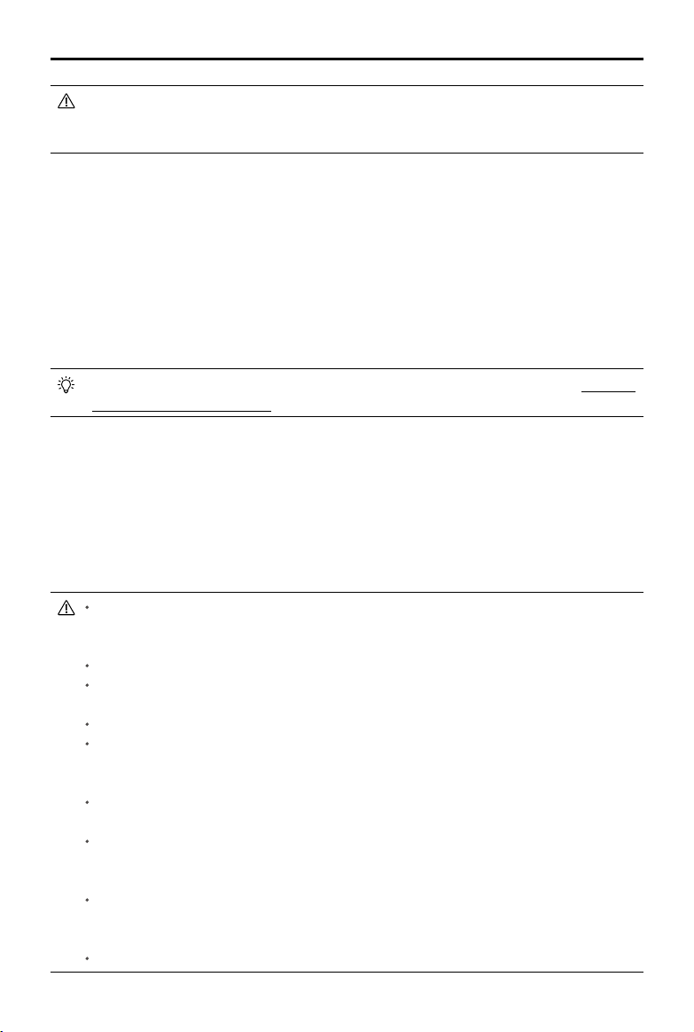
AGRAS MG-1P SERIES User Manual
The horizontal FOV of the radar module is theoretically 50°. The range may fluctuate
between 25° and 50°, however, depending on the size, material, distance, and other factors
of objects.
Obstacle Avoidance Function Usage
There are two scenarios for obstacle avoidance:
1. The aircraft begins to slow down when it detects an obstacle is 15 m away and hovers in place
when 2.5 m away from the obstacle. Users can not accelerate in the direction of the obstacle,
but can y in a direction away from the obstacle.
2. The aircraft immediately brakes and hovers if it detects an obstacle nearby. Users cannot control
the aircraft when it is braking.
When the aircraft is hovering, it is in obstacle avoidance mode. Users can y in a direction away
from the obstacle to exit obstacle avoidance mode and regain full control of the aircraft.
Obstacle avoidance during RTH is different from the above descriptions. Refer to Obstacle
Avoidance During RTH (p. 42) for details.
Altitude Stabilization Function Usage
1. Ensure that you have enabled the altitude stabilization function of the radar module in the DJI
MG app.
2. Congure the desired spraying distance.
3. Enter the desired operation mode. If the operating environment is ideal, the aircraft will y above
the vegetation at the preset height.
In Manual operation mode, users have complete control of the aircraft. Pay attention to
the ying speed and direction when operating. Make sure to be aware of the surrounding
environment and avoid the radar module’s blind spots.
The obstacle avoidance functions are disabled in Attitude mode.
Obstacle avoidance is adversely affected when aircraft pitch exceeds 15°. Please y with
care.
Obstacle avoidance is disabled when ying over surfaces at a height of < 0.8 m.
Aircraft speed should not exceed 5 m/s when flying over surfaces at a height of < 2
m. Aircraft speed should not exceed 7 m/s when flying at a height of ≥ 2 m. Obstacle
avoidance will otherwise be greatly compromised or even disabled.
The radar module enables the aircraft to maintain a xed distance from vegetation only
within its working range. Observe the aircraft’s distance from the vegetation at all times.
Operate with extra caution when flying over inclined surfaces (depending on aircraft
speed). Recommended maximum inclination at different speeds: 10° at 1 m/s, 6° at 3 m/s
and 3° at 5 m/s.
Please maintain full control of the aircraft at all times. DO NOT rely solely on the DJI
MG app. Keep the aircraft within a visual line of sight observing it at all times. Use your
discretion to operate it manually to avoid obstacles.
Comply with local radio transmission laws and regulations.
© 2018 DJI All Rights Reserved.
39
Page 42
AGRAS MG-1P SERIES User Manual
The radar module can only function properly in at landscapes and cannot function in sloping
landscapes with inclinations more than 10° or in landscapes with sudden changes in elevation.
To avoid radar interference, DO NOT use several aircraft within a short distance of each
other.
Before use, ensure that the outer protective cover is not cracked, chipped, sunken, or
misshapen.
DO NOT attempt to disassemble any part of the radar module that has already been
mounted prior to shipping.
The radar module is a precision instrument. DO NOT squeeze, tap or hit.
If the radar module frequently detects obstacles incorrectly, rst check to make sure the
mounting bracket and the aircraft landing gear are properly secured. Second, perform the
IMU calibration. If this still doesn’t work, please contact DJI Support or a DJI Authorized
Dealer.
Keep the protective cover of the radar module clean. Clean the surface with a soft damp
cloth and air dry before using again.
Empty Tank
Prole
An indication appears in the DJI MG app and the aircraft hovers in place when the spray tank
is empty. In Route, A-B Route, and Manual Plus operation modes the aircraft can also be set to
ascend or Return to Home instead of hovering.
Usage
1. When an empty tank warning appears in the app, the sprinklers will automatically turn off.
2. Make sure that the aircraft is in Manual operation mode, land, and then stop the motors. Next,
rell the spray tank and tightly secure the cover.
3. Take off in Manual operation mode and y the aircraft to where the operation was interrupted.
Enter the desired mode to continue the operation.
Return to Home (RTH)
Home Point: The default Home Point is the first location where your aircraft received
strong GNSS signals
The Aircraft Status Indicators will blink several times after the Home Point has been
recorded.
RTH: The Return to Home (RTH) function brings the aircraft back to the last recorded
Home Point.
There are two events that will trigger RTH procedure: Smart RTH and Failsafe RTH.
© 2018 DJI All Rights Reserved.
40
(the white GNSS icon is followed by at least four white bars).
Page 43

AGRAS MG-1P SERIES User Manual
Smart RTH
Press and hold the RTH button on the remote controller when GNSS is available to enable Smart
RTH. Both Smart and Failsafe RTH use the same RTH procedure. With Smart RTH, you may control
the aircraft’s speed and altitude to avoid collisions when returning to the Home Point. The Aircraft
Status Indicators will show the current ight mode during RTH. Press the RTH button once or toggle
the Pause switch to exit Smart RTH and regain control of the aircraft.
Failsafe RTH
Failsafe RTH must be enabled in the DJI MG app. If Failsafe RTH is not enabled, the aircraft
will hover in place when the remote controller signal is lost.
Failsafe RTH activates automatically if the remote controller signal is lost for more than three
seconds, provided that the Home Point has been successfully recorded, the GNSS signal is strong
(white GNSS icon), and the compass is working normally. Users can interrupt the Return to Home
procedure and regain control of the aircraft if the remote controller signal is recovered. Press the
RTH button once or toggle the Pause switch to cancel RTH.
1. Record Home Point (HP)
Blinks green or purple
4. Signal Lost > 3 sec
Blinks yellow
2. Conrm Home Point
Blinks green six times
5. Initiate RTH
Height over HP>15m
Elevate to 15m
15m
Blinks yellow
Height over HP<=15m
3. Remote Controller Signal Lost
Blinks yellow
6. Land After Hovering 5 sec
Blinks yellow
Updating the Home Point
You can update the Home Point in the DJI MG app during ight. There are two options for setting
the Home Point:
1. Set the aircraft’s current coordinates as the Home Point.
2. Set the remote controller’s current coordinates as the Home Point.
Ensure the space above the remote controller’s GNSS module (located beneath the DJI
logo) is not obstructed and that there are no tall buildings around when updating the Home
Point.
Follow the instructions below to update the Home Point:
1. Go to DJI MG > Operation View.
2. Tap
> , select in Home Point settings to set the aircraft’s current coordinates as the
Home Point.
© 2018 DJI All Rights Reserved.
41
Page 44
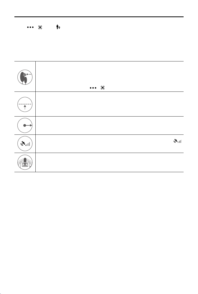
AGRAS MG-1P SERIES User Manual
5 m
H
RTH Altitude
3. Tap > , select in Home Point settings to set the remote controller’s current coordinates
as the Home Point.
4. The Aircraft Status Indicators will blink green to indicate that the new Home Point has
successfully been set.
RTH Safety Notices
The aircraft cannot avoid obstacles during RTH if the operating environment is not
suitable for the radar module. Users can only control the speed and altitude of the
aircraft. If the aircraft is in risk of collision, exit RTH immediately. Before each ight, it
is important to set an RTH altitude that is appropriate for the given environment. Go
> > Set Return to Home Altitude.
5 m
to DJI MG > Operation View >
If the aircraft is ying under 5 meters and RTH (including Smart and Failsafe RTH)
is triggered, the aircraft will rst automatically ascend to 5 meters from the current
altitude. You cannot control the aircraft during this ascent. In Smart RTH, you can
exit RTH to cancel automatic ascent by pressing the RTH button once.
5 m
The aircraft automatically descends and lands if RTH is triggered when the aircraft
H
ies within a 5 m radius of the Home Point.
The aircraft cannot return to the Home Point when GNSS signal is weak (
displays red) or is unavailable.
When the RTH altitude is set to more than 5 m and the aircraft is ascending between
5 m and the preset RTH altitude, the aircraft will stop ascending and immediately
return to the Home Point if you push the throttle stick.
Obstacle Avoidance During RTH
During RTH, if there is an obstacle within 20 m of the aircraft, the aircraft decelerates and then stops
and hovers. While decelerating, if the aircraft comes within 6 m of the obstacle it ies backward to
a distance of around 6 m from the obstacle and hovers. The aircraft then exits the RTH procedure
and waits for pilot commands.
Landing Protection Function
Landing Protection will activate during auto landing.
1. After the aircraft arrives at the Home Point, it will descend to a position three meters above the
ground and hover.
2. Control the pitch and roll sticks to adjust the aircraft position and ensure the ground is suitable
for landing.
3. Pull down the throttle stick or follow the onscreen instructions in the DJI MG app to land the
aircraft.
© 2018 DJI All Rights Reserved.
42
Page 45

AGRAS MG-1P SERIES User Manual
Low Battery Warnings
There are two low battery warnings:
1. Low Battery Warning: The Aircraft Status Indicators slowly blink red. Fly the aircraft back and
land it as soon as possible, stop the motors, and replace the batteries.
2. Critical Battery Warning: the Aircraft Status Indicators rapidly blink red. The aircraft will begin to
descend and land automatically.
Users can set the threshold of both low battery level warnings.
RTK Functions (for MG-1P RTK only)
The MG-1P RTK has a built-in DJI Onboard D-RTK, which provides more accurate data for
centimeter-level positioning to improve agricultural operation when using with DJI D-RTK 2 Mobile
Station. The aircraft’s heading reference from the dual antennas of the onboard D-RTK is more
accurate than a standard compass sensor and can withstand magnetic interference from metal
structures.
Enable/Disable RTK
Ensure that the “RTK Function” is enabled and RTK service type is correctly set (D-RTK 2 Mobile
Station or Network RTK service) before each use. Go to Operation View in the DJI MG app >
RTK to view and set.
Make sure to disable RTK function if not in use. Otherwise, the aircraft will not be able to take off
when there is no differential data.
>
Using with the DJI D-RTK 2 Mobile Station
1. Refer to the D-RTK 2 Mobile Station User Guide to complete linking between the aircraft and the
mobile station and setup of the mobile station.
2. Power on the mobile station and wait for the system to start searching for satellites. The RTK
status icon on top of the Operation View in the DJI MG app will show
has obtained and used the differential data from the mobile station.
to indicate that the aircraft
Using with the Network RTK Service
The Network RTK service uses the remote controller instead of the base station to connect to an
approved Network RTK server for differential data. Keep the remote controller on and connected to
the Internet when using this function.
1. Ensure that the remote controller is connected to the aircraft and has access to the Internet.
2. Go to Operation View in the DJI MG app >
network RTK, and then input the network information.
3. Wait for the remote controller to be connected with the Network RTK server. The RTK status icon
on top of the Operation View in the DJI GS RTK app will show
obtained and used the RTK data from the server.
> RTK, select the RTK service type to custom
to indicate that the aircraft has
© 2018 DJI All Rights Reserved.
43
Page 46

Flight
Operation Environment
1. DO NOT use the aircraft in adverse weather conditions, such as heavy rain (precipitation rate
exceeding 25 mm or 0.98 in within a 12-hour period), high winds exceeding 17 mph (28 kph),
fog, snow, lightning, tornadoes, or hurricanes.
2. Only fly in open areas. Tall buildings and steel structures may affect the accuracy of the
compass and the GNSS signal.
3. Maintain line of sight of the aircraft at all times, and avoid ying near obstacles, crowds, animals,
trees, and bodies of water.
4. Avoid ying in areas with high levels of electromagnetism, including mobile phone base stations
and radio transmission towers.
5. Ensure that there is a strong GNSS signal during operations.
6. DO NOT operate the aircraft indoors.
7. In the Earth's polar regions the aircraft can only operate in Attitude mode.
Flight Limits and No-Fly Zones
Users can set ight limits on height and distance.
Unmanned aerial vehicle (UAV) operators should abide by the regulations from self-regulatory
organizations such as the International Civil Aviation Organization, the Federal Aviation
Administration, and their local aviation authorities. For safety reasons, ight limits are enabled by
default to help users operate this aircraft safely and legally.
When operating with a strong GNSS signal, the height and distance limits and no-y zones work
together to monitor ight. With a weak GNSS signal, only the height limit prevents the aircraft from
going above 30 meters.
Maximum Height and Radius Limits
Users can change the maximum height and radius limits in the DJI MG app. Once complete, your
aircraft will y in a restricted cylinder that is determined by these settings. The tables below show
the details of these limits.
Maximum Flight Altitude
With a strong GNSS signal
Flight Limits
Max Height Flight altitude must be below the preset height.
Max Radius Flight distance must be within the max radius.
© 2018 DJI All Rights Reserved.
44
Max Radius
Home Point
Height of aircraft when powered
on or height of the surface of the
objects below the aircraft
Page 47
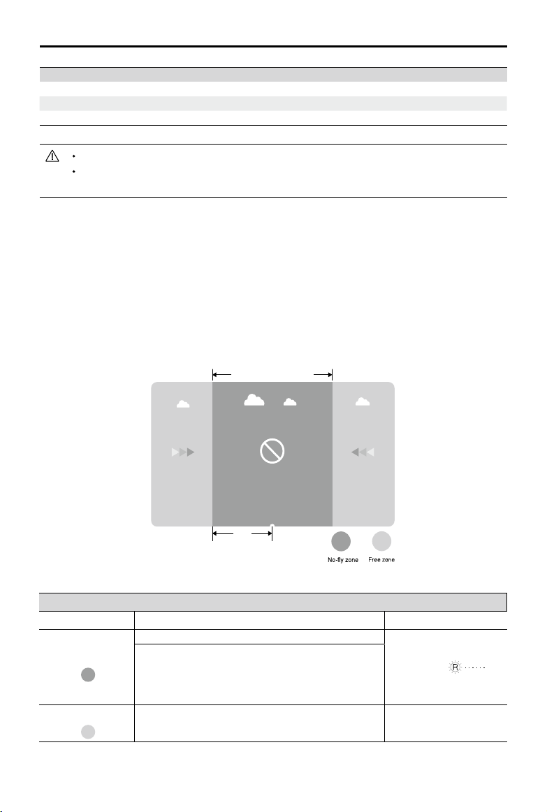
AGRAS MG-1P SERIES User Manual
Restricted Areas
R
With a weak GNSS signal
Flight Limits
Max Height Flight altitude must be below the preset height.
Max Radius No limits.
If you y into a no-y zone, you can still control the aircraft, but cannot y it further.
If the aircraft loses GNSS signal and ies out of the max radius but regains GNSS signal
afterwards, it will y back within range automatically.
No-Fly Zones
Detailed no-fly zones are listed on the DJI official website at http://flysafe.dji.com/no-fly. No-fly
zones are divided into airports and restricted areas. Airports include major airports and ying elds
where manned aircraft operate at low altitudes. Restricted areas include borders between countries
or sensitive sites. The details of the no-y zones are explained below (GNSS required):
R mi around the restricted area (depending on the regulation) is a no-y zone, inside which takeoff
and ight are prohibited.
With a strong GNSS signal
Zone Restriction Aircraft Status Indicators
Motors will not start.
No-Fly Zone
Free Zone
If the aircraft loses GNSS signal and enters the
restricted area but regains GNSS signal afterwards,
the aircraft will enter semi-automatic descent and
land.
No ight restrictions. None.
Blinking Red
© 2018 DJI All Rights Reserved.
45
Page 48

AGRAS MG-1P SERIES User Manual
Semi-Automatic Descent: All stick commands except the throttle stick command are
available during descent and landing. Motors will automatically stop after landing.
When operating in no-fly zones, the Aircraft Status Indicators will blink red slowly and
continue for 5 seconds, then switch to indicate the current ying status and continue for
12 seconds, at which point it will switch back to blinking red slowly.
For safety reasons, DO NOT y near airports, highways, railway stations, railway lines, city
centers, or other busy areas. Ensure the aircraft is visible at all times.
Pre-Flight Checklist
1. The remote controller, aircraft battery is fully charged.
2. The pesticides required are adequate.
3. The position of aircraft battery is secured.
4. All parts are mounted securely.
5. All cables are connected correctly and rmly.
6. Propellers are unfolded and mounted onto the motors securely; frame arms are unfolded and
arm sleeves are rmly tightened.
7. Spraying system is without any blockage.
8. Sprinkler hoses are clear from bubbles. Discharge bubbles, as they may lead to operation
problems. Loosen the valve on the side of the spray nozzle and start the pump. Then tighten the
valve and the sprinkler will work properly.
Calibrating the Compass
Because the aircraft’s compass inside the landing gear leg is highly sensitive, it requires calibration
before your rst ight and regularly to ensure optimal ight performance. Lack of calibration can
lead to abnormal compass data, causing poor ight performance or failure.
DO NOT calibrate your compass where there is a chance of strong magnetic interference,
such as magnetite quarries, parking structures, and underground steel reinforcements.
DO NOT carry ferromagnetic objects such as cellular phones with you during calibration.
DO NOT calibrate near massive metal objects.
DO NOT calibrate in an indoor space.
Calibration Procedures
Choose an open space to carry out the following procedures. It is recommended to calibrate the
compass with an empty tank.
1. Go to the app and tap Perform an Operation to enter Operation View. Tap the Aircraft Status
Bar at the top of the screen and select Calibration in the Aircraft Status List, then follow the onscreen instructions.
2. Hold the aircraft horizontally and rotate it 360 degrees around a vertical axis until the Aircraft
Status Indicators change to solid green and the display goes to the next step in the app.
3. Hold the aircraft vertically, with its nose pointing upward, and rotate it 360 degrees around a
vertical axis.
© 2018 DJI All Rights Reserved.
46
Page 49

AGRAS MG-1P SERIES User Manual
4. The Aircraft Status Indicators show the current ight mode and the calibration page disappears
in the app when calibration is complete. If the Aircraft Status Indicators blink red or a calibration
failure is displayed in the app, repeat the steps above to calibrate the compass.
When to Recalibrate
1. Compass data is abnormal, and the Aircraft Status Indicators are alternately blinking red and
yellow.
2. Flying in a new location, or a location that is different from your last ight.
3. The mechanical structure of the aircraft has changed.
4. Severe drifting occurs in ight (e.g., the aircraft has difculty ying in a straight line).
Calibrating the Spraying System
Be sure to calibrate the spraying system before your rst spray operation, or else it will adversely
affect spraying performance. Use the included measuring cup to ensure accuracy. Calibration
takes around 6 to 14 minutes.
1. Preparation before calibration: If there are any bubbles in the hoses, discharge them before
calibrating. If there are no bubbles proceed directly to calibration.
1
Fill the spray tank with about 2 L of water.
2
Power on the remote controller and the aircraft.
3
Loosen the four manual relief valves on the side of the sprinklers and press the Spray button
on the remote controller until the bubbles in the hoses have been fully discharged.* Tighten
the valves and press the Spray button to stop spraying.
* If the bubbles have still not been fully discharged after a long period of time, rotate the valve cover and
remove it, then re-mount the cover once the bubbles have been fully discharged.
2. Spraying System Calibration
1
Liquid level meter calibration
Pour about 1 L of water into the spray tank. In the DJI MG app go to Operation View >
then tap Calibrate in Flow IMU settings.
Select Nozzle Model, select the correct model in the list (the standard nozzle is model
XR11001VS), then tap Start Calibration. The aircraft will spray automatically, then when ready
the app will indicate that the aircraft is ready for left pump calibration.
© 2018 DJI All Rights Reserved.
> ,
47
Page 50

AGRAS MG-1P SERIES User Manual
2
Left pump calibration
Pour between 1 and 5 L of water into the spray tank, measuring the volume of water precisely
using the measuring cup.
In the app, input the volume of the water your have poured into the tank. Be sure to input
the precise value to avoid calibration bias. Tap Start Calibration and the aircraft will spray
automatically, then when ready the app will indicate that the aircraft is ready for right pump
calibration.
3
Right pump calibration
Repeat the procedure described above for right pump calibration. Once the app indicates
that right pump calibration is complete, wait for a few more moments until the app indicates
that the spraying system calibration procedure is totally complete.
3. Discharge any bubbles in the hoses using the same procedure as used when preparing for
calibration.
During calibration, tap > to cancel. The accuracy of the ow meter will be the data
before calibration.
When to Recalibrate
1. Installing a different nozzle model. Note: choose the corresponding model in the DJI MG app
after replacing nozzles. Go to Operation View >
2. Using a liquid of a different viscosity.
3. The error between the actual value and the theoretical value of the completed area is more than
15%.
> for conguration.
Starting and Stopping the Motors
Starting the Motors
The Combination Stick Command (CSC) listed below is used to start and stop the motors. Ensure
you perform the CSC in one continuous motion. The motors will begin to accelerate to an idle
speed. Release both sticks simultaneously. Take off immediately after the motors are spinning, or
else the aircraft may lose balance, drift, or even takeoff by itself and risk damage or harm.
OR
Stopping the Motors
There are two methods to stop the motors.
1. When the aircraft has landed, push the throttle down and hold. The motors will stop after three
seconds.
Throttle Stick (left stick in Mode 2)
© 2018 DJI All Rights Reserved.
48
Page 51

AGRAS MG-1P SERIES User Manual
2. When the aircraft has landed, push the throttle stick down, then perform the CSC command to
stop the motors. Release both sticks once the motors have stopped.
OR
Throttle Stick
Take off immediately after the motors are spinning, or else the aircraft may drift and cause
damage or harm.
Rotating propellers can be dangerous. DO NOT start the motors in narrow spaces or
when there are people nearby.
Always keep your hands on the remote controller when the motors are spinning.
If you perform the CSC when the aircraft is airborne, the motors will stop and cause the
aircraft to crash. Never stop the motors mid-ight, unless in emergency situations when
doing so can reduce the risk of damage or harm.
It is recommended to stop the motors via method 1. When using method 2 to stop the
motors, the aircraft may tip if it doesn’t touch the ground completely. Please use method 2
with caution.
Flight Test
1. Place the aircraft near the operation area with the Aircraft Status Indicators facing you.
2. Power on the remote controller. Then power on the aircraft.
3. Ensure that the aircraft is connected to the remote controller.
4. When the GNSS signal is strong, perform the CSC command to start the motors.
5. When using with the MG-1P RTK aircraft:
Ensure that the RTK function is enabled and RTK service type is correctly set (D-RTK 2 Mobile
Station or Network RTK service). Go to Operation View in the DJI MG app >
and set.
Make sure to disable RTK function if not in use. Otherwise, the aircraft will not be able to take off
when there is no differential data.
6. Push the throttle stick up to take off.
7. Select the desired operation or ight mode and spray liquid.
8. Exit the operation to manually control the aircraft for landing. Hover over a level surface and
gently pull down on the throttle stick to slowly descend.
9. After landing, push the throttle down and hold. The motors will stop after three seconds.
10. Power off the aircraft, and then power off the remote controller.
> RTK to view
When the Aircraft Status Indicators rapidly blink yellow during flight, the aircraft has
entered Failsafe mode.
The low battery level warning is triggered when the Aircraft Status Indicators slowly blink
red. Fly the aircraft back and land it as soon as possible, stop the motors, and replace
the battery. The critical low battery level warning is triggered when the Aircraft Status
Indicators rapidly blink red. The aircraft will begin to automatically descend and land.
© 2018 DJI All Rights Reserved.
49
Page 52

DJI Assistant 2 for MG
Congure settings of the basic parameters, copy ight records, and update aircraft and remote
controller rmware in the DJI Assistant 2 for MG software.
Installation and Launching
1. Download the DJI Assistant 2 for MG installation le from the MG-1P download page:
http://www.dji.com/mg-1p/info#downloads
2. Install the software.
3. Launch DJI Assistant 2 for MG.
Using DJI Assistant 2 for MG
Connecting the Aircraft
Connect the Micro USB port of the aircraft to your computer with a Micro USB cable. Then power on
the aircraft.
Be sure to remove the propellers before using DJI Assistant 2 for MG.
Firmware Update
A DJI account is required for rmware updates. Login with your DJI account or register for one.
Basic Settings
Congure idle speed of and test the motor.
Tools
Enter SD card mode and copy the ight record.
Connecting the Remote Controller
Connect the USB-C port of the remote controller to your computer with a USB-C cable. Then power
on the remote controller.
Firmware Update
A DJI account is required for rmware updates. Login with your DJI account or register for one.
DO NOT power off the remote controller during the update.
DO NOT perform the rmware update while the aircraft is in the air. Only carry out the
rmware update when the aircraft is on the ground.
The remote controller may become unlinked from the aircraft after the rmware update.
Relink the remote controller and aircraft if necessary.
© 2018 DJI All Rights Reserved.
50
Page 53

Appendix
Specications
Airframe
Diagonal Wheelbase 1500 mm
Frame Arm Length 619 mm
MG-1P:
1460 × 1460 × 578 mm (Frame arms unfolded, propellers removed)
Dimensions
Propulsion System
Motors
Stator Size 60 × 10 mm
KV 130 rpm/V
Max Thrust 5.1 kg/rotor
Max Power 770 W
Weight (With cooling fan) 255 g
ESCs
Max Allowable Current
(Continuous)
Operating Voltage 50.4 V (12S LiPo)
Signal Frequency 30 to 450 Hz
Drive PWM Frequency 12 kHz
Foldable Propellers (21/21R)
Material High-performance engineered plastics
Diameter × Pitch 21 × 7 inch
Weight 58 g
Spraying System
Spray Tank
Volume 10 L
Standard Operating
Payload
Max Battery Size 151 × 195 × 70 mm
Sprinkler Kits
Model XR11001VS
Quantity 4
Max Spray Rate 0.45 L/min (Single nozzle, using water)
Spray Width 4 to 6 m (4 nozzles, 1.5 to 3 m above vegetation)
Droplet Size
High-Precision Radar Module
Model RD2412R
780 × 780 × 578 mm (Frame arms folded)
MG-1P RTK:
1460 × 1460 × 616 mm (Frame arms unfolded, propellers removed)
780 × 780 × 616 mm (Frame arms folded)
25 A
10 kg
XR11001VS: 130 - 250 μm
(Depending on operating environment and spray rate)
© 2018 DJI All Rights Reserved.
51
Page 54

AGRAS MG-1P SERIES User Manual
Operating Frequency
Power Consumption 12 W
EIRP CE / FCC / MIC / KCC: 20 dBm; SRRC: 13 dBm
Field of View (FOV) Horizontal: 50°, Vertical: 10°
Altitude Detection and
Stabilization
Obstacle Avoidance
System
IP Rating IP67
FPV Camera
FOV 123° (H)
Resolution 1280×960 30p
Flight Parameters
Operating Frequency
EIRP
Total Weight (Excluding
battery)
Standard Takeoff Weight MG-1P: 23.8 kg, MG-1P RTK: 23.9 kg
Max Takeoff Weight 24.8 kg (At sea level)
Max Thrust-Weight Ratio 1.71 (Takeoff weight of 23.8 kg)
Hovering Accuracy
(Strong GNSS signal)
GNSS* GPS+GLONASS
Battery DJI approved battery pack (Model: MG-12000P)
Max Power Consumption 6400 W
Hovering Power
Consumption
Hovering Time*
Max Operating Speed 7 m/s
Max Flying Speed 10 m/s (P-mode), 15 m/s (A-mode)
Max Wind Resistance 8 m/s
Max Service Ceiling Above
Sea Level
Operating Temperature 32° to 104° F (0° to 40° C)
*For the Asia-Pacic versionofthe MG-1P RTK, GNSS isGPS+GLONASS+BEIDOU when RTK is enabled.Estimated
hovering time was measured at sea level and in wind speeds under 3 m/s. This value should be used for reference only.
CE / FCC / SRRC (China): 24.00 GHz to 24.25 GHz
MIC (Japan) / KCC (Korea): 24.05 GHz to 24.25 GHz
Detection Range: 1 to 30 m
Stabilization Working Range: 1.5 to 10 m
Sensing Range: 1.5 to 30 m (varies according to the material,
position, shape, and other properties of the obstacle)
Operating Conditions: Flying higher than 1.5 m over the obstacle
with speed lower than 7 m/s
Safety Distance: 2.5 m
Obstacle Avoidance Direction: Forward or backward
2.400 GHz to 2.483 GHz
5.725 GHz to 5.850 GHz (not supported in Japan)
2.4 GHz
FCC: < 26 dBm; CE / MIC / KCC / SRRC: < 20 dBm
5.8 GHz
FCC / SRRC: < 26 dBm; CE / KCC: < 14 dBm
MG-1P: 9.8 kg, MG-1P RTK: 9.9 kg
D-RTK enabled: horizontal ±10 cm, vertical ±10 cm
D-RTK disabled: horizontal ±0.6 m, vertical ±0.3 m (±0.1 m, radar
module enabled)
3800 W (Takeoff weight of 23.8 kg)
20 min (Takeoff weight of 13.8 kg with a 12000 mAh battery)
9 min (Takeoff weight of 23.8 kg with a 12000 mAh battery)
2000 m
© 2018 DJI All Rights Reserved.
52
Page 55

AGRAS MG-1P SERIES User Manual
Remote Controller
Model GL300N
Operating Frequency
Max Transmitting Distance
(unobstructed, free of interference)
EIRP
Display Device
Supported SD Cards microSD. Max Capacity: 128GB
Power Consumption 16 W (typical value)
Operating Temperature 14° to 104° F (-10° to 40° C)
Storage Temperature
Charging Temperature 41° to 104° F (5° to 40° C)
Remote Controller Intelligent Battery
Model WB37-4920mAh-7.6V
Battery Type LiPo battery
Capacity 4920 mAh
Voltage 7.6 V
Energy 37.39 Wh
Charging Temperature 41° to 104° F (5° to 40° C)
Charging Hub
Model WCH2
Input Voltage 17.3 - 26.2 V
Output Voltage and Current 8.7 V, 6 A; 5 V, 2 A
Operating Temperature 41° to 104° F (5° to 40° C)
AC Power Adapter
Model A14-057N1A
Voltage 17.4 V
Rated Power 57 W
2.400 GHz to 2.483 GHz
5.725 GHz to 5.850 GHz (not supported in Japan)
FCC: 3.11 mi (5 km)
CE / MIC / KCC / SRRC: 1.86 mi (3 km)
2.4 GHz
FCC: < 26 dBm; CE / MIC / KCC / SRRC: < 20 dBm
5.8 GHz
FCC / SRRC: < 26 dBm; CE / KCC: < 14 dBm
5.5 inch screen, 1920×1080, 1000 cd/m
4G RAM+16G ROM
Less than 3 months: -4° to 113° F (-20° to 45° C)
More than 3 months: 72° to 82° F (22° to 28° C)
2
, Android system,
© 2018 DJI All Rights Reserved.
53
Page 56

AGRAS MG-1P SERIES User Manual
Aircraft Status Indicators Description
Blinking Patterns Description
×4 Blinking Yellow for 4 times Warming up
Slowly Blinking Yellow A-mode or P-mode (no GNSS)
Slowly Blinking Green P-mode (GNSS)
Rapidly Blinking Green
Solid Red
Rapidly Blinking Yellow Remote controller signal lost
Slowly Blinking Red Low battery level
Rapidly Blinking Red Critical low battery level
Blinking Red, Green and
Yellow
Alternately Blinking Blue
and Green
Alternately Blinking
Red and Yellow
Rapidly Blinking Red
Several Times
Rapidly Blinking Green
Several Times
Self-checking
The aircraft is using RTK data for positioning.
The aircraft brakes and hovers to enter obstacle
avoidance mode when an obstacle is detected.
System error. Restart the aircraft, if still not working,
contact DJI Support or a DJI authorized dealer.
Abnormal compass data, compass calibration
required
Point A recorded
Point B recorded
Updating the Firmware
Users can update the rmware in the DJI Assistant 2 for MG. The DJI MG app can also be used
to update the firmware of both the aircraft and remote controller, if using a firmware version of
01.04.0320 or above. Follow the instructions below.
1. Power on the remote controller and the aircraft. Ensure that the remote controller has access to
the Internet.
2. Connect the USB-C port on the remote controller to the Micro USB port on the aircraft via a
USB-C OTG cable and a Micro USB cable.
3. There will be a prompt on the lower right corner in the DJI MG app if there is new rmware. Tap
the text to enter rmware page.
4. Select the desired rmware and tap Update to enter rmware information page.
5. Tap Download XXX (XXX indicates the rmware version) to download the rmware package for
all the devices.
6. When the download is complete, tap Update XXX under each device to enter the update page
for the corresponding device, then tap Install and wait for the update complete.
7. After successfully completing the update, restart the remote controller and the aircraft manually.
© 2018 DJI All Rights Reserved.
54
Page 57

DJI Support
http://www.dji.com/support
This content is subject to change.
Download the latest version from
http://www.dji.com/mg-1p
If you have any questions about this document, please contact DJI by
sending a message to
AGRAS is a trademark of DJI.
Copyright © 2018 DJI All Rights Reserved.
DocSupport@dji.com
.
 Loading...