


1

Table of Contents
1. INTRODUCTION
1.1. Change of the Aircraft Operation Mode
1.2. Introduction to DJI Dock 2
1.3. Introduction to DJI FlightHub 2
2. REGULATION COMPLIANCE
2.1. USA REGULATIION COMPLIANCE
2.1.1. US Regulatory Framework
2.1.2. BVLOS Waivers
2.1.3. Manufacturer Support
2.2. EU REGULATION COMPLIANCE
2.2.1. EU Regulatory Framework
2.2.2. What is SORA
2.2.3. Manufacturer Support
05
05
06
09
11
12
12
12
13
14
14
15
16
2.3. AUSTRALIA REGULATION COMPLIANCE
2.3.1. Australia Regulatory Framework
2.3.2. BVLOS standard scenarios
2.3.3. Manufacturer Support
3. Site Planning and Deployment
3.1. Site Planning and Survey
3.1.1.Environmental Requirements
3.1.2. Performing Flight Test
3.2. First Use
4. Create a FlightHub 2 Project and Basic Setting
4.1. First Use
4.2. Project Settings
16
16
17
18
19
19
19
20
21
23
23
23
02
2
4.3. Operating Area Management
4.3.1. Custom Flight Area
4.3.2. Obstacle Data
28
28
29

4.4. Aircraft Settings and Remote Debugging
31
5. Automated Flight Workflow
5.1. Route Planning
5.1.1. Area Route Planning
5.1.2. Waypoint Route Planning
5.1.3. Task Planning
5.1.4. Task Execution
6. Manual Flight Workflow
6.1. Pre-flight Check
6.2. One-click Takeoff
6.3. Flight Control
6.4. Situational Awareness
6.5. FlyTo Task
6.6. Gimbal Control
33
33
34
50
60
64
69
69
71
73
74
75
75
6.7. Shooting Settings
6.8. Infrared Settings (Applicable Only to DJI Matrice 3TD Aircraft)
6.9. Manual RTH
6.10. Media File Upload
7. Media File Management
7.1. Photo and Video File Management
7.2. Cloud-Based Modeling
7.3. Model Application
8. Open Ecosystem
8.1. Cloud API
8.2. FlightHub Synchronization
8.3. Edge Computing
76
79
84
84
86
86
89
91
96
96
97
98
8.4. Third-Party Payloads
9. Device Maintenance
99
100
03
3

About DJI Enterprise
Driven by a relentless pursuit of innovation, DJI has revolutionized the way people create
and is now ushering in a new generation of work by helping people understand and adopt
drone technology. Thus, came DJI Enterprise - a global team dedicated to fostering an
ecosystem for businesses to empower individuals, enhance jobs and digitize operations.
In April 2024, DJI launched a new generation of drone-in-a-box solution, DJI Dock
2. DJI Dock 2 is sturdy, reliable, and easy to install, enabling users from Public Safety,
Construction, Energy and other industries to leverage the power of on demand Remote
Drone Operation.
DJI Dock 2 Operation Guidebook
This operation guidebook includes installation and deployment procedures, as well as step-
by-step operation instructions, recommended workflows and parameters for FlightHub
2. By reading this manual, users can quickly grasp the usage methods of the DJI Dock 2,
including mission plan, mission execution, remote manual control, media management,
etc.
4

01
INTRODUCTION
1.1 Change of the Aircraft Operation Mode
In recent years, multi-rotor aircraft have become integral tools across various industries.
As drone technology continues to evolve, the focus of the drone industry has gradually
shifted from data generation and collection to data application. This shift enables large-
scale data application and significantly reduces the costs associated with data collection
and utilization.
However, scaling drone operations presents its own set of challenges. Regular pilot training,
licensing, and the distribution of trained pilots across different work sites can be daunting
tasks. Additionally, in emergencies, users need to transport the aircraft to the site, delaying
timely data collection.
he DJI Dock is DJI's first drone-in-a-box solution, opening up possibilities for automated
and pre-programmed flights that can be conducted and monitored remotely, without the
need for an on-site drone pilot. In March 2024, DJI unveiled the DJI Dock 2, which takes
innovation a step further with a reduced footprint, extended flight time, high-precision
surveying capabilities, and more.
Solutions like the DJI Dock 2 allow users to plan tasks remotely and deliver them to the
dock. Once airborne, the aircraft automatically collects various types of data as configured
in the tasks and uploads the data to the cloud for processing.
The operational mode provided by these solutions differs from that of traditional aircraft.
In scenarios with a fixed flight area or high operation frequency, only a few drone-in-a-box
units need to be deployed to support on-demand task execution and data collection.
05
5

For those interested in the DJI Dock 2, this guidebook serves as a comprehensive tool to
address key considerations for seamless integration, including regulatory compliance,
hardware deployment, software configuration, drone data management, and device
maintenance."
1.2 Introduction to DJI Dock 2
The more capable yet noticeably smaller DJI Dock 2 deploys Matrice 3D or 3TD drones with
ease and security. The DJI Dock 2 lightweight design, offers high-level operation capabilities,
and has cloud-based intelligent functions that bring efficiency and quality to automatic
operations.
The dock can achieve a protection level of IP55 (refer to the IEC 60529 standard). The
longest maintenance interval is six months. The dock comes with a quick-charging module
and an air conditioning system, allowing it to cool down and charge the battery in a short
time. It takes approximately 32 minutes to charge the battery from 20% to 90%.
6

Click here or scan the QR code for more information about DJI Dock 2.
DJI Matrice 3D Series aircraft are equipped with a vision system and infrared sensors to
achieve six-directional obstacle avoidance. Their high-performance multi-camera payload
can meet requirements in various scenarios. The internal RTK module facilitates accurate,
high-precision positioning. The aircraft has a protection level of IP54, suitable for operation
in all weathers.
IP54 50 min Six-directional
Ingress protection rating Max flight time Obstacle avoidance
Positioning accuracy
10 km 400
within ± 3 centimeters
Max operating radius Battery cycle count Integrated RTK module
DJI Matrice 3D Series aircrafts come with two editions: DJI Matrice 3D and DJI Matrice 3TD.
DJI Matrice 3D has a tele camera and a wide-angle camera with a mechanical shutter,
meeting the needs of high-precision mapping tasks.
DJI Matrice 3TD has a wide-angle camera, a tele camera, and an infrared camera and can
display both visible light and thermal images, making it suitable for scenarios such as
security protection and inspection.
07
7

Click here or scan the QR code for specific parameters of DJI Dock 2 and DJI Matrice 3D
Series aircraft.
8
08

1.3 Introduction to DJI FlightHub 2
DJI FlightHub 2 is a cloud-based management platform for DJI Dock 2 and supports flight
task planning, device management, and cloud-based modeling for the dock. Users can
configure flight task plans based on actual needs. The aircraft will automatically take off
according to the preset task plans, and the media files will be automatically uploaded to
DJI FlightHub 2 for cloud-based model reconstruction. During operation, livestreams and
real-time device information can be viewed remotely to monitor the operation site. Users
can also view the operation status of the dock and aircraft and conduct remote debugging,
making device management more convenient.
Function Highlights
Cloud-based Model Reconstruction
DJI FlightHub 2 supports cloud-based model reconstruction. It can generate high-precision
2D and 3D models based on the collected flight data, restoring the operating environment
authentically.
Flight Route Editor
Utilizing high-precision models, users can perform visualized flight route editing from a
first-person perspective and preview simulated imaging results, enhancing the accuracy of
planned flight routes.
AI Spot-Check
Users can drag-select a target area in imaging results, so that the aircraft can automatically
09
9

search for and select the area and adjust the shooting angle of the camera during flights.
This ensures that the aircraft can accurately shoot the same target area during multiple
flights.
FlyTo Tasks
DJI FlightHub 2 provides the FlyTo function to automatically plan the optimal flight route for
aircraft. In case of an emergency task, users can tap a target point and the aircraft will fly to
it along a safe route in an efficient manner.
Remote Control
With DJI FlightHub 2 or a third-party cloud platform, users can still use a keyboard and a
mouse to control the flight behavior and gimbal angle of the aircraft even when the dock is
deployed in a remote area.
Obstacle Bypass
During automated execution of flight tasks, the aircraft is empowered with omnidirectional
obstacle avoidance and automated bypassing to improve the success rate of task
execution.
Click here or scan the QR code for more information about DJI FlightHub 2.
10
010

02
There is a lot of upside potential on integrating drone-in-a-box solutions, however,
leveraging the full power of drone-in-a-box solutions requires navigating through a complex
landscape of roadblocks.
In order to operate the DJI Dock 2 in BVLOS (beyond visual line of sight) scenarios,
operators typically need to obtain special permissions or waivers from the relevant
aviation authorities. These permissions may involve demonstrating the ability to conduct
safe and reliable BVLOS operations, implementing specific safety measures, and utilizing
technologies such as detect-and-avoid systems to mitigate collision risks.
REGULATION COMPLIANCE
Regulatory bodies often require operators to submit detailed operational plans, risk
assessments, and safety protocols for BVLOS operations. Additionally, operators may
need to demonstrate the capability to maintain reliable communication and control of the
drones while operating beyond visual line of sight.
It's important for operators to stay informed about the specific regulations and
requirements related to BVLOS operations in their respective regions, as these regulations
are subject to change and may vary significantly from one jurisdiction to another. Working
closely with aviation authorities and staying abreast of regulatory updates is crucial for
ensuring compliance and safe BVLOS operations with the DJI Dock 2.
In the following sections, we will briefly introduct the current regulatory situation in the US,
EU, and Australia as examples.
11

2.1 USA REGULATIION COMPLIANCE
2.1.1 US Regulatory Framework
Part 107 rules for commercial operations in the US allow visual line of sight operation (VLOS)
only according to 14 CFR §107.31. In order to fly beyond visual line of sight (BVLOS), a drone
operator requires a waiver.
Currently, FAA is in the rulemaking process for the upcoming BVLOS rules that are expected
to streamline operations under 400 ft. In the meantime, the overall waiver process for
authorizing BVLOS operations is not expected to change until this new rules become
effective.
2.1.2 BVLOS Waivers
When a drone operator requests a waiver, a full description is required in order to
substantiate safety of the operation including operational details, UAS details, personnel
details, a risk assessment, and information based on the corresponding FAA guiding
questions for BVLOS operations.
Current BVLOS waivers can vary depending on the characteristics of the operation and
the features of the UAS used. Thus, some type of BVLOS waivers include using Visual
Observer(s), shielding, and use of Detect and Avoid (DAA) equipment.
Visual Observer(s) on site: Option for sites with personnel available (does not require
Part 107 license) to monitor the surrounding airspace, keeping communication with the
remote pilot at all times. Does not require shielding or additional DAA equipment, and
could be up to 400 ft.
Shielding: Low-altitude flights close to (shielded) natural/artificial obstacles or the
ground as the main mitigation to mitigate risk with surrounding air traffic. Typical shielding
12

height is 50 ft over and around obstacles or the ground (standard shielding), and could vary
depending on the specific characteristics of the operational area.
Use of Detect and Avoid (DAA) systems: Drone operators may use DAA systems,
typically ground-based, in order to monitor the surrounding airspace. This would allow for
bigger operational volumes where the drone can fly, nevertheless the additional cost of
these solutions has to be considered as part of the overall deployment.
Information about Part 107 waivers application process here.
Other special waivers are also available for First Responders such as Tactical BVLOS (TBVLOS)
and Special Governmental Interest (SGI).
2.1.3 Manufacturer Support
DJI has obtained FAA approval for BVLOS waivers using VO(s) up to 400 ft and standard
shielding for both DJI Dock and DJI Dock 2. Waiver Safety Explanation documents are
available for drone operators to use them for the preparation of their own waiver
applications.
These waivers apply to the baseline DJI Dock configuration, namely:
Flight Hub 2 + M30 Series Dock version + DJI Dock
Flight Hub 2 + M3D Series + DJI Dock 2
Drone operators can build on top of this technical documentation in order to include
third-party software/equipment as needed by including the corresponding additional
information according to their specific concept of operations.
13

Some characteristics included in the standard shielding waiver are the following:
Nationwide
Remote preflight check –no additional equipment required
Day and night operations
No VO(s), DAA equipment required
Controlled access site on the ground
Supporting Documents such as DJI User Manuals are also included in the technical
documentation package and shall be submitted as part of the operator’s waiver application
within FAADroneZone.
Please contact DJI authorized dealers for more information regarding the technical
documentation available for supporting your BVLOS waiver application.
2.2 EU REGULATION COMPLIANCE
2.2.1 EU Regulatory Framework
The European Union Aviation Safety Agency (EASA) establishes comprehensive regulations
for the safe, secure, and environmentally responsible operation of civil drones within the
EU.
According to EASA Regulations (EU) 2019/947 and 2019/945, the DJI Dock 2, as an
automated drone solution with remote pilot control, typically falls under the Beyond Visual
Line of Sight (BVLOS) operations in the "specific category"
To operate in the specific category, drone operators must obtain an operational
authorization from the National Aviation Authority (NAA) of the state of registration before
start the flights. There are 4 ways to obtain the authorization:
14

Submit a declaration based on a Standard Scenario (STS)
Obtain an operational authorization following a Pre-Defined Risk Assessment (PDRA)
Obtain an operational authorization following the Specific Operations Risk
Assessment (SORA) procedure
Acquire a Light UAS Operator Certificate (LUC)
2.2.2 What is SORA
The SORA (Risk assessment of the intended operation) is the risk assessment methodology,
when conducting an operation not covered by a STS or a PDRA, applicants are required to
conduct a risk assessment, identify mitigations and comply with safety objectives.
EASA published the SORA as an Acceptable mean of compliance to Article 11 to Regulation
(EU) 2019/947.
Start to apply for authorization from here
Find additional information about SORA here
learn more about specific category here
Operations Manual example for UAS operations at SAIL II provided by EASA
15

2.2.3 Manufacturer Support
DJI, as the manufacturer, provides product-related documentation to assist end-users in
preparing the SORA and Concept of Operations (ConOps), including:
DJI Dock 2 Matrice 3D Series Unmanned Aircraft Flight Manual
DJI Dock 2 Quick Installation Guide
DJI Flight Hub 2 - User Manual
Opertaions Manual and Requirement Document
DJI Matrice 3D Series DJI Dock 2 Maintenance Manual
DJI Dock 2 Robustness report
SORA-UAS Operations Over A XXX Area
DJI’s Manufacturer Declaration
Please contact DJI authorized dealers for more information regarding the technical
documentation for supporting your application.
2.3 AUSTRALIA REGULATION COMPLIANCE
2.3.1 Australia Regulatory Framework
The Civil Aviation Safety Authority (CASA) is Australia’s regulatory body for civil aviation
safety. CASA's main role is to regulate and oversee aviation safety in Australia, ensuring
that both national and international aviation operations meet stringent safety standards.
BVLOS (Beyond Visual Line of Sight) refers to a mode of operation where drones are flown
beyond the visual range of the operator. Traditional drone operations typically require
the operator to maintain visual contact with the drone to ensure safe operation. However,
BVLOS operations break this limitation, enabling drones to perform tasks over greater
distances and in more complex environments. This is crucial for operating DJI Dock2. Below
are the conditions required for executing BVLOS operations:
16

To fly beyond visual line-of-sight (BVLOS), you must have:
remotely piloted aircraft operator's certificate (ReOC)
remote pilot licence (RePL) with either:
a pass in the Instrument Rating or BVLOS exam
operate under the direct supervision of an individual who holds a pass in one of the
exams (refer CASA EX27/23)
BVLOS flight authorisation.
To apply for a BVLOS flight authorisation, the chief remote pilot must:
fill out Application for RPA flight authorisation (area approval / permission) form 101-
09
include supporting documents based on the SORA or a BVLOS standard scenario
pay the estimated fee following review of your application, additional fees may apply
if an RPAS Inspector must travel to complete the assessment
complete an operational check (if this is your first BVLOS application).
Australia's Civil Aviation Safety Authority (CASA) also adopts the Specific Operations Risk
Assessment (SORA) as a compliance standard.
2.3.2 BVLOS standard scenarios:
CASA has developed a suite of standard scenarios that you can use to apply for BVLOS
operations with common characteristics.
For more information, please refer to the CASA official website:
https://www.casa.gov.au/drones/registration-and-flight-authorisations/apply-flight-
authorisations/apply-beyond-visual-line-sight-approvals#Therequirements
17

2.3.3 Manufacturer Support
DJI, as the manufacturer, provides product-related documentation to assist end-users in
preparing the SORA and Concept of Operations (ConOps), including:
DJI Dock 2 user manual
DJI Dock 2 maintenance manual
DJI M3D Series –DJI Dock 2 BVLOS Operations: Safety Explanation
DJI Dock 2 robustness report
M3D M3TD series Dock 2 bundle Manufacturer Declaration
Please contact DJI authorized dealers for more information regarding the technical
documentation for supporting your application.
18

03
Site Planning and Deployment
3.1 Site Planning and Survey
Once we have reviewed and complied with the regulations, it's time to select the location to
deploy our dock. The selection of a site requires consideration of multiple factors, including
environmental, electrical and network factors. In the following section we provide the
standard site selection and installation requirements to ensure the functional capabilities
of the DJI Dock 2.
Failure to select a site according to the requirements may lead to the malfunctioning of
the dock, operational stability deterioration, shortening of the service life, unsatisfactory
effects, potential safety hazards, property losses, and casualties.
3.1.1 Environmental Requirements
The installation site altitude should not be higher than 4000 m. ·
The annual temperature of the installation site should be between -25°to 45°C(-13° to
113° F), considering the dock operating temperature is between -25°to 45°C(-13° to 113° F),
and the aircraft flight operating temperature in the dock is between -20° to 45°C(-4°to113°
F).
Make sure there are no obvious biological destructive factors such as rodent
infestation and termites at the installation site.
DO NOT install the dock near dangerous sources without permission, such as gas
stations, oil depots, and dangerous chemical warehouses.
DO NOT install the dock in a site with flammable materials such as debris and catkins
that are easy to accumulate.
DO NOT install the dock on moving objects, such as cars and boats. Avoid installing
the dock in lightning strike areas.
19

Avoid areas that are prone to water accumulation, severe erosion, landslides, heavy
snow accumulation, or other natural disasters.
Avoid installing the dock in areas with chemical plants or septic tanks upwind to
prevent pollution and corrosion. If the dock is configured near coastlines, avoid installing in
areas where the dock may be immersed in or splashed by seawater in order to prevent the
corrosion of metal components.
3.1.2 Performing Flight Test
When carrying out a dock project, one often encounters the problem of how many
docks are needed to cover the customer's operating area. This requires consideration of
factors such as maximum image transmission distance, number of tasks, and maximum
endurance. It is recommended to conduct a flight test at the planned site to evaluate the
operational capabilities.
Flight testing requires testing in multiple directions in order to understand the actual
operating range of an dock.
20

3.2 DJI Dock 2 Installation and Deployment
Construction and installation diagram:
The installation of DJI Dock 2 consists of the following steps:
1
Check the environment: Check the installation site and make sure it meets the
environmental requirements of DJI Dock 2. For example, there should be stable mains
supply and network conditions, no surrounding obstructions, and a strong satellite signal.
2
Complete electrical and network connection: Connect the dock to a stable 1,000
W mains supply. Make sure the dock can connect to the Internet with an upstream and
downstream bandwidth greater than 10 Mbps. The power cable and the Ethernet cable
must be laid with PVC pipes and installed under the ground. For scenarios in which PVC
pipes cannot be installed under the ground, use galvanized steel pipes fastened to the
ground.
21

3
Connect the dock to the ground: The dock needs to be connected to the ground to
discharge the lightning current to the earth. Make sure that the earthing resistance for the
dock is less than 10 Ω.
4
Complete base construction: Fix DJI Dock 2 on a base to raise the height of the dock,
avoiding the risk of water immersion. Use a concrete base or a steel frame base.
5
Install a protective fence: It is recommended to install a protective fence so that
unauthorized personnel cannot enter the area where the dock is installed.
6
Install a third-party security camera: An additional third-party security camera can be
installed according to security monitoring requirements.
Note: The installation, debugging, maintenance, troubleshooting, and repair of
DJI Dock 2 must be performed by DJI authorized technicians in compliance with local
regulations.
Refer to the DJI Dock 2 Installation and Setup Manual for more details about installation
and deployment.
22

04
Create a FlightHub 2 Project
and Basic Setting
After the installation and set up process has been completed, you can proceed to bind
the DJI Dock 2 to a DJI FlightHub 2 account. FlightHub 2 is an all-in-one cloud-based drone
operations management platform that helps you achieve comprehensive, real-time
situational awareness. to If you don't have a DJI FlightHub 2 account yet, you can register
using the link below: https://fh.dji.com/login
4.1 First Use
The first time you use DJI Dock 2, you need to create a FlightHub2 organization and project,
then bind the dock to the corresponding project in DJI FlightHub 2. For details, watch the
tutorial video DJI Dock 2 | First Use.
4.2 Project Settings
After creating an organization and a project, click the icon in the bottom-left corner of the
home screen. On the project settings page, complete the basic settings for the project.
23

Enter a name and description for the project.
24

Click Set POI to set the coordinates of the point of interest for the project. The set point will
be displayed in the middle of the web page when users enter the project, allowing users to
quickly locate the project area.
After creating a project, administrators can enable Join Project with Code. Then, they can
copy the project ID and code as well as the project link and send them to members who
want to join the project.
DJI Dock 2 allows you to enable Weather-Related Flight Restriction. We recommend that
you enable both Weather-Related Restriction on Cloud and Include Weather Forecast. After
the two functions are enabled, the aircraft will combine data from the integrated weather
station of the dock with online weather forecasts to determine whether to restrict flights,
and therefore to ensure safety.
25

Administrators can enable livestream and media file sharing in Sharing Settings, and then
send QR codes and links to members who want to view the livestreams and media files of
the aircraft.
26

Administrators can add project members or adjust the roles of members. To view the
permissions granted to each role, move the pointer over the exclamation mark next to the
column name Role.
27

4.3 Operating Area Management
4.3.1 Custom Flight Area
If your flight areas are subject to certain restrictions, you can set custom flight areas. Click
the Map Task Area icon.
28

Click in the top-right corner to create a custom flight area. Custom flight areas are
classified into the following types:
GEO Zone (red): The aircraft cannot enter the GEO Zone or take off when it is inside the
GEO Zone.
Task Area (green): The aircraft can perform tasks within the area and cannot take off when
it is outside the area.
Note: If the distance between the aircraft and the boundary of the custom flight
area is less than 5 meters during a task, the task will be interrupted and the aircraft will
return home directly. Pay attention to the distance between the flight route and the
boundary of the custom flight area when planning a task.
4.3.2 Obstacle Data
DJI Dock 2 allows you to import 3D models to set obstacle data, improving flight safety for
aircraft. Based on the obstacle data, the aircraft can automatically plan an optimal flight
29

route to bypass obstacles along the flight route and ensure safe and quick arrival when
performing FlyTo tasks or returning home.
30

4.4 Aircraft Settings and Remote Debugging
After completing project and operating area settings, you still need to configure aircraft
settings. Click Actions to go to the settings page. The settings include Beacons, Alternate
Route Altitude, Max Flight Altitude, Max Flight Distance, Obstacle Sensing, Charging Mode,
and Photo Transfer. Configure the settings based on your actual needs.
Charging Mode can be set to Schedule or Standby. The Schedule mode is suitable for
performing regular tasks. The battery will be charged to a level between 55% and 60%
when no task is distributed. The Standby mode is suitable for performing urgent tasks.
The battery will be charged to a level between 90% and 95% when no task is distributed
but the battery life will be shorter. We recommend that you select Schedule unless for
emergencies.
31

Take note that aircraft settings can be modified only when Aircraft Status is set to On in the
Remote Debugging window. After Remote Debugging is enabled, you can remotely restart
the dock and aircraft.
32

05
DJI Dock 2 supports two flight modes: live flight controls and automated flight. This chapter
describes the automated flight mode first.
The automated flight workflow is as follows:
Flight route planning -> plan settings -> task execution -> media file upload.
Automated Flight Workflow
5.1 Route Planning
DJI Dock 2 supports two route planning modes: Waypoint Route and Area Route. The
Waypoint Route mode is mainly used to plan patrolling and inspection tasks and the Area
Route mode is mainly used to plan mapping tasks.
33

5.1.1 Area Route Planning
5.1.1.1 Mapping Area Planning
The first step of mapping is to select an operating area. Currently, two methods are
available for mapping area planning.
1
Manually draw a mapping area in DJI FlightHub 2
In the flight route library, click "+" in the top-right corner of the flight route list. Set Route
Type to Area Route, select a model and the aircraft you want to use, and then click OK.
Click on the map to set a reference takeoff point. In most cases, it is recommended to set
the dock location as the reference takeoff point.
34

Click on the map to draw a mapping area.
35

2
Create a mapping area by importing a KML file
On the Map Annotations page, click the import icon. Select the WGS84 coordinate system
and the altitude mode that is selected for creating the KML file to be imported. Disable Set
Evaluation Value and Downsampling and upload the KML file.
After the file is imported, right-click to convert the KML file to a mapping area.
36

5.1.1.2 Route Parameter Settings
After setting the mapping area, configure the route parameters.
1
Collection Method
Select a collection method based on your actual needs. For 2D model reconstruction, select
Ortho Collection. For high-quality 3D model reconstruction, select Oblique Collection. If
quality requirements for 3D models are not high or no buildings or large altitude difference
exists in the mapping area, you can also select the Ortho Collection mode to collect data
more efficiently for 3D model reconstruction.
37

If you select Oblique Collection, we recommend that you enable Smart Oblique (supported
for DJI Matrice 3D aircraft but not for DJI Matrice 3TD aircraft) to improve collection
efficiency.
After you enable Smart Oblique, the aircraft will fly along two mutually perpendicular
s-shaped flight routes to photograph the mapping area from different angles in sequence.
2
GSD Settings
Ground Sample Distance (GSD) is the physical distance between two adjacent pixels on
the ground. Adjusting the GSD value will affect parameters such as the flight altitude.
The relationship between GSD and flight altitude is as follows: GSD ≈ Flight Altitude/37
(applicable to DJI Matrice 3D aircraft). Set a GSD value based on your actual requirements
for the model accuracy. (Use double GSD to estimate the model accuracy. For example, if
the GSD value is set to 5 cm/pixel, the model accuracy is approximately 10 cm. Take note
that model accuracy is affected by many factors in actual scenarios and this formula is used
only for rough estimation.)
If you select Oblique Collection, the Oblique GSD parameter is displayed, which indicates
the GSD of a photo shot at a swing angle. Formula: Oblique GSD = GSD/cos (Swing angle of
the gimbal). For example, if the swing angle of the gimbal is 45°, the oblique GSD is GSD/
cos45° ≈ GSD × 1.414.
38

The swing angle of the gimbal is the tilt angle of the gimbal during collection in Oblique
Collection mode, which can range from 10° to 45°. Different from the traditional tilt
angle whose value 90° indicates vertically downward, the swing angle 0° means vertically
downward and 90° indicates horizontally forward. Theoretically, the higher the flight
altitude or the flatter the ground (without tall buildings) is, the smaller the tilt angle should
be set (close to 10°). The lower the flight altitude is, the larger the tilt angle should be set
(close to 45°). In most cases, it is recommended to set the tilt angle to 45°.
3
Safe Takeoff Altitude
After takeoff, the aircraft will first ascend vertically to the safe takeoff altitude and then
fly along the selected flight route. In most cases, a safe takeoff altitude of 20 meters is
sufficient. If there is a tall building near the installation site of DJI Dock 2, it is recommended
to set the takeoff altitude to be at least 20 meters higher than the tall building.
39

If the safe takeoff altitude is higher than the altitude of the first waypoint, the aircraft will
fly to the first waypoint at the safe takeoff altitude. If the safe takeoff altitude is lower than
the altitude of the first waypoint, the aircraft will ascend vertically to the altitude of the first
waypoint and then fly to the first waypoint.
Safe takeoff altitude higher than the altitude of the first waypoint
Safe takeoff altitude lower than the altitude of the first waypoint
4
Altitude Mode
DJI Dock 2 supports three altitude modes.
40

Absolute Altitude: Set a flight altitude relative to the sea level. The aircraft will fly
consistently at this altitude.
Relative to Takeoff Point: Set a flight altitude relative to the takeoff point. The aircraft will fly
consistently at this altitude. We recommend that you select Relative to Takeoff Point if the
mapping area is flat.
Above Ground Level (for terrain following): Set a flight altitude relative to the ground
below the aircraft. The aircraft will adjust its flight altitude based on the undulations on
the ground, ensuring a consistent altitude relative to the ground. We recommend that
you select Above Ground Level to improve model quality if the mapping area has large
undulations, such as limestone pits or mountainous areas.
41

In Above Ground Level mode, the aircraft adjusts its flight altitude to follow the terrain.
In Absolute Altitude or Relative to Takeoff Point mode, the aircraft maintains a consistent
flight altitude.
42

After you select an altitude mode, we recommend that you change the flight altitude
by adjusting the GSD setting. When the GSD value changes, the flight altitude changes
accordingly based on the formula: GSD ≈ Flight Altitude/37 (applicable to DJI Matrice 3D
aircraft).
5
Terrain Follow File Management
If you select the Above Ground Level altitude mode, you need to import an elevation model
of the mapping area to generate a flight route with altitude changes.
Elevation models can come from three sources:
Built-in global elevation data of DJI FlightHub 2: DJI FlightHub 2 provides built-in
elevation data ready for use. The error range of the elevation data is 10 to 30 meters.
Import of an existing elevation model: In the model library, click Import, upload an
elevation model file, and then select the Display Model on Map once Imported. To upload
an elevation data file generated by DJI Terra, upload the dsm.tif or gsddsm.tif file (gsddsm.
tif is a downsampling file with a low resolution).
43

Click Import in the model library
Upload an elevation model file
After uploading the file, go to the Map Models page, select the uploaded elevation model
file, and then click the Load elevation data icon.
Cloud-based model reconstruction in DJI FlightHub 2 (recommended): After a flight
task along an area route is complete, you can use DJI FlightHub 2 to perform cloud-based
44

model reconstruction, during which cloud computing power is utilized to generate a base
map of the mapping area. Then, you can click the load icon in the map view to load the
elevation data of the model. The model generated this way is based on the latest data, and
therefore is more accurate than the built-in global elevation model. This model generation
method is recommended for terrain following to improve flight safety.
Generally, the loaded elevation data is more accurate than the built-in global elevation
model. Therefore, the loaded elevation data instead of the built-in global elevation data is
used for terrain following. Outside the coverage of the loaded elevation model, the global
45

elevation data is used.
If multiple base maps with different elevation data are loaded at the same time and the
base maps overlap, the highest altitudes in the overlapping area are used to design the
terrain follow route to ensure flight safety.
6
Global Flight Speed
If you use DJI Matrice 3D, we recommend that you set Global Flight Speed to the maximum
allowed flight speed to improve task execution efficiency. In normal cases, the maximum
allowed flight speed is 15 m/s. However, when the flight altitude is low (flight altitude lower
than 50 meters and forward overlap ratio of 80%), the maximum allowed flight speed is
lower than 15 m/s.
Matrice 3TD aircraft is not equipped with mechanical shutters and too fast a speed may
cause motion blur. If you use such aircraft, we recommend that you reduce the flight speed
to an appropriate value.
7
Course Angle
After the mapping area is set, a course angle is automatically calculated for optimal flight
efficiency. We recommend that you use this course angle.
46

8
Elevation Optimization
When enabled, the aircraft will fly to the center of the mapping area and capture a series
of tilt-angle photos after it finishes its flight task. The tilt-angle photos can help improve the
accuracy of elevation data in the final model. We recommend that you enable this function.
9
Advanced Settings
In Advanced Settings, you can set the Side Overlap Rate/Forward Overlap Rate, Margin,
Photo Mode, Custom Camera Angle, Route Start Point, and Bypass Obstacle parameters. In
most scenarios, you are advised to use the default advanced settings.
(1) Side Overlap Rate/Forward Overlap Rate: The default value of Side Overlap Rate is 70%,
and the default value of Forward Overlap Rate is 80%.
The side overlap rate 70% ensures both efficiency and accuracy and is suitable for most
scenarios. If the altitude mode is set to Above Ground Level or the mapping area is flat (an
area is deemed flat if its biggest altitude difference is smaller than 10% of the flight altitude,
47

for example, an area with a flight altitude of 100 meters and a biggest altitude difference
of less than 10 meters), you can decrease the side overlap rate to 60% to improve task
execution efficiency. We recommend that you do not set the side overlap rate to a value
less than 60%. If the side overlap rate is less than 60%, accuracy may be impaired. If the
side overlap rate is less than 50%, the orthomap may be incomplete.
In most cases, we recommend that you use the default forward overlap rate of 80%. If you
want to accelerate model reconstruction, you can reduce the forward overlap rate to an
appropriate value so that the aircraft will shoot fewer photos. However, setting a forward
overlap rate lower than 70% is not recommended.
(2) Margin
Margin specifies the distance to which the flight route can extend outside the mapping
area. The margin is 0 meters by default and can be set to 100 meters at most. In projects
for which high output quality is required, the flight route must extend outside the mapping
area to an appropriate extent to ensure the accuracy and quality of data collected within
the mapping area. In such scenarios, set a margin based on your actual needs.
48

(3) Photo Mode
Timed Interval Shot is used by default. In this mode, the aircraft can automatically adjust
the shooting interval based on the resolution, flight speed, and forward overlap rate. You
can change the shooting interval based on your needs. The shortest shooting interval is 0.7
seconds.
(4) Custom Camera Angle
This setting is disabled by default. After it is enabled, you can adjust the camera angle
during flights. Take note that this function may change the coverage of the shooting
area. This function needs to be enabled only in rare scenarios. For example, to inspect
photovoltaic panels, you can enable this function to allow change of the yaw angle and
camera angle so that the camera remains perpendicular to the photovoltaic panels during
shooting.
49

(5) Route Start Point
Any of the four vertices of the flight route can be set as the route start point. These vertices
are generated by the system to ensure optimal flight efficiency. The default start point of
the flight route is the vertex closest to the takeoff point. We recommend that you use the
default start point.
(6) Bypass Obstacle
If Bypass Obstacle is enabled, the aircraft will try to bypass obstacles along the flight
route. If the bypass fails, the flight task will be interrupted. Obstacle bypass may result in
unexpected mapping results. This function is disabled by default. We recommend that you
do not enable it.
5.1.2 Waypoint Route Planning
1
Create a flight route.
Click the flight route library icon in the left-side menu. In the flight route library, click "+"
in the top-right corner of the flight route list. Set Route Type to Waypoint Route, select an
aircraft model (Matrice 3D or Matrice 3TD), and then set a route name.
2
Set a reference takeoff point.
Click the dock icon on the map to set the dock as a reference takeoff point.
50

3
Set a safe takeoff altitude.
We recommend that you select Direct Ascent and set the safe takeoff altitude to be over 20
meters higher than nearby obstacles.
4
Select an altitude mode.
In most cases, we recommend that you select the ALT or AGL altitude mode and set a flight
altitude based on your actual needs.
5
Set a global flight speed.
The global flight speed is the maximum flight speed for aircraft. Set a speed based on your
actual needs. If you want your aircraft to take photos only at waypoints but not along the
route between two waypoints (for example, during a patrolling task, the aircraft needs to
take photos only at key points), we recommend that you set the speed to 15 m/s to improve
51

task execution efficiency.
If you want your aircraft to take photos all along the patrolling flight route, for example, at
timed intervals, too fast a speed may cause motion blur and affect the quality of photos
(especially for DJI Matrice 3TD aircraft, which are not equipped with mechanical shutters).
To improve photo quality, we recommend that you set the flight speed to 10 m/s and then
make adjustments according to the quality of the photos taken.
6
Configure advanced settings.
In most cases, we recommend that you use the default advanced settings.
7
Edit the flight route.
(a) If you are planning an inspection flight route, we recommend that you use the new flight
route editor, which utilizes high-precision 3D models and allows you to perform visualized
flight route editing from a first-person perspective. For details, refer to the tutorial videos:
DJI FlightHub 2: Waypoint Mission Planning Essentials:
https://www.youtube.com/watch?v=_sIK7QoEKT4
DJI FlightHub 2: Utilizing 3D Models for Flight Planning:
https://www.youtube.com/watch?v=3z1hU0863bg
52

(b) If you are planning a patrolling flight route, which usually does not have a specific
inspection target or has a moving inspection target, we recommend that you click the
waypoint adding icon in the top-right corner of the map view and then click on the map to
quickly add waypoints to generate a patrolling flight route based on your actual needs.
53

After editing the flight route, perform a safety check to ensure that a safe distance is kept
between the flight route and the surrounding obstacles.
54

8
Set a gimbal tilt angle.
After you plan a patrolling flight route, you need to set a gimbal tilt angle. At the first
waypoint, click More and select Gimbal Tilt. The camera view in the bottom-right corner,
coupled with the imported base map model, provides an immersive operation experience
and allows you to quickly set an appropriate gimbal tilt angle.
After you set a gimbal tilt angle at the first waypoint, the gimbal title angles at the following
waypoints change accordingly.
55

9
Set an aircraft yaw angle.
By default, the shooting angle of the aircraft is consistent with the flight route direction. If
you want to adjust the shooting angle (for example, your aircraft is expected to fly along a
river and take photos of the banks of the river), you need to adjust the aircraft's yaw mode
first.
In the advanced settings of the flight route, the aircraft yaw mode is set to Along Route by
default. Change the mode to Manual.
At the first waypoint, click More and select Aircraft Yaw. In the camera view in the bottom-
right corner, set an appropriate yaw angle.
After you set an aircraft yaw angle at the first waypoint, the yaw angles at the following
waypoints change accordingly. We recommend that you check each waypoint in the
bottom-right camera view to ensure that the yaw angles are correct. To adjust the yaw
angle at a waypoint, repeat the previous operations.
56

10
Set waypoint actions.
If you want your aircraft to take photos all along the flight route, at the first waypoint, click
57
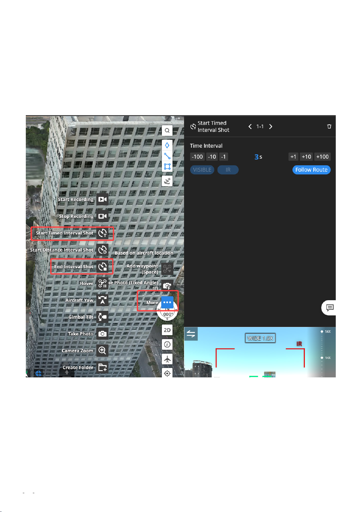
More, select Start Timed Interval Shot, and then set an interval. At the last waypoint, click
More and select End Interval Shot. Your aircraft will automatically shoot photos at the
specified interval throughout the entire flight task. If you want your aircraft to take photos
only at waypoints, press F on the keyboard to create shooting actions at the corresponding
waypoints.
If you want your aircraft to record videos, we recommend that you configure it to record
videos only for flight route segments between key waypoints. Recording a video of the
entire flight route is not recommended, because the video will be excessively large and
take a long time to upload. To record a video of a flight route segment between two key
waypoints, select Start Recording at one key waypoint and Stop Recording at another.
58

59

During security patrolling flights, hovering is sometimes required for inspection. In this
case, you can add the Hover action at the corresponding waypoints. The hovering duration
can be set to 1 to 1,800 seconds.
5.1.3 Task Planning
After flight route planning, you can create a task plan in the task plan library.
60

1
Basic Settings
Create a task plan, enter a plan name, and select a flight route and a device.
2
Positioning Accuracy
DJI Dock 2 supports two positioning modes: high-precision RTK and GNSS.
61

High-precision RTK: After takeoff, the aircraft will wait in the air until RTK data is converged
before performing the flight task. This mode is recommended for mapping or detailed
inspection tasks that require high accuracy.
GNSS: The aircraft does not need to wait for RTK data convergence and can directly start
performing the flight task after takeoff, with a shorter time of preparation. This mode is
recommended for patrolling tasks with lower accuracy requirements.
30
Plan Timer
You can select Immediate, Timed, Recurring, or Continuous based on your actual needs. For
tasks with periodic model updates, select Recurring and set the date, time, and frequency
for task execution.
62

4
Optimal RTH Route Planning
If you enable this function, the aircraft will adjust the flight altitude (not the set RTH
altitude) automatically to suit environmental factors such as the wind speed, wind direction,
and obstacles when returning home.
If the lighting is sufficient and the environment is suitable for the vision system to work
properly or Obstacle Data is enabled, the aircraft will automatically plan an optimal flight
route to improve task efficiency and preserve battery life.
If the lighting is insufficient and the environment is not suitable for the vision system to
work properly and Obstacle Data is disabled, the aircraft will fly based on the flight altitude
and RTH altitude settings.
If this function is enabled, the aircraft will not fly strictly at the RTH altitude when returning
home. If there are small obstacles surrounding the mapping area such as power lines,
there will be safety risks. We recommend that you do not enable this function.
5
RTH Altitude
Set an RTH altitude based on the actual conditions in the mapping area. The RTH altitude
must be at least 20 meters higher than the highest obstacle on the RTH path to ensure safe
RTH.
63

6
Signal Lost During Flight
Set the action that you want the aircraft to perform if the image transmission signal is lost
during a flight. For example, the image transmission signal may be blocked and lost after
the aircraft flies over mountains. We recommend that you select Return to Home to ensure
flight safety and data quality. As the RTK link is embedded in the image transmission link,
the RTK signal will also be lost after the image transmission signal is lost. If you select
Continue Task, the positioning mode of the aircraft will be switched to GNSS, and the
accuracy of the output data cannot be ensured.
7
Resume Flight from Breakpoint
When this function is enabled, a breakpoint will be recorded if the aircraft cannot complete
a flight task due to a low battery. After being charged to a sufficient battery level, the
aircraft will automatically resume the task from the breakpoint until the flight task is
complete. This function is disabled by default. If the flight route of a flight task is long and
the aircraft cannot complete the task in one flight, we recommend that you enable this
function.
5.1.4 Task Execution
5.1.4.1 Pre-flight Check
Before you start a new flight task, we recommend that you double-check the parameter
settings such as the altitude mode and flight altitude on the task details page and then go
to the console and check the parameter settings such as the maximum altitude, maximum
distance, obstacle avoidance setting, and operation mode.
64

After parameter check, we recommend that you use the Live Flight Controls function of
DJI Dock 2 to manually fly the aircraft along the boundary of the mapping area, with the
gimbal pointing forward. As you fly the aircraft, look around to make sure there is no risk of
collision. Then, you can start the flight task.
5.1.4.2 Task Monitoring
During the flight task, the console displays in real time the status of DJI Dock 2 and the
aircraft as well as information such as alerts, meteorological information (wind speed,
rainfall, and temperature), and flight information (battery level, searched satellites, flight
altitude, and flight speed).
65

During the flight task, you can monitor the aircraft in real time. You can check the live
camera view of the aircraft and the real-time location of the aircraft is displayed on the
map.
In special circumstances (for example, the aircraft needs to bypass obstacles in an
emergency), you can click Aircraft Control in the control window to manually take over
control of the aircraft.
66

5.1.4.3 Media File Upload
After completing the task and returning to the dock, the aircraft automatically uploads
the photos and videos shot during the flight to DJI FlightHub 2, where the media files will
be categorized and archived based on task execution time. You can view and manage
the media data on the cloud or download the data to your local device for viewing and
management.
67

68

06
The manual flight workflow is as follows:
pre-flight check -> one-click takeoff -> manual control of the aircraft -> RTH -> data upload.
Manual Flight Workflow
6.1 Pre-flight Check
1
Obtain control of the device.
Go to the Online Devices panel and check the battery level and health status of the aircraft
and whether the weather conditions are suitable for flying the aircraft. Then, click Aircraft
Control to obtain control of the aircraft.
2
Check aircraft settings.
Go to the console to check whether parameters such as the maximum altitude, maximum
distance, and operation mode are set appropriately.
69

3
Set flight parameters.
Click Flight Settings to set flight parameters.
70

Optimal Route Planning (enabling this function is recommended):
If the environment is suitable for the vision system to work properly or Obstacle
Data is enabled, the aircraft will automatically plan an optimal flight route to improve task
efficiency and preserve battery life.
If the environment is not suitable for the vision system to work properly and Obstacle
Data is disabled, the aircraft will fly based on the flight altitude and RTH altitude settings.
Task Altitude (ALT):
The lowest altitude (relative to the takeoff point) of the aircraft when it performs FlyTo
tasks. DJI FlightHub 2 will display a prompt when the aircraft's flight altitude is lower than
the task altitude.
RTH Altitude (ALT):
The aircraft altitude relative to the dock when the aircraft is returning to the dock. The
RTH altitude must be set based on the actual flight condition, surrounding environment,
and GEO information. It is recommended that the RTH altitude be higher than the highest
geographical point in the flight area and be lower than the maximum flight altitude.
On Signal Lost:
You can select Return to Home, Hover, or Continue. The aircraft will perform the selected
action when the it is disconnected from the dock. To ensure flight safety, we recommend
that you select Return to Home.
Destination Altitude (AGL): The default altitude above the ground of the FlyTo destination.
6.2 One-click Takeoff
After completing the pre-flight check, click Take Off. The aircraft will take off.
71

You can monitor the takeoff progress in the live view of the security camera of the dock.
72

6.3 Flight Control
After takeoff, the aircraft ascends to the set task altitude. Then, you can control the flight of
the aircraft using the keyboard.
Control operations include: pressing W, S, A, and D keys to fly the aircraft forward,
backward, leftward, and rightward, respectively; pressing Q and E keys to turn left and
73

right; pressing C and Z keys to make the aircraft ascend and descend; double-clicking the
left mouse button to adjust the aircraft yaw and gimbal tilt at the same time; and pressing
the space bar to pause the flight.
During operation, pay close attention to network latency. If the network latency is high, fly
with caution. If the latency is unacceptably high, terminate the task and control the aircraft
to return home.
6.4 Situational Awareness
You can view the Home Point location, aircraft and payload orientation, and obstacle
avoidance information in Navigation Display. If a red or yellow prompt appears on the
dashboard, control the aircraft to hover in place immediately and look around to find a safe
path to leave.
74

6.5 FlyTo Task
When the destination is far away, you can create a FlyTo task. Right-click on the map to
set a FlyTo destination. You can also set a marked point or a searched point as a FlyTo
destination. After you set the FlyTo destination, a virtual flight route will be displayed on
the map. If you click Start, the aircraft will fly directly to the destination.
6.6 Gimbal Control
To obtain control of the gimbal, click Payload Control.
You can control the gimbal movement in three ways:
Double-click in the live view to center the view around the clicked point. Use the scroll
wheel of the mouse to adjust the zoom ratio.
Drag the live view or press [←] [→] [↑] [↑] to fine-tune the gimbal angle.
75

Press and hold the right mouse button and select a subject to zoom in. The camera in
use will be switched from the wide-angle camera to the zoom camera when zooming in on
the subject in the wide-angle view.
6.7 Shooting Settings
1
Shooting Mode
DJI Dock 2 supports four shooting modes: Record, Single, Smart, and Panorama.
76

In Smart mode, the photo quality can be improved when the camera is in backlight or low
ambient light (as shown in the following figures).
Not in Smart mode:
77

In Smart mode:
2
Camera Parameter Settings
You can set camera parameters such as the EV, focus mode, and focus distance.
The EV setting is used to adjust the exposure compensation. The larger the EV value, the
brighter the image.
AFS and AFC are automated focus modes and do not require manual adjustment of the
focus distance. AFS is suitable for shooting static objects and AFC is suitable for shooting
dynamic objects. MF is a manual focus mode and requires manual adjustment of the focus
distance.
78

6.8 Infrared Settings (Applicable Only to DJI
Matrice 3TD Aircraft)
If you use DJI Matrice 3TD, you can click IR on the left side of the camera view to switch to
the infrared camera.
79

1
IR Palette
After switching to the infrared camera, you can select a desired palette.
80

2
Temperature Measurement
The infrared camera supports temperature measurement in two modes. In Spot
Temperature Measurement mode, click any point in the camera view to measure the
temperature at the point.
Click the area measurement icon at the bottom of the camera view to enter the Area
Temperature Measurement mode. The highest and lowest temperatures in the selected
area are displayed. You can adjust the target area by drag-selecting as needed.
81

3
High Temperature Alarm
If you enable the High Temperature Alarm function and specify an alert threshold, an alert
is triggered when the temperature measured is higher than the threshold.
82

4
Gain Mode
Infrared temperature measurement supports two gain modes: high-gain and low-gain.
High-gain mode provides higher temperature measurement accuracy and supports a
temperature measurement range of -20 to 150 ℃. If you need a wider range, switch
to low-gain mode, which provides a lower accuracy but supports a larger temperature
measurement range (0 to 500 ℃).
Generally, low-gain mode is suitable for firefighting scenarios. For other scenarios, high-
gain mode is recommended.
83

6.9 Manual RTH
After the task is complete, click RTH in the top-right corner. The aircraft will automatically
return home based on the RTH mode and RTH altitude that are set in flight settings before
takeoff.
6.10 Media File Upload
After the manual flight task is complete, the photos and videos shot during the flight are
automatically uploaded to DJI FlightHub 2 and named in the "FLY-TO + time" format.
84

85

07
Media File Management
7.1 Photo and Video File Management
1
Playback and download
The media files including photos and videos generated during flight tasks are automatically
saved in the folders named after the corresponding tasks. You can view and download the
media files in the media library of DJI FlightHub 2.
2
Media resource preview and markup
Click a photo to enter the preview mode. You can click the markup icon in the top-right
corner to mark up the photo. You can draw boxes and add texts.
You can also show or hide all markups as needed.
86

After you mark up a photo, a tag is added to the photo details. The tag allows you to quickly
find the photo.
Tag generated after photo markup
87

Filtering photos by tag
When you download a marked-up photo, you can specify whether to include the markups
or not.
3
Media file sharing
You can share the links and QR codes of media files generated by aircraft with other users.
Then, the users can view the files without the need to register a DJI FlightHub 2 account.
You can share a single file or an entire folder.
88

7.2 Cloud-Based Modeling
DJI FlightHub 2 is integrated with the same engine as DJI Terra and utilizes cloud computing
power to convert data collected by aircraft during area route flights into 2D or 3D models.
1
In the model library, click Start Mapping.
2
Select photos for mapping.
Click to select photos, and select a flight task and a target flight. Then, the camera's
shooting locations of the target flight are displayed in DJI FlightHub 2 for reference.
89

3
Select a mapping type.
Select 2D Mapping or 3D Mapping based on your actual needs. 2D models are in DOM and
DSM formats. 3D models are in the B3DM format.
Note: If quality requirements for 3D models are not high, data collected in Ortho
Collection mode can also be used for 3D model reconstruction. However, if high-
precision 3D models are required, we recommend that you use data collected in
Oblique Collection mode for reconstruction.
90

4
Configure the Region of Interest function.
If this function is enabled, the mapping area set during flight route planning will be used
for model reconstruction to improve modeling efficiency. The part outside the mapping
area may cause poor modeling performance due to a low overlap rate. Therefore, this part
is cropped during the reconstruction.
5
Configure model simplification.
The model simplification value is used to reduce the model size and improve model loading
efficiency. However, the simplified model will have less distinguished surface textures. The
default model simplification value is 0.2. If the requirements for model quality are high,
the value can be increased to 0.5. In rare cases where model quality requirements are
extremely high, the value can be set to be higher than 0.5.
7.3 Model Application
After model reconstruction is complete, you can use DJI FlightHub 2 for 2D model
comparison and model marking.
1
2D Model Comparison
You can compare a reconstructed 2D model with historical models to view changes. This
91

function is suitable for scenarios such as geological disaster detection and engineering
progress management.
Select a target model and click the Compare icon.
The target model is automatically compared with historical models that have overlap rates
of higher than 10% with the target model. Drag the button in the center to compare the
models in rolling shutter mode.
View water line changes during geological disaster model comparison
If the model compared is not the model generated during the desired flight, you can click
Reselect in the top-right corner to select the desired model for comparison.
92

2
Model Marking
DJI FlightHub 2 allows you to mark points, lines, and areas in models. Click the icons in the
top-right corner to add marks.
For example, in a geological model, you can mark objects such as water lines, cracks, and
vegetated areas.
93

Graph of water line changes
94
Display of cracks marked during multiple flight tasks

Vegetation marking and area measurement
95

08
To continuously provide an open ecosystem is essential to the application of DJI Dock
in various industries. To unleash the potential of DJI Dock 2 in more scenarios and
broaden its application scope, DJI provides comprehensive support in aspects such
as private deployment, FlightHub Synchronization, edge computing, and third-party
payload enhancement. Developers can utilize the open software and hardware interfaces
provided by DJI Dock 2 as well as the development tool provided by DJI to develop versatile
applications and solutions based on their experience in the industry, facilitating large-scale
and normalized application of DJI Dock 2 in various industries.
Open Ecosystem
8.1 Cloud API
DJI Cloud API is a collection of easy-to-use software interfaces that are used to integrate DJI
Dock 2 into a third-party platform. Developers no longer need to develop new apps and can
control DJI Dock 2 by using a third-party platform, achieving complete private deployment.
Based on MQTT, HTTPS, and WebSocket protocols that are commonly used in the industry,
DJI Cloud API abstracts flight capabilities into Internet of Things (IoT) device models. These
models allow developers to conveniently develop their own business without the need
to worry about the complex flight control of aircraft. Users with private deployment and
deep customization requirements can use DJI Cloud API to develop a platform with custom
functions specific to the industry to replace DJI FlightHub 2 for data upload and dock
control.
96

Scan the QR code or click the link for more information.
8.2 FlightHub Synchronization
DJI FlightHub 2 opens FlightHub Synchronization and communication interfaces to
aircraft data service providers, making it easy for users to obtain aircraft data. After the
corresponding configuration is complete in DJI FlightHub 2, media files can be directly
uploaded to a third-party public cloud platform for data processing and application. This
significantly reduces development costs. In the future, FlightHub Synchronization will help
users achieve interconnection for more basic data, such as live video streams, flight route
files, and aircraft attitude.
97

Scan the QR code or click the link for more information.
8.3 Edge Computing
For some DJI Dock 2 application scenarios where business data needs to be preprocessed
at the edge, DJI provides the Edge SDK, which allows edge computing devices to be installed
on the dock. This way, more powerful computing power is used to implement functions
such as data filtering, AI recognition, and video processing with lower latency in a more
efficient manner. The Edge SDK helps improve device operation efficiency. Besides media
files such as photos and videos, the Edge SDK can also pull livestreams from aircraft for
local, real-time analysis and processing. This improves processing efficiency and reduces
the impact of unstable network connections.
Scan the QR code or click the link for more information.
98

8.4 Third-Party Payloads
DJI Matrice 3D and DJI Matrice 3TD aircraft are equipped with an E-Port interface and can
be connected to third-party payloads such as speakers and searchlights to implement
more functions. Operators can remotely control the connected third-party payloads in DJI
FlightHub 2. DJI Matrice 3D and DJI Matrice 3TD aircraft are also equipped with an E-Port
Lite interface, which is used to connect to a parachute as a second payload to effectively
ensure the safety of the aircraft and operators.
Scan the QR code or click the link for more information.
99

09
To ensure continuous and stable operation of devices, we recommend that you perform
periodic device maintenance. Make sure to perform maintenance in accordance with the
steps and requirements in the DJI Dock 2 – Maintenance Manual.
Precautions before maintenance:
1
Measure the voltage on the contact points of the conductors and make sure there is
no risk of electric shock before touching any conductor surfaces or terminals.
2
In order to avoid electric shocks, make sure to use insulated tools.
Device Maintenance
3
Make sure to wear protective equipment when performing maintenance, such as
a safety helmet, goggles, insulated gloves, and insulated shoes. Make sure the device is
grounded.
4
Make sure the dock is powered off and all parts are fixed before performing
maintenance. Maintenance on a power-on dock is prohibited.
Environment check:
To ensure flight safety, we recommend that you regularly check the environment near the
dock as follows:
1
Clear animal or plant damage that might affect normal operation of the dock, such as
weeds, trees, ant nests, and rat holes. Check the ground conditions near the dock and the
environmental conditions of the alternate landing site, and make sure to clear hidden risks.
2
Check whether there are new buildings near the dock that may block the signal. Select
100
100
 Loading...