

Page 1
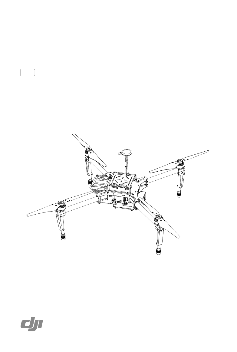
DJI MATRICE 100
User Manual
V1.0 2015.6
Page 2
Using This Manual
Legend
Warning Important Hints and Tips Reference
Information
The DJI Matrice 100 does not include a gimbal or camera. The DJI Zenmuse X3 Gimbal with Camera
is required for the gimbal and camera functions mentioned in this manual.
Before Flight
The following tutorials and manuals have been produced to ensure you make full use of your DJI
Matrice 100.
1.
DJI Matrice 100 In the Box
2.
DJI Matrice 100 Disclaimer and Safety Guidelines
3.
DJI Matrice 100 Intelligent Flight Battery Safety Guidelines
4.
DJI Matrice 100 User Manual
Check to see that you have all of the components listed in the
Before assembly, read the
with the help of this manual and the video tutorial on the DJI website (https://dev.dji.com).
DJI Matrice 100 Disclaimer and Safety Guidelines
DJI Matrice 100 In the Box
. Complete the assembly
Watch the Video Tutorials
Please watch the tutorial video below to learn how to install the
DJI Matrice 100 correctly:
https://dev.dji.com/products/ying-platforms/matrice-100/videos
Download the DJI Pilot app
Download and install the DJI Pilot app before use. Scan the QR code or visit
“http://m.dji.net/djipilot” to download the app.
For the best experience, use mobile devices with Android 4.1.2 or above.
Requires iOS 8.0 or later.
2015 DJI. All Rights Reserved.
2
©
manual.
Page 3

Warnings
The rotating propellers can cause serious damage and injury. Fly with caution at all times.
Assembly Warnings
1. Ensure that all other parts are installed before inserting the Intelligent Flight Battery.
2. Use the extension rod to separate the GPS module from the center frame to avoid interference with
the power board.
3. Ensure the frame arms are mounted correctly.
4. It is recommended to use the 3° fasteners to secure the frame arms. If you use the 0° fasteners,
ensure that all four propeller rotation planes are perfectly horizontal after mounting.
5. Do NOT mix up the 0° fasteners and the 3° fasteners. Ensure the four fasteners in the outer arm
slots of the center frame are the same.
6. Do NOT remove any glued-in screws.
7. Screws with blue glue on their threads can be used without threadlocker for the rst time. After that,
apply a suitable amount of threadlocker to the thread.
Flight Warnings
1. The aircraft is not waterproof. Do NOT y in rainy or snowy weather.
2. Ensure that all parts are in good condition before each ight. Do NOT y with worn or damaged
parts.
3. Ensure that the cooling fan of the ight controller is in good condition and working properly before
each ight. If not, repair it immediately.
4. Ensure the propellers and motors are installed correctly before each ight.
5. Ensure that all cables are secure before each ight.
6. Maintain a safe distance from people, buildings, high voltage power lines, tall trees, water, and
other hazards when ying the aircraft.
7. Use only DJI TB47D/TB48D Intelligent Flight Batteries as the power supply.
8. Do NOT overload the system.
9. Do NOT go near or touch the motors or propellers when they are spinning, as this can cause
serious injury.
10. Disconnect the battery and remove the camera during transportation to avoid damage or injury.
11. Only use compatible DJI parts.
If you encounter any problems or if you have any questions, please contact your
local DJI authorized dealer or DJI Support.
DJI Support Website:
www.dji.com/support
2015 DJI. All Rights Reserved.
©
3
Page 4

Contents
Using This Manual 2
Legend 2
Information 2
Before Flight 2
Watch the Video Tutorials 2
Download the DJI Pilot app 2
Warnings 3
Assembly Warnings 3
Flight Warnings 3
Product Prole 6
Installation 6
Checking the Frame Arms 6
Checking the Center Frame 6
Mounting the Frame Arms 7
Mounting the Battery Compartment 10
Mounting an Extra Battery Compartment 15
Mounting the Expansion Bay 15
Mounting the GPS Module 16
Reserved Ports Description 17
Attaching the Propellers 19
Mounting the Gimbal (Optional) 20
Using the DJI Intelligent Flight Battery 24
Introduction 24
DJI Intelligent Flight Battery Functions 24
Using the Battery 25
Using the Remote Controller 29
Remote Controller Prole 29
Preparing Remote Controller 29
Remote Controller Diagram 30
Remote Controller Operation 32
Dual Remote Controllers Mode 36
Setting Up Dual Remote Controllers Mode 37
Remote Controller Status LED 39
Linking the Remote Controller 40
2015 DJI. All Rights Reserved.
4
©
Page 5

DJI MATRICE 100 User Manual
Remote Controller Compliance 41
Return-to-Home (RTH) and Dynamic Home Point 42
Return-to-Home (RTH) 42
Dynamic Home Point 44
DJI Pilot App 45
Camera 45
Director 48
Store 48
User Center 48
Using the PC Assistant 49
Using the SDK 52
Flight 53
Flight Environment 53
Flight Limits and No Fly Zones 53
Pre-Flight Checklist 57
Flight Status Indicator 57
Calibrating the Compass 58
Auto Takeoff and Auto Landing 59
Starting and Stopping the Motors 59
Flight Test 60
Appendix 61
Product Specications 61
Aircraft Status Indicator Description 63
Intelligent Orientation Control (IOC) 64
Updating the Firmware 64
Component Dimensions 67
DJI Zenmuse X3 Gimbal with Camera 70
DJI Guidance System Mounting Warning 75
Compliance Information 76
FCC Warning Message 76
IC RSS Warning 76
KCC Warning Message 77
NCC Warning Message 77
2015 DJI. All Rights Reserved.
©
5
Page 6
Product Prole
M
The DJI Matrice 100 (abbreviated as M100) is a stable, exible, and powerful ying platform. Its open
platform and highly customizable design makes it suitable for a wide range of applications in the
areas of research, business, and recreation.
The M100’s expandable center frame makes it easy to mount additional components and devices to
achieve greater functionality and results. An extra battery compartment for a second Intelligent Flight
Battery can be installed to deliver an extended ight time of up to 40 minutes.
Developers are granted full control over their ying platform with the built-in API Control feature, giving
them the freedom to customize a comprehensive aerial solution by using the DJI SDK.
Installation
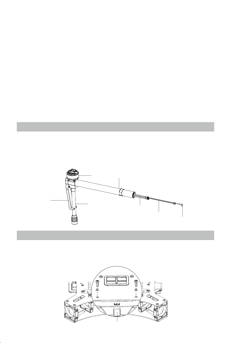
Checking the Frame Arms
1. Ensure the motors are rmly attached to the frame arms, and can rotate freely.
2. Ensure the landing gear is rmly attached to the frame arms, and the antenna covers are in good
condition.
3. Ensure that all cables are intact.
4. Identify the marks M1, M2, M3, and M4 on the four frame arms.
Motor M1 - M4 Mark
Antenna Cover
Landing Gear
Motor Cables
LED Cable
Antenna Cable
Checking the Center Frame
To check the center frame and connect the cables, first remove the upper plate and the battery
compartment.
1. Remove the two screws (M3x8 self-tapping) on the Aircraft Status Indicator. Then gently remove
the indicator to avoid damaging the cables.
Aircraft Status Indicator
2015 DJI. All Rights Reserved.
6
©
Page 7
DJI MATRICE 100 User Manual
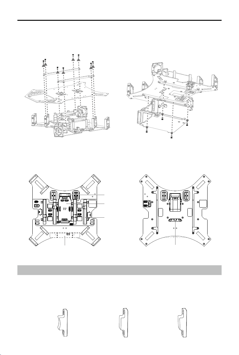
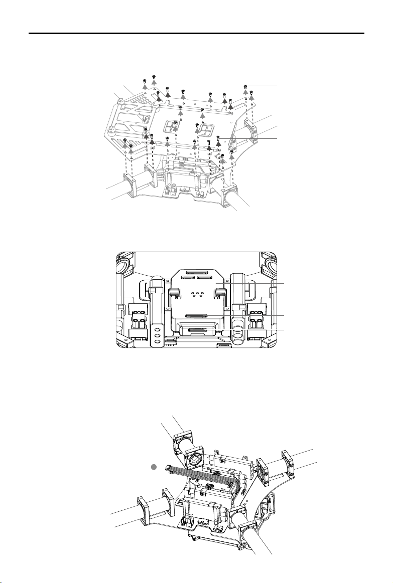
2. Remove the eight screws (M2.5x8) on the mounting rails on the upper plate of the center frame.
Then remove the mounting rails and the upper plate.
3. Remove the four screws (M2.5x5) on the battery compartment. Then remove the battery
compartment.
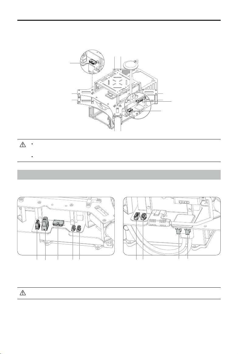
4. Now you may check the center frame. Check that components such as the ight controller and
ESCs are intact, and that the cables are connected to ports with matching color labels.
Cooling Fan
Flight Controller
ESC
Aircraft Status Indicator
Antenna Port
Mounting the Frame Arms
1. Identify the M1 - M4 marks on the frame arms and the arm slots of the center frame. Mount each
frame arm onto the corresponding position on the center frame.
2. Arm Fasteners are used to secure the frame arms. There are three types of fasteners that come
with the M100. The curved fasteners and the 3° fasteners are preinstalled on the arm slots.
Curved Fastener 0° Fastener
3° Fastener
2015 DJI. All Rights Reserved.
©
7
Page 8
DJI MATRICE 100 User Manual
Curved Fastener: Fix on the inner arm slot.
0° Fastener: Fix on the outer arm slot so that the propeller rotation plane is perfectly horizontal.
3° Fastener: Fix on the outer arm slot so that the propeller rotation plane is at a 3° incline. It is
recommended to use the 3° fasteners for a better ight experience.
Clamp Ring
Inner Arm Slot
Outer Arm Slot
1) Loosen the four M2.5x5 screws on the curved fastener and the 3° fastener on each of the frame arms.
2) Insert each frame arm into the outer and inner arm slots successively until the clamp ring reaches
the outer arm slot.
3) Rotate the frame arm so that the clamp ring fits perfectly into the side of the 3° fastener. Then
tighten the four screws to x the curved fastener and the 3° fastener in place. Ensure the arrow on
the 3° fastener is pointing upwards.
If you choose to use the 0° fasteners, remove the 3° fasteners from the arm slots rst. Ensure
that all propeller rotation planes are perfectly horizontal after mounting the 0° fasteners.
Do NOT mix up the 0° fasteners and the 3° fasteners. Ensure that the four fasteners on the
outer arm slots are the same.
The 3° Fastener (with marking) The 0° Fastener
2015 DJI. All Rights Reserved.
8
©
Page 9
DJI MATRICE 100 User Manual
M2 M1
M1
M2
M3
M4
M4M3
3. Connect the three motor cables of each motor (M1 - M4) to the ports of its corresponding ESC. Be
sure to match the color of the cables and ports.
4. Connect the LED cable of each frame arm to the port of its corresponding ESC.
LED Cable
M1 - M4 Mark
LED Port
Color Mark
Motor Cable
5. Pull the antenna cable of each frame arm through the cable tie on the lower plate of the center
frame, and then connect each cable to its corresponding antenna port on the bottom of the ight
controller (You may require some tools for this step). Note the arrangement of the antenna ports
shown below.
Antenna Cable
Antenna Port
Cable Tie
M2 M4 M3 M1
Antenna ports on the bottom of
the ight controller
6. Ensure the motor cables, LED cable, and antenna cable of each frame arm are correctly installed
to their corresponding ports.
Be sure to match the color of each motor cable with its corresponding port. Wrong connections
can cause the motor to rotate in the wrong direction.
After connecting the antenna cables, tighten the cable tie to prevent the cables from
coming loose.
7. Double check the positions of the frame arms.
Frame arms M1 and M2 form the front of the
aircraft, while frame arms M3 and M4 form its
rear. Seen from the top, motors on frame arms
M1 and M3 should rotate counter clockwise,
while motors on frame arms M2 and M4
should rotate clockwise.
2015 DJI. All Rights Reserved.
©
9
Page 10
DJI MATRICE 100 User Manual
Mounting the Battery Compartment
Standard Mounting Position - Under the Center Frame
If you are using the DJI Guidance system, it is recommended to mount the battery
compartment on top of the center frame to avoid interference with the Guidance system. If
you choose to mount the battery compartment under the center frame, disconnect the cable
of the Guidance Sensor before accessing the Intelligent Flight Battery.
The aircraft has been designed so that its center of gravity is optimized for the standard
mounting position of the battery compartment. However, there is the option to adjust the
longitudinal center of gravity by mounting the battery compartment at different positions along
the top of the center frame. Refer to the next section on Optional Mounting Position (P12) for
more details.
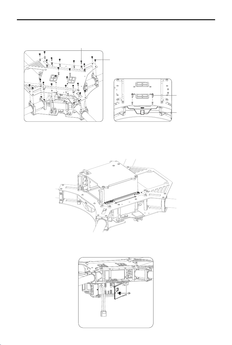
1. Pull the Aircraft Status Indicator cable, CAN cable, signal cable and power cable of the flight
controller through the wire outlet on the lower plate of the center frame (refer to the right wire outlet
in the gure below).
Flight Controller Power Cable (4-pin)
CAN Cable (5-pin)
Aircraft Status Indicator
Flight Controller Signal Cable (6-pin)
Aircraft Status Indicator Cable (6-pin)
Wire Outlet
2. Re-mount the upper plate onto the center frame, and tighten the 16 screws (M2.5x5). Orientate the
upper plate so that the notch faces the left of the aircraft (with its tail facing you). Then mount the
mounting rails, and tighten the 8 screws (M2.5x8).
If you are using the DJI Zenmuse X3 Gimbal with Camera, install the gimbal before mounting
the upper plate. Refer to Mounting the Gimbal (P20) for more details.
2015 DJI. All Rights Reserved.
10
©
Page 11
DJI MATRICE 100 User Manual
3. Re-mount the Aircraft Status Indicator, and tighten the two screws (M3x8 self-tapping). Do not
overtighten the screws to avoid damaging the threads.
M2.5x8
M2.5x5
M3x8 self-tapping
Aircraft Status Indicator
4. Mount the battery compartment (with the metal terminals facing the tail of the aircraft) onto the
mounting rails on the lower plate of the center frame. Then tighten the four screws (M2.5x5).
M2.5x5
Lower Plate
Metal Terminals
2015 DJI. All Rights Reserved.
©
11
Page 12

DJI MATRICE 100 User Manual
Optional Mounting Position - On Top of the Center Frame
1. Take the Aircraft Status Indicator cable, CAN cable, signal cable and power cable of the ight
controller out of its existing wire outlet. Pull the cables through the wire outlet on the upper plate of
the center frame instead.
Flight Controller Power Cable (4-pin)
CAN Cable (5-pin)
Flight Controller Signal Cable (6-pin)
Aircraft Status Indicator Cable (6-pin)
Aircraft Status Indicator
Upper Plate
Wire Outlet
2. Re-mount the upper plate onto the center frame and tighten the 16 screws (M2.5x5). Orientate the
upper plate so that the notch faces the left of the aircraft (with its tail facing you). Then mount the
mounting rails and tighten the 8 screws (M2.5x8).
If you are using the DJI Zenmuse X3 Gimbal with Camera, install the gimbal before mounting
the upper plate. Refer to Mounting the Gimbal (P20) for more details.
2015 DJI. All Rights Reserved.
12
©
Page 13
DJI MATRICE 100 User Manual
3. Re-mount the Aircraft Status Indicator and tighten the two screws (M3x8 self-tapping). Do not
overtighten the screws to avoid damaging the threads.
M2.5x8
M2.5x5
M3x8 self-tapping
Aircraft Status Indicator
4. Mount the battery compartment (with the metal terminals facing the tail of the aircraft) onto the
mounting rails on the upper plate of the center frame.
5. Adjust the aircraft’s center of gravity by changing the position of the battery compartment along the
mounting rails. Then tighten the four screws (M2.5x5).
Cable Connection
1. Open the battery cover by removing the screw on the side of the battery compartment.
2015 DJI. All Rights Reserved.
©
13
Page 14
DJI MATRICE 100 User Manual
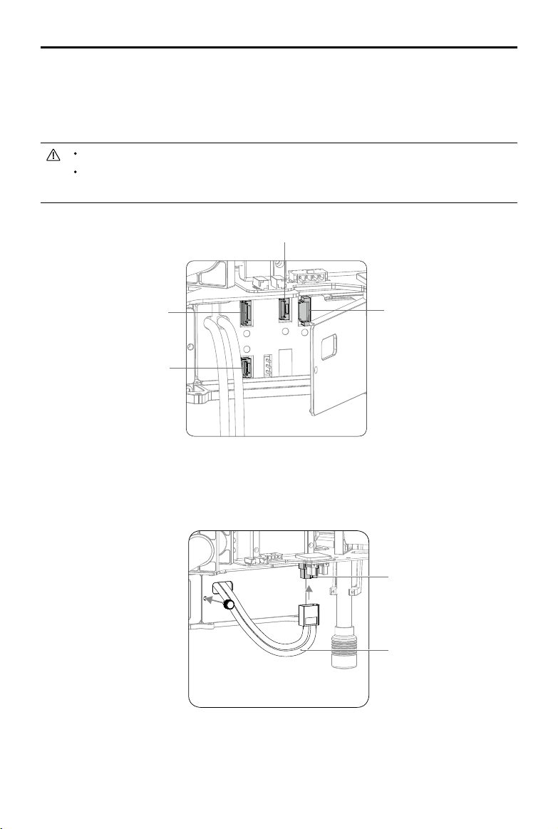
2. Connect the Aircraft Status Indicator cable to the 6-pin port.
3. Connect the power cable of the ight controller to the 4-pin port.
4. Connect the signal cable of the ight controller to the 6-pin port.
5. Connect the CAN cable on the lower plate to the CAN1 port.
The 6-Pin port with a yellow sticker is reserved. Do NOT connect any cables to this port.
Pull the above cables through the opening behind the battery cover, towards the nose of
the aircraft, before connecting them.
CAN1 Port (5-pin)
Port for the Flight Controller
Signal Cable (6-pin)
Port for the Flight Controller
Power Cable (4-pin)
Aircraft Status Indicator
Cable Port (6-pin)
6. Pull the battery’s power cable through the hole on the battery cover, and then connect it to the
XT60 port on the center frame.
7. Close the battery cover and tighten the screw.
XT60 Port
Power Cable of the Battery
2015 DJI. All Rights Reserved.
14
©
Page 15
DJI MATRICE 100 User Manual
Mounting an Extra Battery Compartment
It is recommended to mount the extra battery compartment on the opposite side of the center frame.
An extension cord may be required to connect the battery’s power cable to the center frame.
1. Mount the battery compartment (with the metal terminals facing the tail of the aircraft) onto the
mounting rails on the center frame. Then tighten the four screws (M2.5x5).
2. Connect the battery’s power cable to the XT60 port on the center frame.
When using two batteries, ensure that they have similar power levels.
Always power on the battery which is connected to the ight controller rst, otherwise the
ight controller will not function properly.
If the extra battery compartment is empty or if the Intelligent Flight Battery in the extra
battery compartment is powered off, disconnect the battery power cable from the center
frame before ight to avoid a short circuit.
When updating the battery firmware, insert the Intelligent Flight Battery into the battery
compartment which is connected to the ight controller. Update the rmware via the DJI
N1 Assistant or a Micro SD card. Read Updating the Firmware (P64) in the Appendix for
details.
Mounting the Expansion Bay
Extend the center frame of the M100 with the expansion bay to mount DJI modules such as the
Guidance system or other products if necessary. Depending on your conguration, the expansion bay
can be positioned on the top or bottom of the center frame, and mounted onto the mounting rails or
the battery compartment.
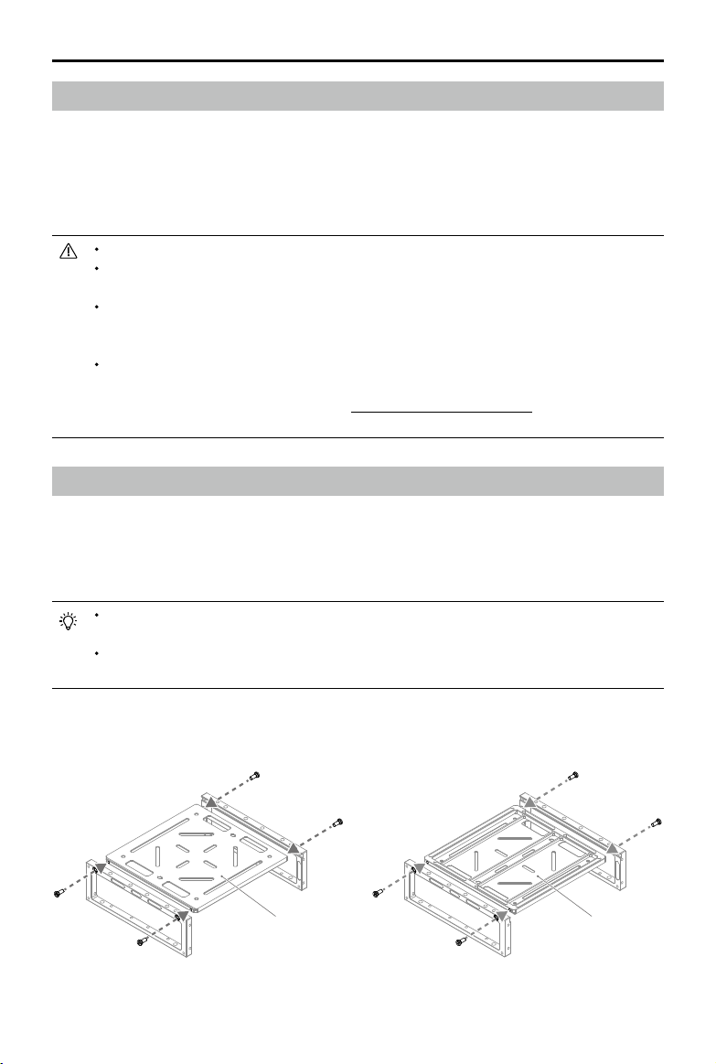
Only one side of the expansion bay base plate is smooth. Attach your gear to the smooth
side of the base plate.
Two sets of expansion bays come with the M100. One of them has mounting marks and a
direction arrow to help you mount the DJI Guidance system.
1. Slide the base plate of the expansion bay into the slots of the two side plates. Then tighten the four
screws (M2.5x5).
Smooth Not Smooth
2015 DJI. All Rights Reserved.
©
15
Page 16
DJI MATRICE 100 User Manual
2. Mount the expansion bay onto the mounting rails and tighten the four screws (M2.5x5).
Alternatively, mount the expansion bay onto the battery compartment and tighten the four screws
(M3x5). The two mounting methods are illustrated in the gures below.
Mounting the expansion bay onto
the mounting rails
Mounting the expansion bay onto
the battery compartment
3. Join two adjacent expansion bays using four screws (M3x5) as shown below.
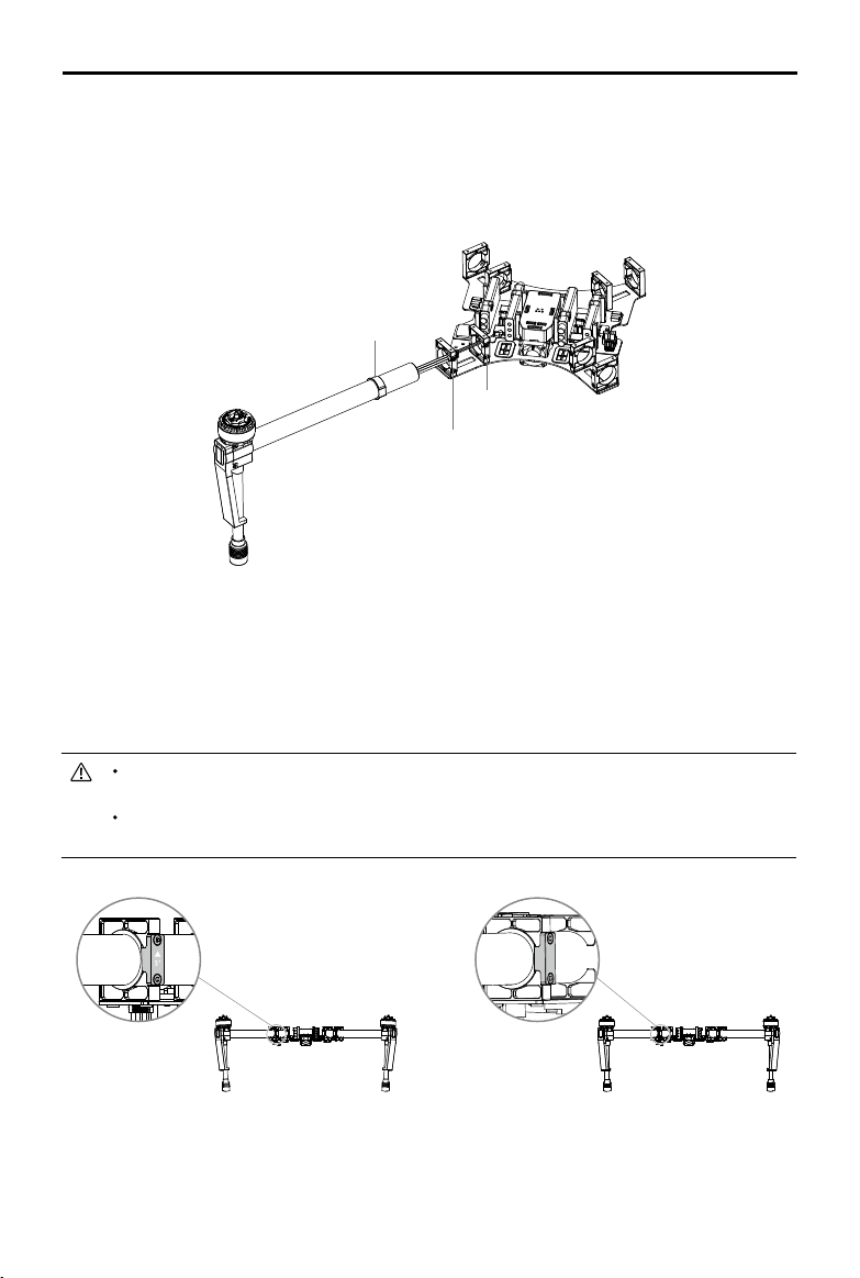
Mounting the GPS Module
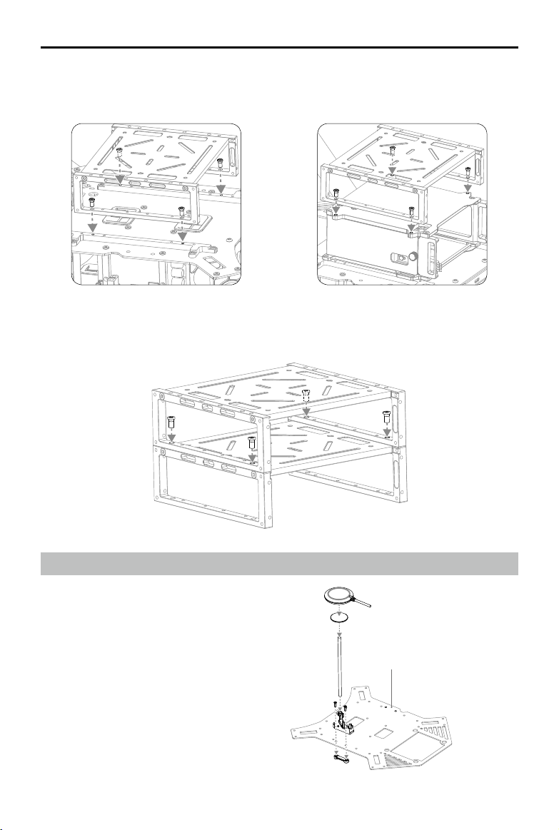
1. Mount the collapsible GPS mount onto either
side of the center frame using M2.5×8 screws.
2. Use the extension rod to attach the GPS
module to the collapsible GPS mount. Ensure
the arrow on the GPS module points to the
nose of the aircraft (M1, M2). Avoid catching
your fingers in the bracket when folding the
collapsible GPS mount for transportation.
Other Mounting Position
M2
2015 DJI. All Rights Reserved.
16
©
M1
Page 17
DJI MATRICE 100 User Manual
3. Mount the CAN HUB of the GPS module onto the upper or lower plate of the center frame.
4. Connect the GPS cable to the GPS CAN port on the center frame.
GPS CAN Port
(Reserved)
CAN HUB
GPS CAN Port
Use the extension rod to separate the GPS module from the center frame power board to
avoid interference.
Use glue to install the GPS extension rod. Ensure it is rm and stable before every ight.
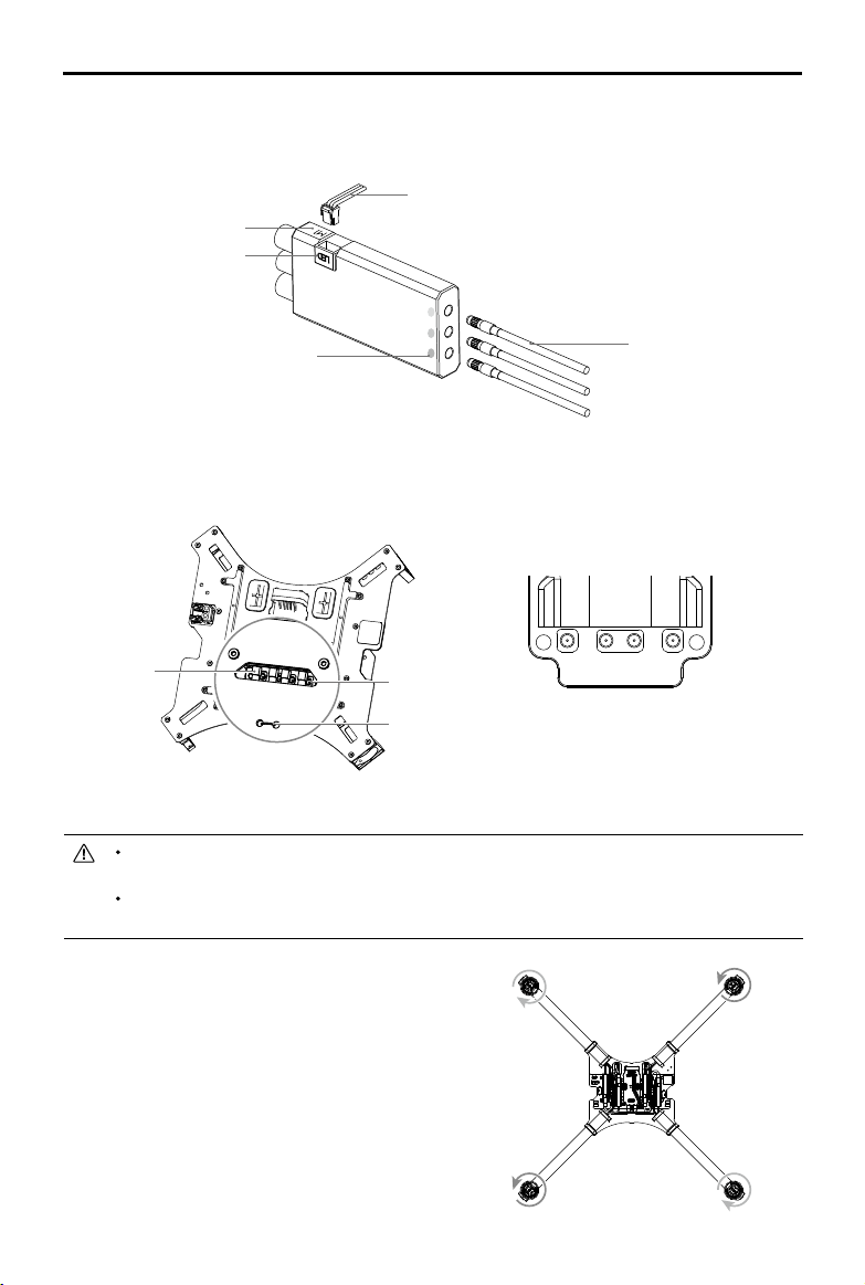
Reserved Ports Description
There are ve types of ports on the center frame. Connect your own devices to them accordingly.
[1]
[1] [2] [3] [4] [5]
[5] [4]
[1]
[1] XT30 Port [2] XT60 Port [3] GPS CAN Port [4] CAN-Bus Port [5] UART Port
Connect your own devices in strict accordance with the specications of the reserved ports.
XT30 Ports and XT60 Ports
There are three XT30 ports and one XT60 port reserved on the center frame. You can supply power to
your own devices by connecting them to these ports. Use the XT30-XT60 cable if necessary. Identify
the positive and negative terminals of each port before connecting your device.
2015 DJI. All Rights Reserved.
©
17
Page 18
DJI MATRICE 100 User Manual
The specications of these four reserved ports are as shown below:
Output Voltage: 20 - 26.1 V
Max Continuous Output Current: 10 A
The TOTAL current output of the reserved XT60 and XT30 ports (not including the XT60 port
for the standard battery compartment) must not exceed 10 A.
CAN Ports and UART Ports
There is one GPS CAN port, two CAN-Bus ports (5-pin), and two UART ports (6-pin) reserved on the
center frame. You can connect your own devices to these ports as required.
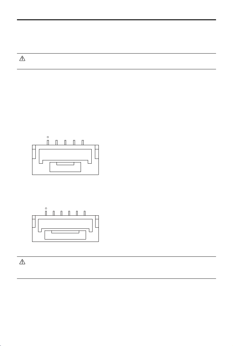
The pinout diagrams of the CAN-Bus port and the UART port are as shown below:
CAN-Bus Port (with a white dot besides pin 1):
[1] [2] [3] [4] [5]
[1] GND
[2] CANL
[3] CANH
[4] GND
[5] VCC 7.4 V
UART Port (with a white dot besides pin 1) :
[1] [2] [3] [4] [5] [6]
[1] UART TXD
[2] UART RXD
[3] GND
[4] CANL
[5] CANH
[6] VCC 6 V
Only use the provided UART cable to connect your own device to the UART port, as other
cables can cause the ight controller or your device to be damaged from high voltage. DJI
accepts no liability for damage or injury incurred from using third party cables.
2015 DJI. All Rights Reserved.
18
©
Page 19
DJI MATRICE 100 User Manual
Attaching the Propellers
Propeller Safety
1. Attach the propellers onto the correct motors stated in this manual. Rotation indicators are found on
both the motors and the propellers to help you determine their direction of rotation. Show vigilance
when attaching or detaching the propellers.
2. The propellers and the mounting plates may show signs of wear after continuous use. Inspect the
hooks inside the propeller nut and the mounting plate, and replace the propeller or the mounting
plate if necessary. If you have trouble identifying signs of wear, read Step 3 in the Installation
section for more details.
Hook
Mounting Plate
3. Ensure the mounting plate and the securing spring are rmly attached to the motor before every
ight.
4. Ensure that all propellers are in good condition before every ight. Do NOT use old, chipped, or
broken propellers.
5. Propellers should never be used after they have been involved in a crash or a collision. If such an
event occurs, replace the propellers before ying again.
6. To avoid injury, stand clear of the propellers and motors when they are spinning.
7. The propellers, securing springs, and mounting plates have an approximate lifespan of 200 ights.
Inspect them regularly to determine if they need replacement.
8. Only use ofcial DJI propellers for a safer and better ying experience.
9. Handle the propellers with care.
10. Always follow the prescribed storage procedures to avoid damaging the propellers.
Installation
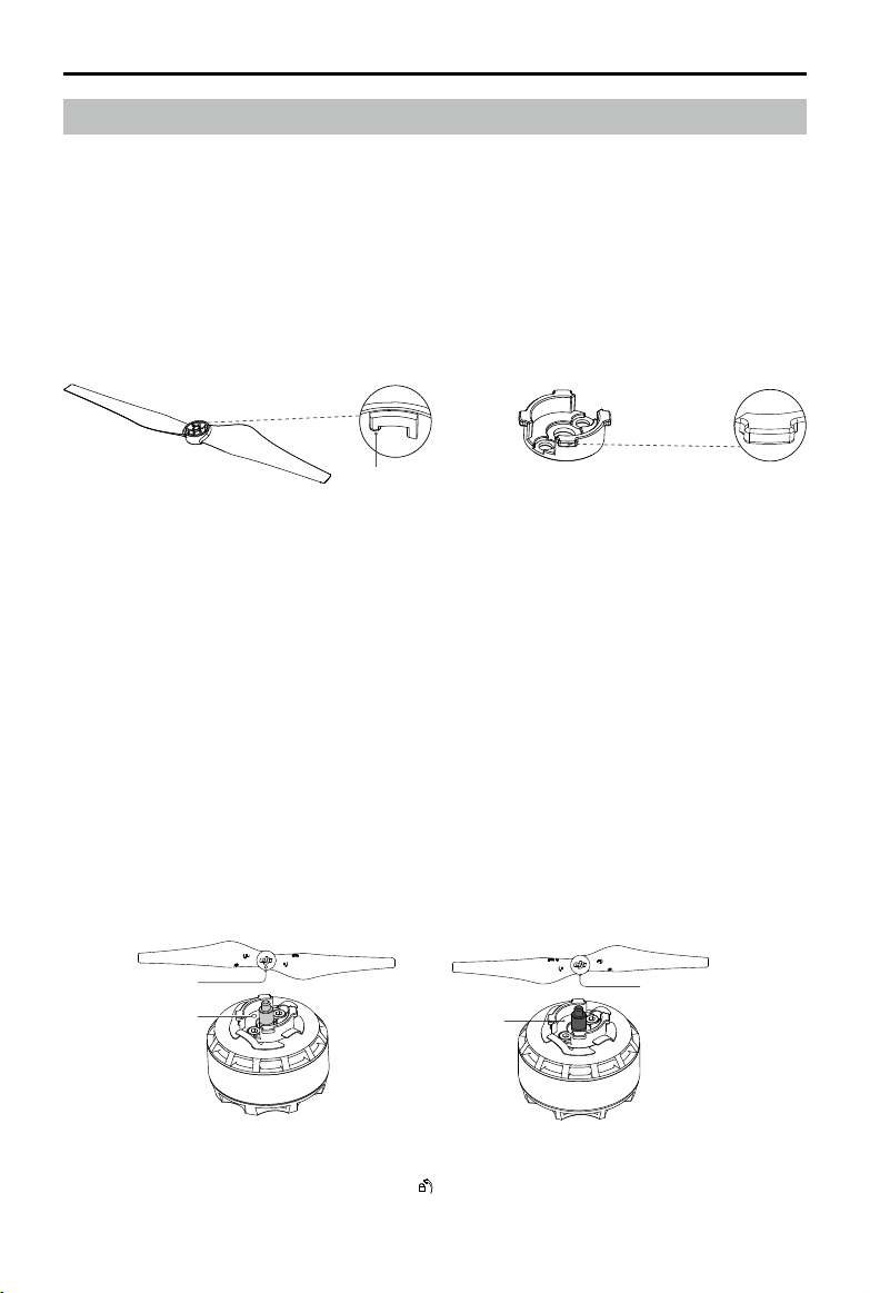
1. Attach the propellers with a white dot onto the mounting plate with a white dot, and attach the
propellers without a dot onto the mounting plate without a dot.
White Dot
White Dot
No Dot
No Dot
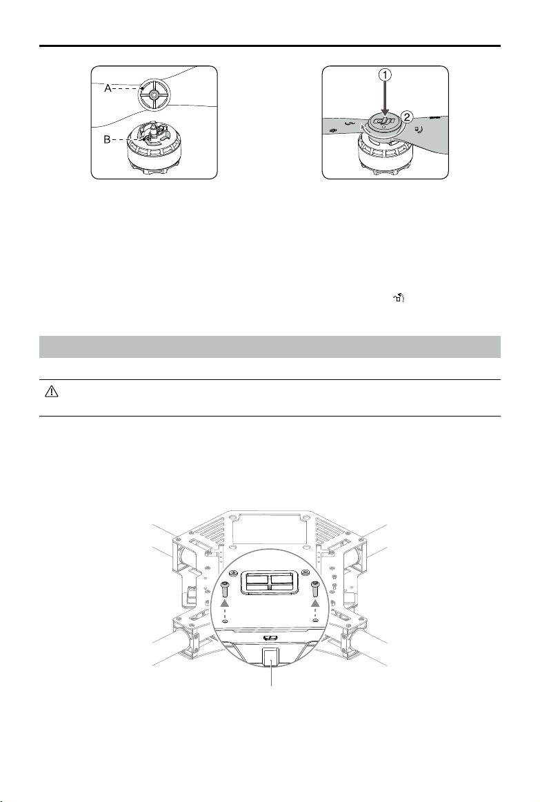
2. Align the hook (A) with the securing spring (B). While pressing the propeller onto the mounting
plate, rotate the propeller in the lock direction
until it is secured.
2015 DJI. All Rights Reserved.
©
19
Page 20
DJI MATRICE 100 User Manual
3. Ensure you have followed the previous steps to install the propellers onto their corresponding
mounting plates securely. To ensure the propellers are properly secured, hold the motor in place
with one hand and use your other hand to rotate the propeller in the unlock direction without
pressing down. If the propeller can be removed this way, the propeller and/or the mounting plate
may have become worn and need to be replaced.
Press down on the propellers rmly, and then rotate it in the unlock direction
motor.
to detach it from the
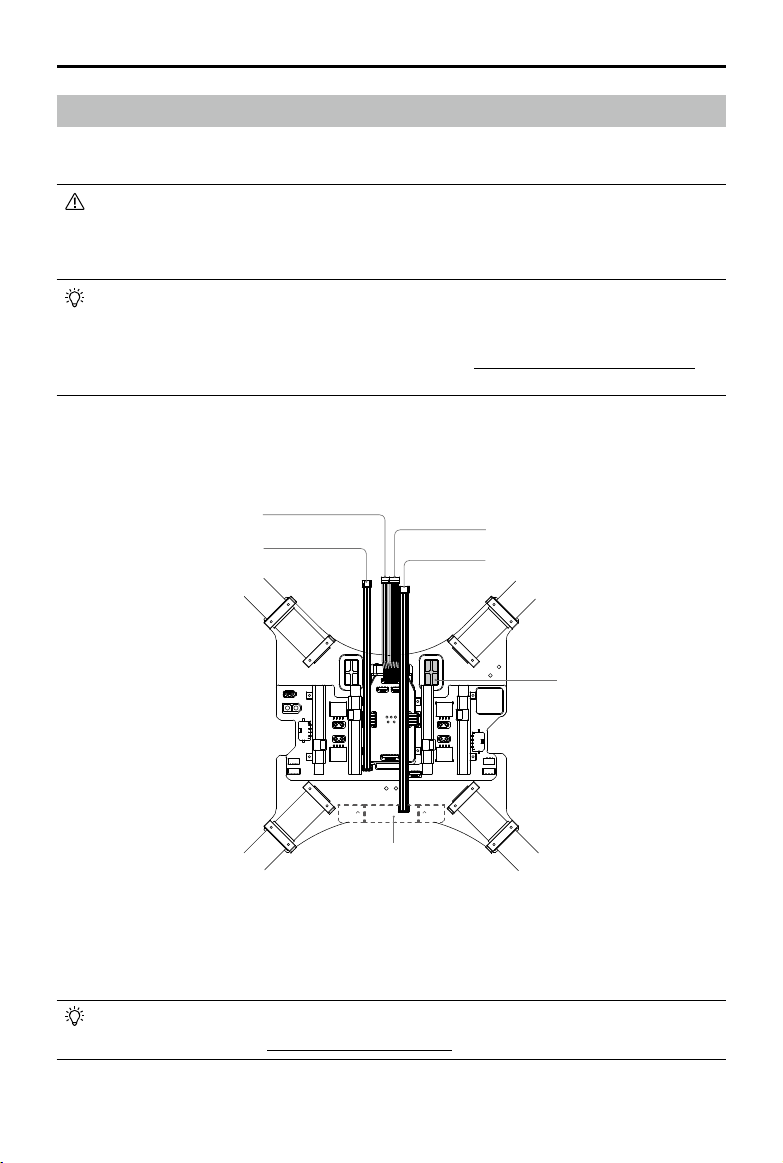
Mounting the Gimbal (Optional)
The M100 is only compatible with the DJI Zenmuse X3 Gimbal with Camera. Do NOT use
other gimbals.
Mounting the Gimbal Lock and Connecting the Cables
1. Remove the two screws (M3x8 self-tapping) on the Aircraft Status Indicator, and then remove the
indicator gently to avoid damaging the cables.
Aircraft Status Indicator
2015 DJI. All Rights Reserved.
20
©
Page 21
DJI MATRICE 100 User Manual
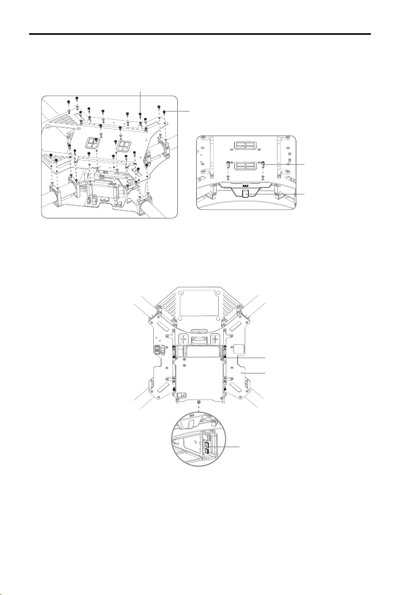
2. Remove the 16 screws (M2.5x5) on the upper plate of the center frame, and the eight screws
(M2.5x8) on the mounting rails. Then remove the mounting rails and the upper plate.
M2.5x5
M2.5x8
3. Connect one end of the 10-pin gimbal cable and 8-pin gimbal cable to the ight controller.
Flight Controller
10-pin Port
8-pin Port
4. Arrange the other ends of the gimbal cables near the nose of the aircraft.
Aircraft’s Nose
2015 DJI. All Rights Reserved.
©
21
Page 22
DJI MATRICE 100 User Manual
5. Re-mount the upper plate of the center frame, and tighten the 16 screws (M2.5x5). Orientate the
upper plate so that the notch faces the left of the aircraft (with its tail facing you). Then place the
mounting rails and tighten the 8 screws (M2.5x8).
6. Re-mount the Aircraft Status Indicator, and tighten the two screws (M3x8 self-tapping). Do not
overtighten the screws to avoid damaging the threads.
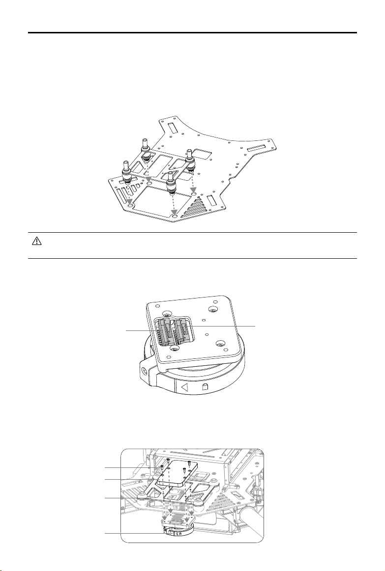
7. Mount the gimbal mounting plate and dampers to the center frame.
The dampers may deteriorate over time. Ensure that all dampers are in good condition before
every ight. Do NOT use worn or broken dampers.
8. Connect the other ends of the 10-pin gimbal cable and 8-pin gimbal cable to the corresponding
ports on the Gimbal Lock.
10-pin Port
Gimbal Lock
8-pin Port
9. Place the gimbal cable cover on the gimbal mounting plate. Attach the Gimbal Lock under the
gimbal mounting plate. Then tighten the four Phillips screws.
Phillips Screws
Gimbal Cable Cover
Gimbal Mounting Plate
Gimbal Lock
2015 DJI. All Rights Reserved.
22
©
Page 23
DJI MATRICE 100 User Manual
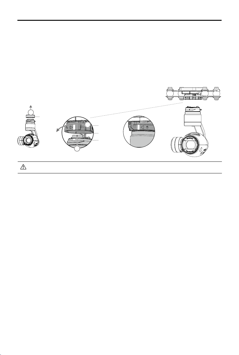
The quick-release mount of the DJI Zenmuse X3 Gimbal with Camera allows you to attach and detach
the camera with ease. Follow the instructions below:
Mounting the Gimbal and Camera:
1. Remove the Gimbal Cover.
2. Rotate the Gimbal Lock to the unlocked position. Insert the gimbal by aligning the white marks on
the gimbal and Gimbal Lock.
3. Rotate the Gimbal Lock back to the locked position. Ensure the gimbal is locked securely.
1
Gimbal Cover
3
Gimbal Lock
Mounting Place
Gimbal Connector
2
Locked
Ensure the Micro SD card is inserted into the camera.
Removing the Gimbal and Camera:
While holding the upper part of the gimbal, rotate the Gimbal Lock to the unlocked position to remove
the gimbal.
2015 DJI. All Rights Reserved.
©
23
Page 24
Using the DJI Intelligent Flight Battery
Introduction
The DJI Intelligent Flight Battery has a capacity of 4500mAh, voltage of 22.2V, and built-in smart
charge-discharge functionality. It can only be charged with an appropriate DJI approved charger.
Intelligent Flight Battery
The Intelligent Flight Battery must be fully charged before using it for the rst time. Refer to
Charging the Intelligent Flight Battery (P27) for more information.
Charger
DJI Intelligent Flight Battery Functions
1. Battery Level Display: LEDs display the current battery level.
2. Battery Life Display: LEDs display the current battery life.
3. Auto-discharging Function: The battery automatically discharges to below 65% of total power
when it is left idle (pressing the power button will cause the battery to exit idle state) for more than
10 days to prevent swelling. It takes about two days to discharge the battery from 100% to 65%,
and it is normal to feel moderate heat emitting from the battery during the discharge process. The
discharge thresholds can be adjusted in the DJI Pilot app.
4. Balanced Charging: Automatically balances the voltage of each battery cell when charging.
5. Overcharge Protection: Automatically stops charging the battery when it is fully charged.
6. Temperature Detection: The battery will only charge when its temperature is between 0°C (32°F)
and 40°C (104°F).
7. Overcurrent Protection: The battery stops charging when the maximum current of 10A is exceeded.
8. Over-Discharge Protection: The battery stops discharging when the battery voltage reaches 18V to
prevent damage from over-discharge.
9. Short Circuit Protection: Automatically cuts the power supply when a short circuit is detected.
10. Battery Cell Damage Detection: The DJI Pilot app shows a warning message if a damaged
battery cell is detected.
11. Battery Log: Show the last 32 entries of battery information including the warning messages.
12. Sleep Mode: The battery enters sleep mode after 10 minutes of inactivity to save power.
13. Communication: The battery voltage, capacity, current, and other relevant information is sent to
the ight controller.
Read the
before use. Users take full responsibility for all operations and usage.
2015 DJI. All Rights Reserved.
24
©
Disclaimer and Safety Guidelines
and
Intelligent Flight Battery Safety Guidelines
Page 25

DJI MATRICE 100 User Manual
Using the Battery
Installing the Battery
Insert the Intelligent Flight Battery into the battery compartment as shown below.
Never insert the Intelligent Flight Battery into or remove it from the battery compartment of the
M100 when it is powered on.
Powering On/Off the Battery
LED4
LED2
Power Button (Built-in LED)
LED3
LED1
Powering On: Press the Power Button once, then press again and hold for 2 seconds to power on.
The Power LED will turn red and the Battery Level Indicators will display the current battery level.
Powering Off: Press the Power Button once, then press again and hold for 2 seconds to power off.
Low Temperature Notice:
1. Using the Intelligent Flight Battery at core temperatures below -10℃ is not advised. Between -10℃
and 5℃, the Intelligent Flight Battery should attain a voltage of 4.2 V, but it is recommended that
you apply the insulation sticker to the battery to prevent a rapid drop in temperature.
2. In cold environments (i.e. air temperature below 5℃), the performance of the Intelligent Flight
Battery is reduced. Ensure the Intelligent Flight Battery is fully charged and attains a voltage of 4.35
V before takeoff.
2015 DJI. All Rights Reserved.
©
25
Page 26

DJI MATRICE 100 User Manual
3. In very cold environments (e.g. air temperature of -20℃, battery core temperature of 5℃), the
Intelligent Flight Battery’s core temperature will drop rapidly even after pre-heating, and its
performance is signicantly reduced. It is not recommended to y under such conditions.
4. If the DJI Pilot app displays the Low Battery Level warning, stop flying and land the aircraft
immediately. You will still be able to control the aircraft’s movement when this warning is triggered.
5. For the optimal performance, maintain the Intelligent Flight Battery’s core temperature above 20℃
when in use.
Ensure the temperature of the Intelligent Flight Battery exceeds 5℃ before takeoff.
To warm up the battery, power on the Intelligent Flight Battery inside the battery compartment,
for approximately 1-2 minutes, before takeoff. Begin ying by hovering the aircraft at a low
altitude, for approximately 1 minute, to ensure the battery temperature is stable.
Checking the Battery Level
The Battery Level Indicator show how much battery capacity is remaining. When the battery is
powered off, press the power button once. The Battery Level Indicator will light up to display the
current battery level. See the table below for details.
The Battery Level Indicator will show the current battery level during charging and discharging.
Its LEDs can exhibit the following behavior.
: LED is on. : LED is blinking.
: LED is off.
Battery Level Indicator
LED1 LED2 LED3 LED4 Battery Level
87.5%~100%
75%~87.5%
62.5%~75%
50%~62.5%
37.5%~50%
25%~37.5%
12.5%~25%
0%~12.5%
=0%
Checking the Battery Life
The battery life indicates the number of cycles the battery can be charged and discharged before it
must be replaced. When the battery is powered off, press and hold the power button for 5 seconds
to check the battery life. The Battery Level LEDs will light up and/or blink as described below for 2
seconds:
2015 DJI. All Rights Reserved.
26
©
Page 27

DJI MATRICE 100 User Manual
Battery Life
LED1 LED2 LED3 LED4 Battery Life
90%~100%
80%~90%
70%~80%
60%~70%
50%~60%
40%~50%
30%~40%
20%~30%
below 20%
When the battery life reaches 0%, it can no longer be used.
For more information about the battery, launch the DJI Pilot app and go to the Battery tab.
Charging the Intelligent Flight Battery
1. Connect the battery charger to a suitable power supply (100-240V 50/60Hz).
2. Open the protection cap and connect the Intelligent Flight Battery to the battery charger. If the
battery level is above 95%, turn on the battery before charging.
3. The Battery Level Indicator will display the current battery level during charging.
4. The Intelligent Flight Battery is fully charged when Battery Level Indicators are all off. Disconnect
the Intelligent Flight Battery from the battery charger.
Do NOT charge the Intelligent Flight Battery and the remote controller (model: A14-100P1A)
at the same time to avoid overloading the battery charger.
Air cool the Intelligent Flight Battery after each ight. Allow its temperature to drop to room
temperature before charging.
The charging temperature range is 0 to 40℃. The battery management system will stop the
battery from charging when the battery cell temperature is out of range.
Power Outlet
Intelligent Flight Battery
Charger
2015 DJI. All Rights Reserved.
©
27
Page 28

DJI MATRICE 100 User Manual
Battery Level Indicator While Charging
LED1 LED2 LED3 LED4 Battery Level
0%~25%
25%~50%
50%~75%
75%~100%
Fully charged
Charging Protection LED Display
The table below describes the battery protection mechanisms and their corresponding LED patterns.
Battery Level Indicator While Charging
LED1 LED2 LED3 LED4 Indicators Pattern Battery Protection Item
LED2 blinks twice per second Overcurrent detected
LED2 blinks three times per second Short circuit detected
LED3 blinks twice per second Overcharge detected
LED3 blinks three times per second Charger overvoltage detected
LED4 blinks twice per second
LED4 blinks three times per second
Charging temperature is too
low (<0°C)
Charging temperature is too
high (>40°C)
After any of the above protection issues are resolved, press the power button to turn off the Battery
Level Indicator. Unplug the Intelligent Flight Battery from the battery charger and plug it back in to
resume charging. Note that you do not need to unplug and plug the battery charger in the event of a
room temperature error; the battery charger will resume charging when the temperature falls within the
normal range.
DJI does NOT take any responsibility for damage caused by third-party battery chargers.
Calibrating the Battery Capacity:
To effectively calibrate the capacity of the Intelligent Flight Battery, it is recommended to
charge and discharge the battery thoroughly for every 10 charge-and-discharge cycles.
Choose one of the following methods to discharge battery. After discharging the battery, fully
charge the battery to nish the calibration.
Slow: Place the battery into the M100’s battery compartment and power it on. Leave it on until
there is less than 5% battery level, or until it can no longer be turned on. Check the battery
level in the DJI Pilot app.
Fast: Fly the M100 outdoors until there is less than 5% battery level, or until the battery can no
longer be turned on.
2015 DJI. All Rights Reserved.
28
©
Page 29

Using the Remote Controller
Remote Controller Prole
The remote controller integrates video downlink and aircraft control into one system. The combined
system operates at 2.4 GHz with a maximum signal transmission range of 2 km. The device features
a number of standard and customizable buttons that allow users to quickly access certain aircraft
functions, such as taking and reviewing photos/videos, as well as controlling the gimbal motion. It is
powered by a 2S rechargeable battery.
Compliance Version: The remote controller is compliant with both CE and FCC regulations.
Operating Mode: Control can be set to Mode 1, Mode 2, or a custom mode in the DJI Pilot app.
Mode 1: The right stick serves as the throttle.
Mode 2: The left stick serves as the throttle.
Do NOT operate more than 3 aircrafts within in the same area (size equivalent to a soccer
eld) to prevent transmission interference.
Preparing Remote Controller
Mounting the Mobile Device Holder:
1. Unfold the Mobile Device Holder . Remove the screw using the slotted screwdriver coming with
the M100 .
2. Plug the Mobile Device Holder into the remote controller and tighten the screw lock.
3. Line up the hole on the Mobile Device Holder with the metal loop on the remote controller. Insert
and tighten the screw.
Mounting Hole
Metal Loop
Screw Lock
2015 DJI. All Rights Reserved.
©
29
Page 30

DJI MATRICE 100 User Manual
Tilt the Mobile Device Holder to the desired position and then adjust the antenna as shown. Follow
the instructions below to connect your mobile device to the remote controller:
1. Press the button on the side of the Mobile Device Holder to release the clamp.
2. Place your mobile device inside the clamp and adjust it to secure your mobile device.
3. Connect your mobile device to the remote controller via a USB cable.
Remote Controller Diagram
[3] Control Stick
Controls the aircraft movement.
[4] Return-to-Home (RTH) Button
Press and hold this button to initiate
Return-to-Home (RTH).
[5] RTH LED
Circular LED around the RTH button
which displays the RTH status.
[6] Battery Level LEDs
Display the current battery level.
[7] Status LED
Indicates whether the remote controller
is linked to the aircraft.
[8] Power Button
Used to power on/off the remote controller.
[8]
[7]
[1] Antennas
Relays the aircraft control and video signals.
[2] Mobile Device Holder
Mounting place for your mobile device.
[1]
[2]
[3]
[4]
[5]
[6]
2015 DJI. All Rights Reserved.
30
©
Page 31

DJI MATRICE 100 User Manual
[15] [16] [17] [18]
[14]
[13]
[12]
[9] Camera Settings Dial
Turn the dial to adjust the camera settings.
Only functions when the remote controller is
connected to a mobile device running the
DJI Pilot app.
[10] Playback Button
Play back the captured images or videos.
[11] Shutter Button
Press to take a photo. If in burst mode, the
[9]
[10]
[11]
preset number of photos will be taken
with one press.
[12] Flight Mode Switch
Used to switch between P-Mode
(Positioning), A-Mode (Attitude) and
F-Mode (Function).
[13] Video Recording Button
Press to start recording video. Press
again to stop recording.
[14] Gimbal Dial
Used to control the pitch of the gimbal.
[15] Micro-USB Port
Reserved for future use.
[16] Mini-HDMI Port
Connect an HD compatible monitor to
this port to get a live HD video preview
of what the camera sees.
[17] CAN Bus Port
Reserved for future use.
[18] USB Port
Connects to your mobile device to
access all of the DJI Pilot app controls
and features.
[22]
[21]
[19]
[20]
[19] GPS Module
Used to pinpoint the location of the
remote controller.
[20] Back Left Button C1
Customizable button in the DJI Pilot app.
[21] Power Port
Connects to a power source to charge
the remote controller’s internal battery.
[22] Back Right Button C2
Customizable button in the DJI Pilot app.
2015 DJI. All Rights Reserved.
©
31
Page 32

DJI MATRICE 100 User Manual
Remote Controller Operation
Powering On and Off the Remote Controller
The M100 remote controller is powered by a 2S rechargeable battery with a capacity of 6000mAh.
The battery level is indicated by the Battery Level LEDs on the front panel. Follow the steps below to
power on/off your remote controller:
1. Press the power button once. The Battery Level LEDs will display the current battery level.
2. Press again and hold to power on the remote controller.
3. The remote controller will beep when it powers on. The Status LED will blink green rapidly,
indicating that the remote controller is linking to the aircraft, then turn solid green when linking is
complete.
4. Press twice and hold the power button to power off the remote controller.
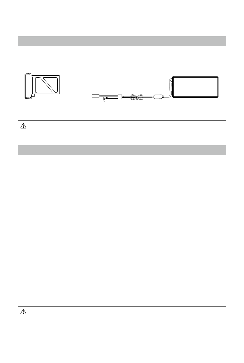
Charging the Remote Controller
Charge the remote controller via the provided charger.
2015 DJI. All Rights Reserved.
32
©
Power Outlet
Charger
Page 33

DJI MATRICE 100 User Manual
Controlling the Camera
Shoot videos or images and adjust the camera settings via the Shutter Button, Camera Settings Dial,
Playback Button and Video Recording Button on the remote controller.
[1]
[4]
[2]
[3]
[1] Camera Settings Dial
Turn the dial to quickly adjust camera settings such as ISO and shutter speed without letting go
of the remote controller. In Playback Mode, the dial button can be used to review the images or
videos.
[2] Playback Button
Press to view images or videos that have already been captured.
[3] Shutter Button
Press to take a photo. If burst mode is activated, multiple photos will be taken with a single press.
[4] Recording Button
Press once to start recording video, then press again to stop recording.
Controlling the Aircraft
This section explains how to use the various features of the remote controller. Mode 2 (throttle stick on
the left) is set by default.
2015 DJI. All Rights Reserved.
©
33
Page 34

DJI MATRICE 100 User Manual
Remote Controller
(Mode 2)
Aircraft ( indicates nose direction) Function
Moving the Left Stick up/down changes
the aircraft’s elevation. Push it up to
ascend and down to descend.
Use this stick to take off when the motors
are spinning at idle speed. The aircraft
will hover in place if the Left Stick is
released.
Moving the Left Stick left/right changes
the heading of the aircraft. Push it left to
rotate the aircraft counter clock-wise, and
right to rotate the aircraft clockwise.
Moving the Right Stick up/down changes
the aircraft’s forward and backward
pitch. Push it up to y forwards and down
to y backwards.
Push the Right Stick further for a larger
pitch angle (max 35˚) and faster ight.
Moving the Right Stick left/right changes
the aircraft’s left and right pitch. Push it
left to y left and right to y right.
Push the Right Stick further for a larger
pitch angle (max 35˚) and faster ight.
Turn the Gimbal Dial to the right to point
the camera upwards, and to the left to
point it downwards.
Always push the control sticks gently to prevent sudden and unexpected movement of
the aircraft.
2015 DJI. All Rights Reserved.
34
©
Page 35

DJI MATRICE 100 User Manual
Flight Mode Switch
Toggle the switch to select the desired ight mode.
You may choose between P-Mode, A-Mode
and F-Mode.
Figure Flight Mode
P
A
F
P-Mode (Positioning): P-Mode works best when GPS signal is strong. There are two different states of
P-Mode, which will be automatically selected by the M100 depending on GPS signal strength:
P-GPS: GPS is available. The aircraft uses GPS for positioning.
P-ATTI: GPS is not available. The aircraft only uses its barometer for maintaining altitude.
A-Mode (Attitude): GPS is not used for positioning. The aircraft only uses its barometer to maintain
altitude. If it is still receiving a GPS signal, the aircraft will automatically Return-To-Home if the Remote
Controller signal is lost, and if the Home Point was recorded successfully.
F-Mode (Function): Intelligent Orientation Control (IOC), API Control, and other functions are
supported in this mode. Refer to the IOC (P64) section in the Appendix and Basic Page in Using the
PC Assistant (P49) for more information.
P-Mode
A-Mode
F-Mode
P
A
F
The Flight Mode Switch is locked in P-Mode by default. To enable other ight modes, go to the DJI
Pilot app > Camera View >
> Advanced Settings > Enable Multiple Flight Mode.
RTH Button
Press and hold this button to start the Return-to-Home (RTH) procedure. The LED around the RTH
Button will blink white to indicate the aircraft is entering RTH mode. The aircraft will then return to the
last recorded Home Point. Press this button again to cancel the RTH procedure and regain the control
of the aircraft.
2015 DJI. All Rights Reserved.
©
35
Page 36

DJI MATRICE 100 User Manual
Connecting Your Mobile Device
Tilt the Mobile Device Holder to the desired position, then press the button on the side to release the
clamp. Place your mobile device inside the clamp and adjust it to secure your mobile device. Now
connect your mobile device to the remote controller with a USB cable.
Optimal Transmission Range
The signal transmission between the aircraft and the remote controller performs best when the aircraft
is within the optimal transmission range. Open up the antennas on the remote controller to optimize
transmission range. Ideally, the at surface of the antenna should be facing the aircraft. If the signal is
weak, y the aircraft closer to you.
Optimal Transmission Range
Strong Weak
Dual Remote Controllers Mode
More than one remote controller can be connected to the same aircraft in the Dual Remote Controllers
mode. When using the DJI Zenmuse X3 Gimbal with Camera in the Dual Remote Controllers mode,
the Master remote controller controls the movement of the aircraft, while the Slave remote controller
controls the movement of the gimbal and camera. When multiple Slave remote controllers (max 6) are
connected to the aircraft, only the rst connected Slave remote controller is able to control the gimbal.
The remaining Slave remote controllers can view the live feed video from the aircraft and set the
camera parameters, but cannot control the gimbal.
2015 DJI. All Rights Reserved.
36
©
Page 37

DJI MATRICE 100 User Manual
Master Remote
Controller
Slave Remote
Controller
Use the gimbal dial on the remote controller to tilt the camera in the Single Remote Controller
mode. However, you cannot pan the camera.
Setting Up Dual Remote Controllers Mode
The Dual Remote Controllers mode is disabled by default. Users must enable this feature on the
Master Remote Controller through the DJI Pilot app. Follow the steps below for setup:
Master Remote Controller:
1. Connect the remote controller to your mobile device and launch the DJI Pilot app.
2. Go to the Camera View, and tap to enter the remote controller settings window.
3. Select Master in the Set RC Status section to set the remote controller as the Master remote
controller.
2015 DJI. All Rights Reserved.
©
37
Page 38

DJI MATRICE 100 User Manual
RC Control Settings
Master and Slave
Set RC Status
RC Settings
MasterOFF
Slave
RC Name Connection Password
Slave RC List
T12254 1234
4. Enter the connection password for the Slave remote controller.
Slave Remote Controller:
1. Select Slave in the Set RC Status section to set the remote controller as the Slave remote controller.
RC Settings
RC Control Settings
Master and Slave
Set RC Status
RC Name
Master RC List
S88642
Request Control
Search for Master Controller
MasterOFF
Slave
2015 DJI. All Rights Reserved.
38
©
Page 39

DJI MATRICE 100 User Manual
MasterOFF
Slave
RC Control Settings
Set RC Status
RC Name
Search for Master Controller
Request Control
Master RC List
Master and Slave
S88642
T12254
RC Settings
MasterOFF
Slave
主机
从机关闭
主机列表
名称
主从机功能
S88642
遥控器设置
设置遥控器状态
请求控制权
搜索主机
遥控器功能设置
T12254
2. Tap Search for Master Controller to register the Master remote controller.
3. Select the name of the remote controller from the Master RC List and input the connection
password to connect to the desired Master remote controller.
The remote controller cannot link to the aircraft or control aircraft movement if it is set to Slave.
Set the remote controller as Master in the DJI Pilot app if you want to link the remote controller
to the aircraft.
Remote Controller Status LED
The Status LED indicates the connection status between the remote controller and the aircraft. The
RTH LED indicates the Return-to-Home status of the aircraft. See the table below for details on these
indicators.
Status LED
RTH LED
2015 DJI. All Rights Reserved.
©
39
Page 40

DJI MATRICE 100 User Manual
Status LED Alarm Remote Controller Status
— Solid Red chime
— Solid Green chime
—
Solid Purple D-D-
—
Solid Blue D-D-
Blinking Red Slowly D-D-D
/
Red and Yellow Alternate Blinks
Red and Green/
None HD Downlink is disrupted.
The remote controller is set as Master but is not
connected to the aircraft.
The remote controller is set as Master and
connected to the aircraft.
The remote controller is set as Slave but is not
connected to the aircraft.
The remote controller is set as Slave and
connected to the aircraft.
......
Remote controller error.
RTH LED Sound Aircraft Status
— Solid White chime Return-to-Home procedure is activated.
Blinking White D
Blinking White DD
. . .
.. .. ..
Sending Return-to-Home command to the aircraft.
Return-to-Home is in progress.
When the battery level is critically low, the Remote Controller Status LED will blink red and
sound an alert.
Linking the Remote Controller
The remote controller is linked to your aircraft by default. Linking is only required when a new remote
controller is used for the rst time. Follow these steps to link a new remote controller:
1. Power on the remote controller and connect it to your mobile device.
2. Power on the Intelligent Flight Battery.
3. Launch the DJI Pilot app. Go to the DJI Pilot app > Camera View >
Linking RC.
RC Control Settings
RC Calibration
Stick Mode
Default stick mode is Mode 2, changing stick modes alters the way the aircraft is controlled.
Do not change unless familiar with your new mode.
Gimbal Pitch/YawC1 C2 Reset gimbal yaw
You can customize the C1 and C2 buttons on the back
of the remote controller.
Linking RC
2015 DJI. All Rights Reserved.
40
©
> RC Control Settings >
Page 41

DJI MATRICE 100 User Manual
4. The Remote Controller Status LED will blink blue and emit a ‘beep’ sound to indicate that the
remote controller is ready to be linked.
RC Control Settings
RC Calibration
Stick Mode
Default stick mode is Mode 2, changing stick modes alters the way the aircraft is controlled.
Do not change unless familiar with your new mode.
Gimbal Pitch/YawC1 C2 Reset gimbal yaw
Searching for aircraft frequency,
timeout in 54 seconds
Press the linking button on the aircraft
to link this remote controller
Cancel
C2
You can customize the C1 and C2 buttons on the back
of the remote controller.
Linking RC
5. Press the red Linking Button besides the ight controller (shown in the gure) to begin linking.
The Remote Controller Status LED will glow solid green if linking is successful.
The remote controller cannot link to the aircraft or control aircraft movement if it is set to
Slave. Set the remote controller as Master in the DJI Pilot app if you want to link the remote
controller to the aircraft.
The remote controller will disconnect from the linked aircraft if another remote controller
attempts to link to the same aircraft.
Remote Controller Compliance
The remote controller is compliant with CE and FCC standards.
2015 DJI. All Rights Reserved.
©
41
Page 42
Return-to-Home (RTH) and Dynamic Home Point
Return-to-Home (RTH)
The Return-to-Home (RTH) function brings the aircraft back to the last recorded Home Point. There
are three events that will trigger RTH procedure: Smart RTH, Low Battery RTH and Failsafe RTH.
GPS
Description
The Home Point is the location at which your aircraft takes off when the
GPS signal is strong. You can view the GPS signal strength through the
Home Point
GPS icon( ). If you are using the Dynamic Home Point setting, the
Home Point will be updated to your current position as you move around
and when the Aircraft Status Indicator ashes green.
Smart RTH
Use the RTH button on the remote controller (see RTH Button on P35 for more details) or the RTH
button in the DJI Pilot app when GPS is available to enable Smart RTH. With Smart RTH, you may
control the aircraft’s orientation to avoid collision when it is returning to the Home Point. Press the
Smart RTH button once to start the RTH procedure, then press the Smart RTH button again to exit
Smart RTH and regain control of the aircraft.
Low Battery RTH
Low Battery RTH is triggered when the DJI Intelligent Flight Battery is depleted to a point which may
affect the safe return of the aircraft. Users are advised to y back or land the aircraft immediately
when these warnings are shown. The DJI Pilot app will advise users to return the aircraft to the Home
Point when the low battery warning is triggered. The aircraft will automatically return to the Home Point
if no action is taken after 10 seconds. User can cancel the RTH procedure by pressing on the RTH
button once. The thresholds for these warnings are automatically determined based on the current
aircraft altitude and its distance from the Home Point.
The aircraft will land automatically (cannot be canceled) if the current battery level can only support
the aircraft to land to the ground from its current position. Users can use the remote controller to
control the aircraft’s movement during the landing process.
The figure below describes the behavior of the Battery Level Indicator during different stages of
events.
Critical Battery Warning (Red)
2015 DJI. All Rights Reserved.
42
©
Sufcient Battery Level (Green)
Low Battery Warning
Power Required
to Return Home
Battery Level Indicator
Remaining Flight Time
Page 43

DJI MATRICE 100 User Manual
Battery Level Description
Low Battery
Warning
The battery level is
low. Please land the
aircraft.
Critical Battery
Warning
The aircraft must
land immediately.
Aircraft Status
Indicator
Aircraft Status
Indicator
ashes RED
slowly.
Aircraft Status
Indicator
ashes RED
quickly.
DJI Pilot App
Tap Go-Home to make the
aircraft return to Home Point
and land automatically, or
Cancel to resume normal
ight. If no action is taken,
the aircraft will automatically
return to the Home Point
and land after 10 seconds.
The DJI Pilot app screen
will ash red and the
aircraft will begin to
descend.
Flight
Instructions
Fly the aircraft
back and land
it as soon as
possible, then
stop the motors
and replace the
battery.
The aircraft
will begin
to descend
and land
automatically.
Estimated remaining
Remaining
Flight Time
ight time based on
the current battery
N/A N/A N/A
level.
When the critically low battery level warning is triggered and the aircraft is descending
to land automatically, you may push the throttle stick upwards to hover the aircraft and
navigate it to a more appropriate location for landing.
Color zones and markers on the battery level indicator reect the estimated remaining ight
time and are adjusted automatically, according to the aircraft’s current status.
Failsafe RTH
Failsafe RTH is activated automatically if the remote controller signal (including video relay signal)
is lost for more than 3 seconds provided that the Home Point has been successfully recorded and
the compass is working normally. The operator can interrupt the Return-to-Home procedure and
regain control over the aircraft if the remote controller signal is recovered.
Failsafe Illustration
1 Record Home Point (HP)
Flashing Green
4
Signal Lost Lasts 3secs.
Flashing Yellow Rapidly
2 Conrm Home Point
Flashing Green
5 Go Home(20m can be set)
Height over HP>20m
Elevate to 20m
20m
Flashing Yellow Rapidly
Height over HP<=20m
3 Remote Controller Signal Lost
Flashing Yellow Rapidly
6 Landing after Hovering 15secs
Flashing Yellow Rapidly
2015 DJI. All Rights Reserved.
©
43
Page 44

DJI MATRICE 100 User Manual
The aircraft automatically descends and lands if RTH is triggered when the aircraft flies
within a 65 feet (20 meter) radius of the Home Point.
The aircraft cannot avoid obstruction during Failsafe RTH, therefore it is important to set a
reasonable Failsafe altitude before each ight. Go to the DJI Pilot app > Camera View >
Advanced Settings > Failsafe Mode > Set Return-to-Home Altitude.
The aircraft will stop ascending and immediately return to the Home Point if you move the
throttle stick during Failsafe RTH.
>
Dynamic Home Point
Dynamic Home Point is useful in situations when the operator is in motion and requires a Home Point
that is different from the takeoff point. There are two options for Dynamic Home Point:
1. Set the aircraft’s current coordinates as the Home Point.
2. Set the remote controller’s current coordinates as the Home Point.
GPS
Ensure the space above the GPS module (shown above) is not obstructed when using
Dynamic Home Point.
Follow the instructions below to use Dynamic Home Point:
1. Connect your mobile device to the remote controller and go to the DJI Pilot app > Camera View.
2. Tap
3. The Aircraft Status Indicator will flash green to indicate that the new Home Point has been set
> to set the remote controller’s current coordinates as the Home Point; tap > to set
the aircraft’s current coordinates as the Home Point.
successfully.
2015 DJI. All Rights Reserved.
44
©
Page 45
DJI Pilot App
Use this app to control the gimbal, camera and other features of your ight system. The app also
comes with the Director, Store, and User Center sections to congure your aircraft and share your
content with friends. It is recommended that you use a tablet for the best user experience.
When connecting to the aircraft for the rst time, ensure your mobile device is connected to
the internet and follow the instructions to congure the basic settings for your aircraft.
United States
Mountain View
CAMERA
DIRECTOR
STORE
USER CENTER
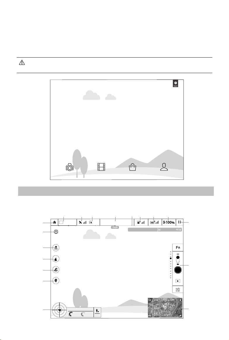
Camera
The Camera View contains a live HD video feed from the camera. You can also congure various
camera parameters here.
[18]
[17]
[16]
[15]
[14]
[13]
[12]
MODE
P-GPS
H: D:
39M 210M
V.S
[5]
[4][3][2][1]
Safe to Fly (GPS)
CL
1/320
ISO 100
H.S
M/S
232M
4.22.3
M/S
1.2M
[8][7][6]
4821
EV 0
JPEG
2015 DJI. All Rights Reserved.
©
[9]
[10]
[11]
45
Page 46

DJI MATRICE 100 User Manual
[1] Flight Mode
: The text next to this icon indicates the current ight mode.
Tap this icon to congure the MC (Main Controller) Settings, to change the ight limits and set the
gain values.
When using the DJI Pilot app for the rst time, the aircraft is in Beginner Mode. In this mode,
the ight altitude and ight distance are set to 30 m. Tap
[2] GPS Signal Strength
: Shows the current GPS signal strength. Green bars indicate adequate GPS strength.
[3] IOC Settings
CL: Displays the IOC settings when the aircraft has entered F-Mode. Tap this icon to view the
IOC menu and select the desired IOC mode.
[4] System Status
: Indicates the current aircraft system status and GPS signal strength.
[5] Battery Level Indicator
: Describes the battery level of the aircraft according to its immediate status. The colored
zones represent the various stages of battery level. When the battery level drops to a certain
stage, the system will prompt the user to take the appropriate action.
[6] Remote Controller Signal
: Shows the signal strength of the remote controller.
[7] HD Video Link Signal Strength
: Shows the signal strength of the HD video downlink between the aircraft and the remote
controller.
to exit Beginner Mode.
[8] Battery Level
: Shows the current battery level.
Tap this icon to view the battery information menu where you can set the battery warning
thresholds and view the battery log.
[9] General Settings
: Tap this icon to view General Settings where you can set the flight parameters, reset the
camera settings, enable the Quick Review function, adjust the Gimbal Roll value, and enable the
Flight Route display.
[10] Camera Operation Bar
Shutter and Recording Settings
: Tap this icon to enter various camera value settings including the Color mode, Video Size,
and Image Size.
Shutter
: Tap this button to take a single photo. Press and hold this button to switch between Single
Shot, Triple Shot and Timed Shot modes.
2015 DJI. All Rights Reserved.
46
©
Page 47

DJI MATRICE 100 User Manual
Record
: Tap once to start recording video, then tap again to stop recording. You can also press the
Video Recording Button on the remote controller.
Playback
: Tap this icon to play back photos and videos after they are captured.
Camera Settings
: Tap this icon to set the ISO, Shutter Speed and Exposure Value of the camera.
[11] Mini Map
Displays the ight path of the current ight. Tap the Mini Map to switch between Camera View
and Map View.
[12] Flight Telemetry
H: D:
39M 210M
V.S
H.S
M/S
232M
4.22.3
M/S
Flight Attitude and Radar Function:
The aircraft’s ight attitude is indicated by the target-like icon.
(1) The red arrow shows which direction the aircraft is facing.
(2) The ratio of the grey area to the blue area indicates the aircraft’s pitch.
(3) The horizontal level of the grey area indicates the aircraft’s roll angle.
Flight Parameters:
Altitude: Vertical distance from the Home Point.
Distance: Horizontal distance from the Home Point.
Vertical Speed: Movement speed across a vertical distance.
Horizontal Speed: Movement speed across a horizontal distance.
Aircraft Distance:
The horizontal distance between the aircraft and the operator.
[13] Home Point Settings
: Tap this icon to update the Home Point. You may set the aircraft takeoff location, the remote
controller’s current position, or the aircraft’s current position as the Home Point.
[14] Return-to-Home (RTH)
: Tap this icon to initiate the RTH procedure which will bring the aircraft back to the latest
Home Point.
2015 DJI. All Rights Reserved.
©
47
Page 48

DJI MATRICE 100 User Manual
[15] Gimbal Operation Mode
Refer to DJI Zenmuse X3 Gimbal with Camera under the Appendix (P73) for more information.
[16] Auto Takeoff/Landing
/ : Tap to initiate auto takeoff or landing.
[17] Livestream
: This icon indicates the current video feed is being broadcast live on YouTube. Ensure that
mobile data service is available on your mobile device.
[18] Back
: Tap this icon to return to the main menu.
Director
Director is an intelligent video editor built into the DJI Pilot app. After recording several video clips and
downloading them to your mobile device, go to Director on the home screen. You can then select a
template and a specied number of clips which are automatically combined to create a short lm that
can be shared immediately.
Store
Tap Store to visit the ofcial DJI Online Store to see the latest DJI products.
User Center
Review images and videos downloaded to your mobile device, view ight logs, and check your DJI
account status in the User Center. Use your registered DJI account to login into the User Center.
2015 DJI. All Rights Reserved.
48
©
Page 49

Using the PC Assistant
1. Download the DJI Driver and the DJI N1 Assistant installation les from the M100 download page.
2. Complete the installations for the DJI Driver and the DJI N1 Assistant.
(https://dev.dji.com/products/ying-platforms/matrice-100/downloads)
3. Turn on the remote controller, and then turn on the Intelligent Flight Battery in the aircraft. Connect the
M100 to the PC with a Micro-USB cable. Do not disconnect the cable until conguration is nished.
4. Run the DJI N1 Assistant software. Login with your DJI account, or create a new account. Observe
the indicators at the bottom of the screen. When a connection is established, the Connection Status
Indicator (on the left) will glow solid green and the Data Exchange Indicator (on the right) will blink blue.
Basic Page
1) API
If you are using the DJI SDK, select Enable API Control to allow the flight control system to
communicate with external devices such as an on-board computer. The external device will be able
to control the aircraft only if the Flight Mode Switch on the remote controller is toggled to F-Mode. For
information on setting the API parameters, read the related documents and manuals on the DJI SDK
page of the DJI Developer website (https://dev.dji.com/products/sdk).
2015 DJI. All Rights Reserved.
©
49
Page 50

DJI MATRICE 100 User Manual
API Control and the IOC function cannot be used at the same time. If you want to use API
Control, disable the IOC function rst.
The Enable API Control option is automatically disabled after rmware updates. Re-enable
this option if necessary.
2) Mounting
Fill in the coordinates of the GPS module relative to the aircraft’s geometric center (GC). The GC of the
aircraft can be approximated as the intersection of lines joining opposite motors, at the same level as
the propeller rotation plane. Note the negative and positive directions of the X, Y and Z axes illustrated
in the application. Leave the IMU coordinates as the default values.
Inaccurate coordinates or a wrong axis polarity may cause the aircraft to vibrate during
ight. If this happens, double check the conguration parameters.
The label on the GPS module should face upwards, and the arrow should point to the nose
of the aircraft.
Be sure to update the settings if you change the mounting positions of your aircraft’s
components.
2015 DJI. All Rights Reserved.
50
©
Page 51

DJI MATRICE 100 User Manual
Tools Page
Check the rmware version and click the hyperlink to update the rmware.
Update the rmware of the extra Intelligent Flight Battery as follows:
a. Turn off all Intelligent Flight Batteries.
b. Insert the battery that needs a rmware update into the battery compartment that is connected to
the ight controller.
c. Turn on the Intelligent Flight Batteries. Click the hyperlinks to update the rmware.
Update the remote controller rmware via the DJI Pilot app. Refer to Updating the Firmware (P64) for
details.
The remote controller may become unlinked from the aircraft after the rmware update. Re-
link the remote controller to the aircraft if necessary.
It is normal for the aircraft to make sounds or its LEDs to ash during the rmware update.
If you are using the DJI Zenmuse X3 Gimbal with Camera, update all rmware using the
rmware update package. Refer to Updating the Firmware (P64) for details.
2015 DJI. All Rights Reserved.
©
51
Page 52

DJI MATRICE 100 User Manual
Info Page
Change user account or view the software information on this page.
The versions of the aircraft’s firmware and the DJI N1 Assistant software should be
compatible when conguring the M100. It is recommended to update to the latest rmware
and software versions to avoid this issue.
Using the SDK
DJI Mobile API and Onboard API are supported by the M100. Users can use these APIs to develop
their own applications to monitor and control their aircraft. Visit the DJI SDK page on the DJI
Developer website (https://dev.dji.com/products/sdk) for information on using these APIs.
2015 DJI. All Rights Reserved.
52
©
Page 53

Flight
Once pre-ight preparation is complete, it is recommended to use the ight simulator to learn how to
y safely. Ensure that all ights are carried out in an open area.
Flight Environment
1. Do not use the aircraft in adverse weather conditions including raining, snowing, fog, and wind
speeds exceeding 10 m/s.
2. Only y in open areas. Tall buildings and steel structures may affect the accuracy of the compass
and the GPS signal.
3. Avoid ying near obstacles, crowds, high voltage power lines, trees and bodies of water.
4. Avoid ying in area with high levels of electromagnetism, including mobile phone base stations and
radio transmission towers.
5. Aircraft and battery performance is subject to environment factor such as air density and
temperature. Be very careful when ying over 14700 feet (4500 meters) above sea level as the
battery and aircraft performance may be reduced.
6. The M100 cannot operate in P-Mode within the Earth’s polar regions.
Flight Limits and No Fly Zones
Flight limits on height and distance can be set.
Unmanned aerial vehicle (UAV) operators should abide by the regulations from self-regulatory
organizations such as the ICAO (International Civil Aviation Organization), the FAA and their local
aviation authorities. For safety reasons, flight limits are enabled by default to help users use this
product safely and legally.
When operating in P-Mode, the height limit, distance limit and No Fly Zones work together to monitor
ight. In A-Mode, only the height limit prevents the aircraft from going above 120 meters.
Maximum Height and Radius Limits
Users can change the maximum height and radius limits in the DJI Pilot app. Once complete, your
M100 will y in a restricted cylinder that is determined by these settings. The tables below show the
details of these limits.
Max Height
Max Radius
Home Point
Height of aircraft
when powered on
2015 DJI. All Rights Reserved.
©
53
Page 54

DJI MATRICE 100 User Manual
GPS Signal is Strong Flashing Green
Flight Limits DJI Pilot App Aircraft Status Indicator
Max Height
Max Radius
Flight altitude must be
below the preset height.
Flight distance must be
within the max radius.
Warning: Height
limit reached.
Warning: Distance
limit reached.
None.
Flashes red rapidly when the
aircraft approaches the max radius
limit.
GPS Signal is Weak Flashing Yellow
Flight Limits DJI Pilot App Aircraft Status Indicator
Max Height
Flight height restricted to
under 120m.
Warning: Height limit reached. None.
Max Radius No limit
If you y out of bounds, you can still control the M100, but cannot y it further.
If the M100 loses GPS signal and flies out of the max radius but regains GPS signal
afterwards, it will y back within range automatically.
No Fly Zones
All No Fly Zones are listed on the DJI ofcial website at http://ysafe.dji.com/no-y. No Fly Zones are
divided into Airports and Restricted Areas. Airports include major airports and flying fields where
manned aircraft operate at low altitudes. Restricted Areas include borders between countries or
sensitive sites. The details of the No Fly Zones are explained below:
Airports (requires GPS):
Airports
1640
feet
66 feet
320 feet
1 mile
R2
R1
Altitude-Restricted Zone Warning ZoneNo Fly Zone
1. Airport No Fly Zones are comprised of a no y zone and an altitude-restricted zone. Each type of
zone encompasses a radius of a certain size.
2. R1 miles around the airport (depending on its shape and size) encompasses the no y zone, inside
of which takeoff and ight are prohibited.
2015 DJI. All Rights Reserved.
54
©
Page 55

DJI MATRICE 100 User Manual
Altitude-Restricted Zone Warning ZoneNo Fly Zone
R1
66 feet
1 mile
R2
Airports
3. From R1 to R1+1 miles around the airport, the ight altitude is limited at a 15 degree incline,
starting at 66 feet (20 meters) from the edge of airport and radiating outwards. The flight
altitude is limited to 1640 feet (500 meters) at R1+1 miles.
4. When the aircraft is within 320 feet (100 meters) of a no fly zone, a warning message will
appear in the DJI Pilot app.
Restricted Areas (requires GPS):
Restricted Areas
100m
R
Warning Zone Free ZoneNo Fly Zone
1. Restricted Areas do not have an altitude-restricted zone.
2. R miles around the Restricted Area (depending on the regulation) is a no y zone, inside of which
takeoff and ight are prohibited.
3. A Warning Zone is set on the perimeter of the Restricted Area. When the aircraft is within 0.062
miles (100 m) of the no y zone (inside the Warning Zone), a warning message will appear in the
DJI Pilot app.
2015 DJI. All Rights Reserved.
©
55
Page 56

DJI MATRICE 100 User Manual
GPS Signal is Strong Flashing Green
Zone Restrictions DJI Pilot App Warning
Warning: You are in a no y zone.
Takeoff prohibited.
Warning: You are in a no y zone.
Automatic landing has begun. (If the
aircraft is within R1)
Warning: You are in a restricted
zone. Descending to a safe altitude.
(If the aircraft is within R2 but
outside R1)
Warning: You are in a restricted
zone. Max ight height restricted
between 20 and 120 m. Fly
Cautiously.
Warning: You are approaching a
Restricted Area. Fly cautiously.
No Fly
Zone
Altitude-
Restricted
Zone
Warning
Zone
Free Zone
Motors will not start.
If the aircraft loses GPS
signal and enters the
restricted area but regains
GPS signal afterwards,
the aircraft will enter Semi-
Automatic Descent and
land itself.
If the aircraft loses GPS
signal and enters the
restricted area but regains
GPS signal afterwards, it will
descend to a safe altitude
and hover 15 feet below the
safe altitude.
No ight restrictions.
No ight restrictions. None. None.
Aircraft Status
Indicator
Flashing Red
Semi-Automatic Descent: All stick commands are available except the throttle stick command
during the descent and landing process. Motors will stop automatically after landing.
When ying in No Fly Zones, the Aircraft Status Indicator will ash red rapidly and continue
for 3 seconds, then switch to indicate the current ying status and continue for 5 seconds,
at which point it will switch back to ashing red rapidly.
For safety reasons, please do NOT y close to airports, highways, railway stations, railway
lines, city centers or other busy areas. Try to ensure the aircraft is visible at all times.
2015 DJI. All Rights Reserved.
56
©
Page 57

DJI MATRICE 100 User Manual
Pre-Flight Checklist
1. The remote controller, Intelligent Flight Battery, and your mobile device are fully charged.
2. Propellers are mounted correctly and rmly.
3. Motors start properly and are functioning as normal.
4. The DJI Pilot app is connected to the aircraft.
Flight Status Indicator
The M100 comes with Front LEDs, Rear LEDs and an Aircraft Status Indicator. The positions of these
LEDs are shown in the gure below:
Aircraft Status Indicator
Front LEDs
The Front and Rear LEDs show the orientation of the aircraft. The Front LED is red and the Rear LED is
green. The Aircraft Status Indicator indicates the status of the ight controller. Refer to the table below
for more information about the Aircraft Status Indicator:
Rear LEDs
Aircraft Status Indicator Description
Normal
Flashing Red, Green and Yellow Alternatively Power on and self-check
Flashing Green and Yellow Alternatively Aircraft warming up
Flashing Green Slowly Safe to Fly (P-Mode with GPS)
Flashing Yellow Slowly Safe to Fly (No GPS)
Warning
Flashing Yellow Rapidly Remote controller signal Lost
Flashing Red Slowly Low battery warning
Flashing Red Rapidly Critically low battery warning
Flashing Red Alternatively IMU error
—— Solid Red Critical error
Flashing Red and Yellow Alternatively Compass calibration required
2015 DJI. All Rights Reserved.
©
57
Page 58

DJI MATRICE 100 User Manual
Calibrating the Compass
IMPORTANT: Be sure to calibrate the compass for every new ight location. The compass is a very
sensitive instrument that requires regular calibration to ensure optimal ight performance. Abnormal
compass data due to a lack of calibration can lead to poor ight performance or even failure.
Do NOT calibrate your compass where there is a chance of strong magnetic interference,
such as magnetite quarries, parking structures, and underground steel reinforcements.
Do NOT carry ferromagnetic objects such as keys with you during calibration.
Do NOT calibrate besides massive metal objects.
Do NOT calibrate in an indoor space.
Calibration Procedures
Choose an open space to carry out the following procedures.
1. Ensure the compass is calibrated. If you did not calibrate the compass as part of your pre-ight
preparations, or if you have moved to a new location since the last calibration, tap the System
Status bar in the app and select Calibrate, then follow the on-screen instructions to calibrate the
aircraft step-by-step.
2. Hold the aircraft horizontally, and rotate it 360 degrees along the central axis. The Aircraft Status
Indicator will emit a solid green light.
3. Hold the aircraft vertically with its nose pointing downwards, and rotate it 360 degrees around its
central axis.
4. Recalibrate the compass if the Aircraft Status Indicator becomes solid red.
If the Aircraft Status Indicator ashes red and yellow alternatively after compass calibration,
move your aircraft to a different location to carry out the calibration.
Calibrate the compass after you launch the DJI Pilot app if you are prompted to do so.
When to Recalibrate
1. The compass data is abnormal, and the Aircraft Status Indicator is ashing red and yellow alternatively.
2015 DJI. All Rights Reserved.
58
©
Page 59
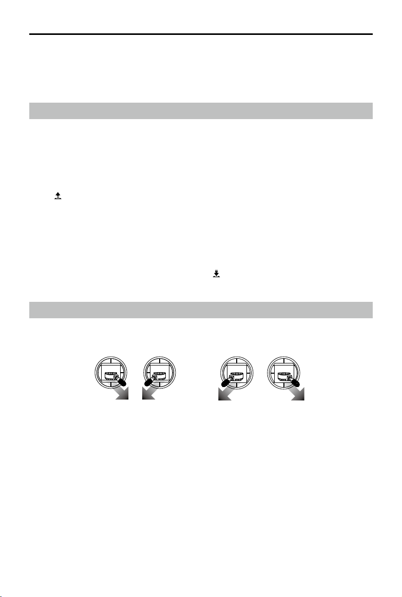
DJI MATRICE 100 User Manual
2. Flying in a new location, or a location that is different from your last ight.
3. The mechanical structure of the M100 is changed, i.e. the mounting position of the GPS module is
changed.
4. Severe drifting occurs in ight, i.e. the M100 has difculty ying in a straight line.
Auto Takeoff and Auto Landing
Auto Takeoff
Use Auto Takeoff to take off your aircraft automatically if the Aircraft Status Indicator is ashing green.
Follow the steps below to use Auto Takeoff:
1. Launch the DJI Pilot app and enter the Camera View.
2. Ensure that the aircraft is in P-Mode.
3. Go through the pre-ight checklist.
4. Tap and slide Conrm to take off.
5. The aircraft will take off and hover 1.2 meters above the ground.
Auto Landing
Use Auto Landing to land your aircraft automatically if the Aircraft Status Indicator is ashing green.
Follow the steps below to use Auto Landing:
1. Ensure that the aircraft is in P-Mode.
2. Check that the landing area is clear before tapping to land the aircraft.
3. The aircraft will begin to land automatically.
Starting and Stopping the Motors
The Combination Stick Command (CSC) listed below is used to start/stop the motors. Ensure you
perform the CSC in one continuous motion.
OR
Starting the Motors
Perform the CSC command. The motors will begin to speed at an idle speed, with the aircraft
remaining stationary.
Stopping the Motors
There are two methods to stop the motors.
Method 1: When the M100 has landed, push the throttle stick down, then perform the CSC command
to stop the motors. Release both sticks once the motors have stopped.
Method 2: When the aircraft has landed, push the throttle down and hold. The motors will stop after 3
seconds.
2015 DJI. All Rights Reserved.
©
59
Page 60

DJI MATRICE 100 User Manual
OR
Do NOT perform the CSC command when the aircraft is in mid-air.
Flight Test
Takeoff / Landing Procedures
1. Place the aircraft on an open, at ground with the battery indicator facing you.
2. Power on the remote controller and your mobile device, and then the Intelligent Flight Battery.
3. Launch the DJI Pilot app and enter Camera View.
4. Wait until the Aircraft Status Indicator ashes green. This means the Home Point is recorded and it
is safe to y. If it ashes yellow, the Home Point has not been recorded and you should not take off.
5. Push the throttle stick up slowly to take off or use Auto Takeoff.
6. To land, hover over a level surface and gently pull down on the throttle stick to descend slowly.
7. After landing, execute the CSC command or push the throttle stick down for 3 seconds until the
motors come to a stop.
8. Turn off the Intelligent Flight Battery, followed by the remote controller.
When the Aircraft Status Indicator flashes yellow rapidly during flight, the aircraft has
entered the Failsafe mode.
The Aircraft Status Indicator will ash red slowly for a Low Battery Level warning, and ash
red rapidly for a Critically Low Battery Level warning during ight.
2015 DJI. All Rights Reserved.
60
©
Page 61

Appendix
Product Specications
Structure
Diagonal Wheelbase 650 mm
Weight (with TB47D battery) 2355 g
Weight (with TB48D battery) 2431 g
Max Takeoff Weight 3400 g
Optional Accessories
Expansion Bay Weight 45 g
Battery Compartment Weight 160 g
Zenmuse X3 Gimbal with Camera Weight 247 g
Performance
Hovering Accuracy (P-Mode, with GPS) Vertical: 0.5 m, Horizontal: 2.5 m
Max Angular Velocity Pitch: 300°/s, Yaw: 150°/s
Max Pitch Angle 35°
Max Speed of Ascent 5 m/s
Max Speed of Descent 4 m/s
Max Wind Resistance 10 m/s
Max Speed
Hovering Time (with TB47D battery)
Hovering Time (with TB48D battery)
Hovering Time (with two TB47D batteries) No payload: 33 min
Hovering Time (with two TB48D batteries) No payload: 40 min
Hovering Time (with TB47D battery and Zenmuse X3) No payload: 19 min
Hovering Time (with TB48D battery and Zenmuse X3) No payload: 23 min
22 m/s (ATTI mode, no payload, no wind)
17 m/s (GPS mode, no payload, no wind)
No payload: 22 min; 500g payload: 17 min;
1kg payload: 13 min
No payload: 28 min; 500g payload: 20 min;
1kg payload: 16 min
* The hovering time is based on ying at 10m above sea level in a no-wind environment and landing
with 10% battery level.
2015 DJI. All Rights Reserved.
©
61
Page 62

DJI MATRICE 100 User Manual
Propulsion System
Motor Model DJI 3510
Propeller Model DJI 1345s
ESC Model DJI E SERIES 620D
Flight Control System
Model N1
Other
Operating Temperature -10 to 40 ℃
Remote Controller
Name C1
5.725~5.825 GHz
Operating Frequency
Transmission Distance 2 km
EIRP
Video Output USB, Mini-HDMI
Power Supply Built-in battery
Charger DJI approved charger
Dual Users Capability Master-and-Slave control
Mobile Device Holder Supports smartphones and tablets
Output Power 9 W
Operating Temperature -10 to 40 ℃
Storage Temperature
Charging Temperature 0 to 40 ℃
Battery 6000 mAh LiPo 2S
Max Tablet Width 170 mm
922.7MHz~927.7 MHz (Japan)
2.400~2.483 GHz (Lightbridge)
10dBm@900M
13dBm@5.8G
20dBm@2.4G
< 3 months: -20 to 45 ℃
> 3 months: 22 to 28 ℃
Charger
Model A14-100P1A
Voltage Output 26.3 V
Power Rating 100 W
Battery (Standard)
Name Intelligent Flight Battery
Model TB47D
Capacity 4500 mAh
Voltage 22.2 V
2015 DJI. All Rights Reserved.
62
©
Page 63

DJI MATRICE 100 User Manual
Type LiPo 6S High voltage battery
Energy 99.9 Wh
Net Weight 600 g
Operating Temperature -10 to 40 ℃
Storage Temperature
Charging Temperature 0 to 40 ℃
Max Charging Power 180 W
< 3 months: -20 to 45 ℃
> 3 months: 22 to 28 ℃
Battery (Optional)
Name Intelligent Flight Battery
Model TB48D
Capacity 5700 mAh
Voltage 22.8 V
Type LiPo 6S
Energy 129.96 Wh
Net Weight 676 g
Operating Temperature -10 to 40 ℃
Storage Temperature
Charging Temperature 0 to 40 ℃
Max Charging Power 180 W
< 3 months: -20 to 45 ℃
> 3 months: 22 to 28 ℃
Aircraft Status Indicator Description
Normal
Flashing Red, Green and Yellow Alternatively Power on and self-check
Flashing Green and Yellow Alternatively Aircraft warming up
Flashing Green Slowly Safe to Fly (P-Mode with GPS)
Flashing Yellow Slowly Safe to Fly (No GPS)
Warning
Flashing Yellow Rapidly Remote controller signal Lost
Flashing Red Slowly Low battery warning
Flashing Red Rapidly Critically low battery warning
Flashing Red Alternatively IMU error
—— Solid Red Critical error
Flashing Red and Yellow Alternatively Compass calibration required
2015 DJI. All Rights Reserved.
©
63
Page 64

DJI MATRICE 100 User Manual
Intelligent Orientation Control (IOC)
IOC allows users to lock the orientation of aircraft in different fashions. It has three working modes you
can choose in the DJI Pilot app. IOC only works in F-Mode, and users must toggle the ight mode
switch to F-Mode to activate IOC. The three work modes are:
Lock the current nose direction as the aircraft’s forward direction. The aircraft will move in
CL
the locked directions regardless of its orientation (yaw angle). Tap Reset IOC to reset the
Course Lock.
Record a Home Point, and push the Pitch stick up/down to control the distance of the
HL*
aircraft from the Home Point.
POI* Record a point of interest (POI). The aircraft’s nose always points towards the POI.
*The Home Lock (HL) and Point of Interest (POI) features are coming soon.
Prerequisites of IOC
Use IOC under the following conditions:
IOC Modes GPS Enabled GPS Signal Strength Flight Distance Limits
Course Lock No None None
Home Lock Yes
POI Yes
Aircraft
≥10 m
Aircraft
Home Point
5 m - 500 m
POI
Enabling IOC
Go to the DJI Pilot app > Camera View >
controller, toggle the Flight Mode Switch to F-Mode to use IOC.
F-Mode supports IOC, API Control and other functions, with IOC having the highest priority.
Disable IOC rst to use other functions.
> Advanced Settings > Toggle IOC. On the remote
Updating the Firmware
Updating the Aircraft and the Battery Firmware
Using the M100 without a Gimbal
If you are not using a gimbal, connect the aircraft to the DJI N1 Assistant to update the aircraft’s and
the battery’s rmware. Refer to Tool Page under Using the PC Assistant (P51) for details.
Using the M100 with the DJI Zenmuse X3 Gimbal with Camera
If you are using the DJI Zenmuse X3 Gimbal with Camera, follow the steps below to update the aircraft
and the battery.
2015 DJI. All Rights Reserved.
64
©
Page 65

DJI MATRICE 100 User Manual
Updating the Aircraft Firmware
Step 1- Check the Battery Level and Micro SD Card Storage
Ensure that the Intelligent Flight Battery has at least 50% power level and there is at least 100MB of
free space on the Micro SD card.
Step 2- Prepare the Firmware Update Package
1. Download the rmware update package from the DJI Developer website.
(https://dev.dji.com/products/ying-platforms/matrice-100/downloads)
2. Insert the Micro SD card into your PC. Extract all the downloaded les into the root directory of the
Micro SD card. While the M100 is powered off, remove the Micro SD card from your PC and insert
it into the Micro SD card slot on the gimbal.
Step 3- Update the Aircraft
1. Ensure the remote controller is powered off and then power on the aircraft. The rmware update
will begin automatically once the aircraft is powered on.
2. It will take approximately 25 minutes to complete the rmware update. The camera will sound a
short pulse of "D-D-D-D" beeping sound to indicate that the update is in progress, and sound a
“D —DD” beeping sound to indicate that the update has been completed successfully.
3. Check the update status by opening the .txt le that is automatically generated after the update.
You should see the text “result: successful” in the .txt le if the update is successful. Otherwise, try
updating the rmware again if you see the text “result: failed” in the text le or the gimbal sounds a
long beep sound.
Updating the Intelligent Flight Battery Firmware
The Intelligent Flight Battery is updated during the aircraft rmware update. It is recommended to
keep the update package les on your Micro SD card. The update will start automatically once the
aircraft is powered on.
Update the rmware of an extra Intelligent Flight Battery as follows:
1. Power off all Intelligent Flight Batteries.
2. Insert the battery that needs the rmware update into the battery compartment connected to the
ight controller.
3. Power on the Intelligent Flight Battery in the battery compartment. The update will start
automatically.
Do NOT perform the rmware update while the aircraft is still ying in the air. Only carry out the
rmware update when the aircraft is on the ground.
The remote controller may become unlinked from the aircraft after the rmware update. Re-
link the remote controller and aircraft if necessary.
Conrm the update result according to the gimbal sounds. It is normal for the aircraft to
make sounds or its LEDs to ash during the update process.
Ensure that there is only one rmware package le stored on your Micro SD card.
Only storage devices that are formatted with FAT32 and exFAT le systems are supported.
2015 DJI. All Rights Reserved.
©
65
Page 66

DJI MATRICE 100 User Manual
Updating the Remote Controller Firmware
The System Status bar in Camera View of the DJI Pilot app will ash several times if a rmware update
is available. Follow these steps to update the rmware via the DJI Pilot app.
Step 1- Check the Following
1. The remote controller has at least 50% battery level
2. Your mobile device is able to access the internet
3. There is at least 30 MB of free space on your mobile device
Step 2- Download and Update the Firmware
Go to the DJI Pilot app > Camera View > System Status bar > Overall Status. Tap Download rmware
to download and update the rmware.
If the firmware update fails, check the connection between the remote controller and your mobile
device, then retry the update. Contact DJI Support if you still have problems. (http://www.dji.com/
support)
Do NOT perform the rmware update while the aircraft is ying in the air. Only carry out the
rmware update when the aircraft is on the ground.
The remote controller may become unlinked from the aircraft after the rmware update. Relink
the remote controller and aircraft if necessary.
Ensure the internet connection of your mobile device is stable when downloading the rmware
package.
2015 DJI. All Rights Reserved.
66
©
Page 67

DJI MATRICE 100 User Manual
Component Dimensions
Use the dimensions below to help you customize your M100 platform (all units in mm).
Aircraft
3548
39
188
218
650
701
2015 DJI. All Rights Reserved.
©
67
Page 68

DJI MATRICE 100 User Manual
511
806
996
Remote Controller
2015 DJI. All Rights Reserved.
68
©
105
71
Page 69

Mounting Rails
Expansion Bay Base Plate
DJI MATRICE 100 User Manual
10 10
6010 10
101
106
111
100
80
59.40
25.46
1.50
24
2.50
60
25.46
59.40
20
40
2.50
24 16 24
80
2.50
80
60
100
4
2015 DJI. All Rights Reserved.
©
69
Page 70

DJI MATRICE 100 User Manual
Gimbal Mounting Plate
Battery Compartment
86
80
74
39
30
23
32
Ø 2
80
Ø 8.60
27.50
58
22.50
106
64
70
DJI Zenmuse X3 Gimbal with Camera
Camera
Camera Prole
The X3 gimbal camera can record up to 4K 4096x2160p video at 24 fps, and capture 12-megapixel
images. It features a 1/2.3” Sony EXMOR CMOS image sensor. Preview of the camera’s POV in the
DJI Pilot app before shooting images and video. Have extra options to shoot stills in burst mode or
self-timer mode, and export video in either MOV or MP4 format.
Camera Micro SD Card Slot
To store your photos and videos, plug in the Micro SD card
into the Micro SD card slot on the gimbal before powering on
the M100. The camera supports a single Micro SD card of
up to 64GB. A UHS-1 type Micro SD card is recommended
because of its fast read and write capability, allowing you to
store high-resolution video les.
Do NOT remove the Micro SD card from the gimbal
when it is powered on.
2015 DJI. All Rights Reserved.
70
©
Page 71

DJI MATRICE 100 User Manual
Camera Data Port
Power on the M100 and then connect a USB cable to the Camera Data Port to download photos or
videos from the camera to your PC.
Power on the aircraft before downloading the les.
Camera Operation
Use the Shutter and Record button on the remote controller to shoot images or the videos through the
DJI Pilot app. For more information on how to use these buttons, refer to Controlling the Camera (P33).
ND Filter
Attach an ND lter to the front of the camera to reduce over exposure and the ‘jello’ effect.
Gimbal
Gimbal Prole
The 3-axis gimbal provides a steady platform for the camera, allowing you to capture stable video and
images. The gimbal can tilt the camera up to 120 degrees and rotate 320 degrees.
+
30°
-90°
0°
-320°
+
320°
2015 DJI. All Rights Reserved.
©
71
Page 72

DJI MATRICE 100 User Manual
Under the default settings, turn the gimbal dial on the remote controller to tilt the camera. Note that
you cannot simultaneously tilt and pan the camera in the Single Remote Controller mode. Enable the
Master-and-Slave mode in the DJI Pilot app and set a second remote controller to Slave if you wish to
tilt and pan the camera together.
Gimbal Dial Settings
Follow the instructions below to use the gimbal dial to tilt/pan the camera:
1. Power on the aircraft and the remote controller.
2. Go to the DJI Pilot app > Camera View > Tap
> Tap RC Control Settings.
3. Set the customizable button C1 or C2 as the Gimbal Pitch/Yaw.
RC Control Settings
RC Calibration
Stick Mode
Default stick mode is Mode 2, changing stick modes alters the way the aircraft is controlled.
Do not change unless familiar with your new mode.
Gimbal Pitch/YawC1 C2 Reset gimbal yaw
You can customize the C1 and C2 buttons on the back
of the remote controller.
Linking RC
Press the C1 or C2 button to switch between pitch mode and yaw mode. Use the gimbal dial to
control the tilt/pan motion of the camera.
Using the DJI Pilot App to Control the Gimbal
Follow the steps below to use the DJI Pilot app to control the gimbal’s pitch/yaw motion:
1. Go to the DJI Pilot app > Camera View.
2. Tap and hold on the screen until a blue circle appears.
3. Move your nger to control the gimbal’s pitch/yaw motion.
MODE
2015 DJI. All Rights Reserved.
72
©
P-GPS
H: D:
39M 210M
V.S
H.S
M/S
4.22.3
Safe to Fly (GPS)
CL
232M
M/S
ISO 100
4821
1/320
JPEG
EV 0
Page 73

DJI MATRICE 100 User Manual
Gimbal Operation Modes
Switch between the three operation modes in Camera View in the DJI Pilot app. Note that your mobile
device must be connected to the remote controller for changes to take effect. Refer to the table below
for details:
Pitch Yaw
The gimbal’s orientation is aligned with the aircraft’s nose. One
Follow Mode
user alone can control the pitch motion of the gimbal, but a second
operator is required to control the yaw motion using a second remote
controller.
FPV Mode
The Gimbal will lock to the movement of the aircraft to provide a FirstPerson-View ying experience.
The Gimbal’s motion is independent of the aircraft’s orientation. One
Free Mode
user alone can control the pitch motion of the gimbal, but a second
user is required to control the yaw motion using a second remote
controller.
Re-alignment
Re-align the yaw angle of the gimbal with that of the aircraft. The pitch
angle remains unchanged during the re-alignment.
A gimbal motor error may occur if the gimbal is placed on an uneven ground because
of impact with ground objects. Be sure to take off from a at, open ground to protect the
gimbal from impact.
Flying in heavy fog or inside clouds may make the gimbal wet, leading to a temporary
failure. The gimbal will recover when it dries out.
2015 DJI. All Rights Reserved.
©
73
Page 74

DJI MATRICE 100 User Manual
Specications
Gimbal
Model Zenmuse X3
Power Output (Camera Attached) Static: 9 W; In Motion: 11 W
Operating Current Static: 750 mA; In Motion: 900 mA
Angular Vibration ±0.03°
Mounting Detachable
Controllable Range Pitch: -90° to +30°; Yaw: ±320°
Mechanical Range Pitch: -125° to +45°; Yaw: ±330°
Controllable Speed Pitch: 120°/s; Yaw: 180°/s
Camera
Name X3
Model FC350
Total Pixels 12.76 M
Effective Pixels 12.4 M
Max Image Size 4000 x 3000
ISO 100-3200 (Video); 100-1600 (Photo)
Shutter 8 to 1/8000 s
FOV (Field Of View) 94°
CMOS Sony EXMOR 1/2.3”
20 mm (35 mm format equivalent), f/2.8
Lens
Still Photography Modes
Video Recording Modes
Video Storage Bitrate 60 Mbps
Supported File Formats
Supported SD Cards
Operating Temperature -10 to 40 ℃
9 elements in 9 groups
Anti-distortion
Single shot
Burst mode: 3/5/7 frames
Auto Exposure Bracketing (AEB): 3/5 frames at ±0.7EV
Timed shot
UHD (4K): 4096x2160p 24/25, 3840x2160p 24/25/30
FHD: 1920x1080p 24/25/30/48/50/60
HD: 1280x720p 24/25/30/48/50/60
FAT32/exFAT
Image: JPEG, DNG
Video: MP4/MOV (MPEG-4 AVC/H.264)
Micro SD
Max capacity: 64 GB; Class 10 or UHS-1 rating required
2015 DJI. All Rights Reserved.
74
©
Page 75

DJI MATRICE 100 User Manual
DJI Guidance System Mounting Warning
1. If you mount the Guidance Sensors directly under the battery compartment, disconnect the cable
of the rear facing Guidance Sensor before accessing the Intelligent Flight Battery.
2. If you mount the side Guidance Sensors above the center frame, ensure they are mounted at
least 4 cm above the center frame, so that the propellers will not obstruct them. Be sure to mount
the down facing Guidance Sensor under the aircraft. Finally, mount the GPS mount on top of the
expansion bay using two M3x8 screws.
>4cm
3. If you are using the DJI Zenmuse X3 Gimbal with Camera and the DJI Guidance system together,
be sure to mount the side Guidance Sensors above the center frame, otherwise you will be unable
to mount the front facing Guidance Sensor.
2015 DJI. All Rights Reserved.
©
75
Page 76

Compliance Information
FCC Warning Message
Any Changes or modications not expressly approved by the party responsible for compliance could
void the user’s authority to operate the equipment.
This device complies with part 15 of the FCC Rules. Operation is subject to the following two
conditions: (1) This device may not cause harmful interference, and (2) this device must accept any
interference received, including interference that may cause undesired operation.
FCC Radiation Exposure Statement:
This equipment complies with FCC radiation exposure limits set forth for an uncontrolled environment.
This equipment should be installed and operated with minimum distance 20cm between the radiator &
your body. This transmitter must not be co-located or operating in conjunction with any other antenna or
transmitter.
Note: This equipment has been tested and found to comply with the limits for a Class B digital device,
pursuant to part 15 of the FCC Rules. These limits are designed to provide reasonable protection
against harmful interference in a residential installation. This equipment generates uses and can
radiate radio frequency energy and, if not installed and used in accordance with the instructions, may
cause harmful interference to radio communications. However, there is no guarantee that interference
will not occur in a particular installation. If this equipment does cause harmful interference to radio
or television reception, which can be determined by turning the equipment off and on, the user is
encouraged to try to correct the interference by one or more of the following measures:
Reorient or relocate the receiving antenna.
Increase the separation between the equipment and receiver.
Connect the equipment into an outlet on a circuit different from that to which the receiver is
connected.
Consult the dealer or an experienced radio/TV technician for help.
IC RSS Warning
This device complies with Industry Canada licence-exempt RSS standard (s). Operation is subject
to the following two conditions: (1) this device may not cause interference, and (2) this device must
accept any interference, including interference that may cause undesired operation of the device.
Le présent appareil est conforme aux CNR d'Industrie Canada applicables aux appareils radio
exempts de licence.
L'exploitation est autorisée aux deux conditions suivantes:
(1) l'appareil ne doit pas produire de brouillage, et
(2) l'utilisateur de l'appareil doit accepter tout brouillage radioélectrique subi, même si le brouillage
est susceptible d'en compromettre le fonctionnement.
IC Radiation Exposure Statement:
This equipment complies with IC RF radiation exposure limits set forth for an uncontrolled environment.
This transmitter must not be co-located or operating in conjunction with any other antenna or
transmitter.
This equipment should be installed and operated with minimum distance 20cm between the radiator
& your body.
2015 DJI. All Rights Reserved.
76
©
Page 77

DJI MATRICE 100 User Manual
Any Changes or modications not expressly approved by the party responsible for compliance could
void the user’s authority to operate the equipment.
KCC Warning Message
“해당무선설비는 운용 중 전파혼신 가능성이 있으므로 인명안전과 관련된 서비스는 할 수 없습니다 .”
“해당 무선설비는 운용 중 전파혼신 가능성이 있음”
인증받은자의 상호 : SZ DJI TECHNOLOGY CO., LTD
제품명 / 모델명 : 특정소출력무선기기 ( 무선데이터통신시스템용무선기기 )/M100
제조자 및 제조국가 : SZ DJI TECHNOLOGY CO., LTD
제조년월 : 2015.05
인증번호 : MSIP-CRM-dji-TP1406
해당 무선설비는 전파혼신 가능 성이 있으므로 인명안전과 관련된 서비스는 할 수 없음
NCC Warning Message
Administrative Regulations on Low Power Radio Waves Radiated Devices warning:
Article 12
Without permission granted by the NCC, any company, enterprise, or user is not allowed to change
frequency, enhance transmitting power or alter original characteristic as well as performance to an
approved low power radio-frequency devices.
Article 14
The low power radio-frequency devices shall not influence aircraft security and interfere legal
communications; If found, the user shall cease operating immediately until no interference is achieved.
The said legal communications means radio communications is operated in compliance with the
Telecommunications Act.
The low power radio-frequency devices must be susceptible with the interference from legal
communications or ISM radio wave radiated devices.
2015 DJI. All Rights Reserved.
©
77
Page 78

This content is subject to change.
Download the latest version from
https://dev.dji.com/products/ying-platforms/matrice-100
If you have any questions about this document, please contact DJI by
sending a message to
2015 DJI. All Rights Reserved.
©
DocSupport@dji.com
.
 Loading...