

Page 1
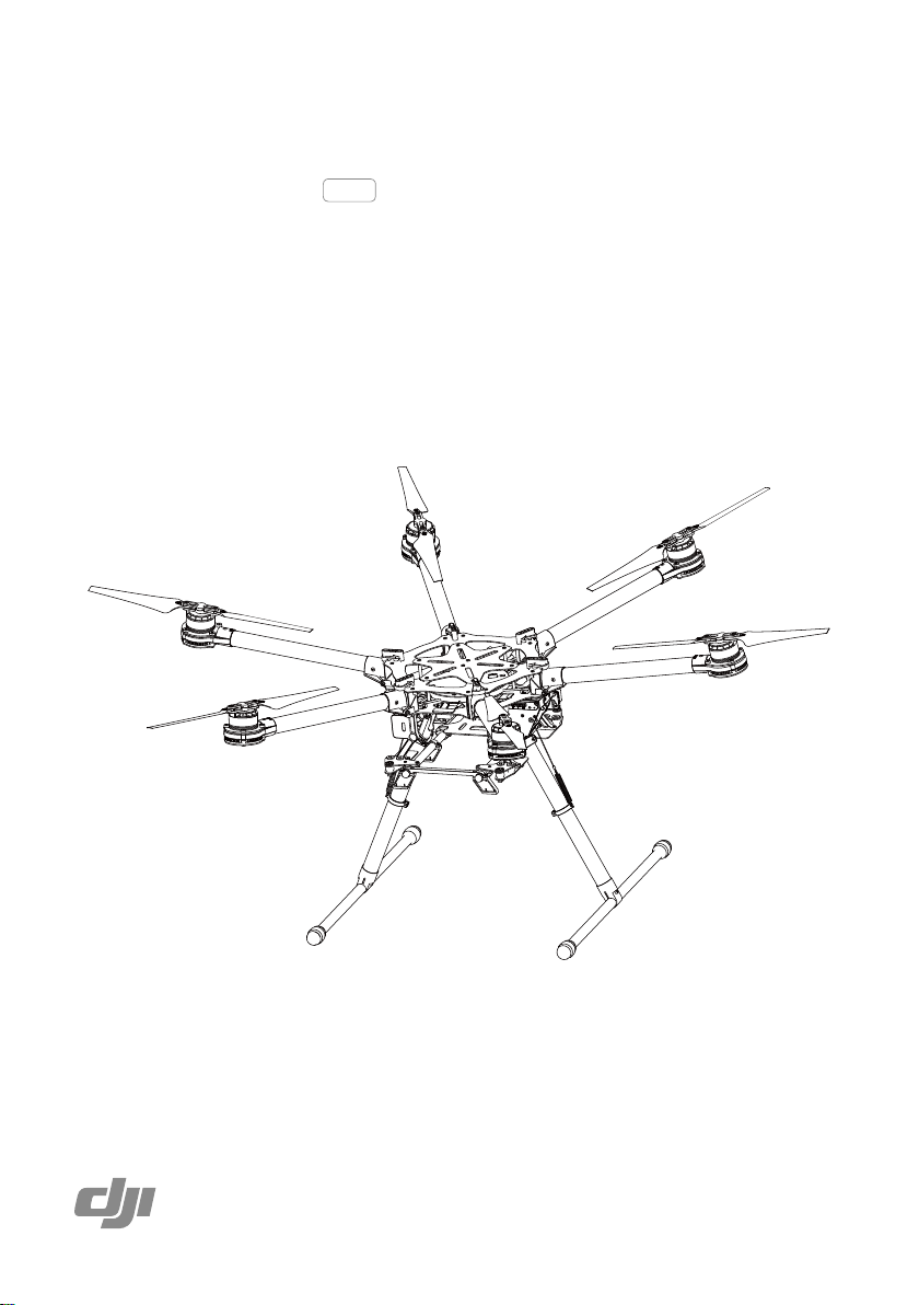
Spreading Wings S900
User Manual
2014.08
V1.0
Page 2
Spreading Wings S900
User Manual
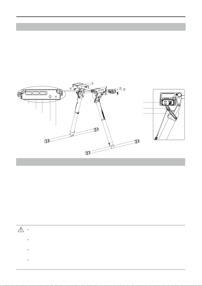
Remounting the Landing Gear Servo
Remounting servos is not recommended as they are pre-installed.
Instructions
1. Connect the left servo cable to the “L” port of the landing gear control board.
2. Connect the right servo cable to the “R” port of the landing gear control board.
3. Press the SET button using a pin then power on. You will see a yellow LED beside the SET button ashing
quickly. Wait as servos complete position initialization.
4. Make sure the arm connecting to the servo is parallel to the link as shown in the following diagram.
5. Assemble the left and right servos to the left (between M3, M4) and the right (between M5, M6) parts of the
landing gear. Power off.
IN
R
L
To right servo
To left servo
To receive channel
(To F1 port if use A2)
Connecting arm
SET Button
LED
Servo
Link
After Installation
Recalibrating Servo Travel
Instructions
1. Keep your hands away from all moving parts.
2. Ensure the [R], [L] and [IN] connections are correct.
3. Keep the whole aircraft off of the ground during calibration, as landing gear will move.
4. Press and hold the SET button using a pin while powering on, then release. An LED will flash yellow
quickly. Press the SET button again. Auto calibration will begin and the LED will ash yellow slowly. DO
NOT obstruct any moving parts during auto calibration.
5. During calibration, the left landing gear will raise and lower, followed by the right landing gear.
6. After calibration, both the left and right landing gears will be lowered and the LED will display a solid green
light. This indicates that the landing gear is working properly.
If the LED is solid yellow after calibration, a problem has occurred. Carry out the instructions in
“Remounting the Landing Gear Servo” then try again.
Avoid obstructions during calibration. If the landing gear was obstructed, recalibration will be
required, per the above steps.
If the [R] and [L] servo cables are reversed, travel will not be measured correctly. Fix the
connections and recalibrate the landing gear using the above steps.
Landing gear travel has been pre-calibrated. Mechanical adjustment of the gear travel is not
recommended.
2014 DJI. All Rights Reserved.
26
©
Page 3
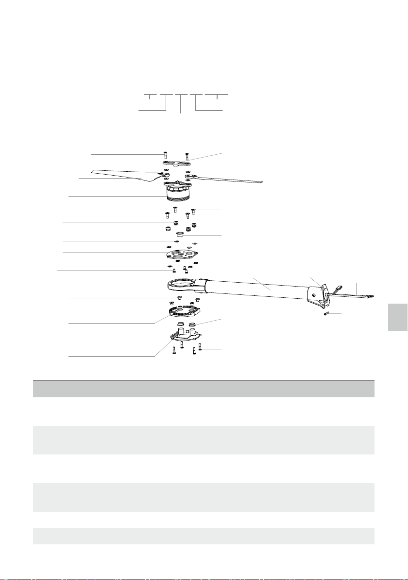
Part List
If you require a replacement part, locate the part that you wish to replace in the following tables. Then order
the package that comes with the specied part. The numbering of the part is dened as follow:
01-Frame Arm 02-Center Frame
03-Landing Gear
Frame Arm
M3x12.3 (hexagan)
S9012501CCW/
S9012502CW
S9012101B/
S9012201R
S9010801
S9010802
S9011001
M3x4.5
S9012902/
S9013002/
S9013102/
S9013202
S9012901/
S9013001/
S9013101/
S9013201
S9012301R/
S9012401G
S900
;
S9020101CCW
;
Package No.
CW as clockwise CCW as counter clock
; ; ;
wise B as Balck R as Red G as Green
Package Part No.
S9012102B/
S9012202R
S9012503
M3x10.3
S9012903/
S9013003/
S9013103/
S9013203
S9010401CCWB/
S9010501CCWR/
S9010601CWB/
S9010701CWR
S9012302/
S9012402
M3x12.3 (cheese)
;
S9010402/
S9010502/
S9010602/
S9010702
S9010403/
S9010503/
S9010603/
S9010703
S9010404/
S9010504/
S9010604/
S9010704
Part List
Package No. Name Part No.
4
5
6 S900 Frame Arm CW - Black S9010601CWB, S9010602, S9010603,
7 S900 Frame Arm CW – Red S9010701CWR, S9010702, S9010703,
8 S900 Motor Damping Unit S9010801, S9010802, M3x10.3
10 S900 Motor Mount Carbon Board S9011001, M3x4.5
S900 Frame Arm CCW - Black S9010401CCWB, S9010402, S9010403,
S9010404, M3x12.3 (cheese)
S900 Frame Arm CCW - Red S9010501CCWR, S9010502, S9010503,
S9010504, M3x12.3 (cheese)
S9010604, M3x12.3 (cheese)
S9010704, M3x12.3 (cheese)
2014 DJI. All Rights Reserved.
©
27
Page 4

Spreading Wings S900
User Manual
21 S900 4114 Motor with black Prop cover S9012101B, S9012102B, M3x4.5
22 S900 4114 Motor with red Prop cover S9012201R, S9012202R, M3x4.5
23 S900 ESC with Red LED S9012301R, S9012302, M3x12.3
(cheese)
24 S900 ESC with Green LED S9012401G, S9012402, M3x12.3
(cheese)
25 S900 Propeller Pack S9012501CCW, S9012502CW,
S9012503, M3x12.3 (hexagan)
Center Frame
S9020301
M2.5x8 (cheese)
S9021502
S9021503/
S9032703
Part List
M3x6.5
S9021501
S9020901
S9021201L
S9021203/
S9021101
S9021401
2014 DJI. All Rights Reserved.
28
©
S9020302
M3x8 (self-tapping)
S9021202R
M2.5x8 (cheese)
Page 5

Spreading Wings S900
User Manual
Package No. Name Part No.
3
9
12 S900 Arm Mounting Bracket S021201L, S021202R, S021203, M3x6.5
14 S900 Center Frame Bottom Board S9021401, M3x4.5 (cheese), M3x8 (self-
15 S900 Center Frame Top Board S9021501, S9021502, S9021503, M3x6.5,
11 S900 Frame Arm Mounting Steel Shaft S9021101
S900 Lock Knob S9020301, S9020302, M3x8 (self-tapping)
S900 Center Frame Support Pillar S9020901, M2.5x8 (cheese)
tapping), M3x6.5, M3x5.5
M2.5x8 (cheese)
Landing Gear
M3x4.5
S9031902
S9031814
S9031815
M3x6.5
S9031901
M2.5x13
S9031604/
S9033306
S9031602/
S9033303
S9033301
S9033302
S9031603/
S9033305
S9031601/
S9033304
S9031605/
S9033307
M2.5x5
M2.5x8 (cheese)
S9033308
S9033309
S9033310
S9033311
S9033312
S9031713/
S9031813
M2.5x8 (socket cap)
S9032601
S9032602
S9032603
M3x22 (socket cap)
S9032604
M2.5x10 (socket cap)
S9032605
M2.5x8 (socket cap)
Caution:(1) Parts within the dotted box are mirrored against each other.
Except for S9031814 and S9031815.
S9031808
S9031809
M1.6x5
S9031810
S9031811
(1)
S9031812
S9031712
S9031903
S9031904
S9031905
S9031701
S9030201
S9033313
S9033314
S9031801
S9031802
S9031803
S9031804
S9031805
M2.5x8(cheese)
S9031806
S9031807
S9032001
S9032002
M3x6.5
Part List
M3x8
M3x6.8
2014 DJI. All Rights Reserved.
©
29
Page 6

Spreading Wings S900
User Manual
Package No. Name Part No.
16
17
18 S900 Retractable
19 S900 Gimbal
20 S900 Landing Skid S9032001, S9032002
26 S900 Landing Skid
2 S900 Battery Tray S9030201
Part List
33 S900 Gimbal
S900 Gimbal
Damping Bracket
S900 Retractable
Module (Right)
Module (Left)
Damping
Connecting
Brackets
Leg
Mounting
Accessories
S9031601, S9031602, S9031603, S9031604, S9031605,
M2.5x5, M2.5x13
S9031701, S9031702, S9031703, S9031704, S9031705,
S9031706, S9031707, S9031708, S9031709, S9031710,
S9031711, S9031712, S0031713, M1.6x5, M2.5x10 (socket
cap), M2.5x8 (cheese), M2.5x5, M3x8, M3x4.5, M3x6.8
S9031801, S9031802, S9031803, S9031804, S9031805,
S9031806, S9031807, S9031808, S9031809, S9031810,
S9031811, S9031812, S9031813, S9031814, S9031815,
M1.6x5, M2.5x10 (socket cap), M2.5x8 (cheese), M2.5x5,
M3x8, M3x4.5, M3x6.8
S9031901, S9031902, S9031903, S9031904, S9031905,
M2.5x5, M3x6.5
S9032601, S9032602, S9032603, S9032604, S9032605,
M2.5x8 (socket cap), M3x22 (socket cap)
S9033301, S9033302, S9033303, S9033304, S9033305,
S9033306, S9033307, S9033308, S9033309, S9033310,
S9033311, S9033312, S9033313, S9033314, M2.5x5,
M2.5x13, M2.5x8 (cheese)
Miscellaneous
2014 DJI. All Rights Reserved.
30
©
S9032701
S9032702
S9020103
S9020201 S9020202
S9020104
Page 7

Spreading Wings S900
User Manual
Package No. Name Part No.
13
29 S900 Complete Arm
30 S900 Complete Arm
31 S900 Complete Arm
32 S900 Complete Arm
27 S900 GPS Holder
28 S900 Screw Pack Assorted screws
1 S900 Power Cord Plug S9020101, S9020102, S9020103, S9020104
S900 Center Frame Package 3, 9, 12, 14, 15
Package 7, 8, 10, 11, 22, 23, 25, S9012901, S9012902,
[CW-RED]
[CW-Green]
[CCW-RED]
[CCW-Green]
S9012903
Package 6, 8, 10, 11, 21, 24, 25, S9013001, S9013002,
S9013003
Package 5, 8, 10, 11, 22, 23, 25, S9013101, S9013102,
S9013103
Package 4, 8, 10, 11, 21, 24, 25, S9013201, S9013202,
S9013203
S9032701, S9032702, S9032703,
M2.5x8 (cheese)
The FCC Certication Requirements
This equipment has been tested and found to comply with the limits for a Class A digital device, pursuant
to part 15 of the FCC Rules. These limits are designed to provide reasonable protection against harmful
interference when the equipment is operated in a commercial environment. This equipment generates, uses,
and can radiate radio frequency energy and, if not installed and used in accordance with the instruction
manual, may cause harmful interference to radio communications. Operation of this equipment in a residential
area is likely to cause harmful interference in which case the user will be required to correct the interference
at his own expense.
The FCC Certication Requirements
2014 DJI. All Rights Reserved.
©
31
Page 8

User manual is subject to change without prior notice.
You may visit DJI ofcal website to obtain the latest version of user manual.
http://www.dji.com/product/spreading-wings-s900
2014 DJI. All Rights Reserved.
©
 Loading...