

Page 1
Aeroscope
AS-F1800
User Manual
2020.10
V2.0
Page 2

Page 3

Contents
Disclaimer and Warning
Product Prole
Introduction
IntheBox
Overview
Indicators
Function Descriptions
BasicFunctions
Features
OperationandMaintenance
Installation
LightningProtection
Step-by-StepInstallationGuide
ImportingCertificates
PowerCableUsage
Specications
Compliance Information
2
2
2
3
3
4
6
6
6
7
8
8
8
11
11
15
16
2018 DJI All Rights Reserved.
©
1
Page 4

Disclaimer and Warning
AeroScope is a comprehensive drone detection platform that rapidly identifies UAV
communication links, gathering information such as ight status, paths, and other information in
real-time (“Monitoring Data”). Monitoring Data stream helps users make an informed response
as soon as possible. Please note that Monitoring Data does not involve personal data of DJI
drone users. (Personal data is any information relating to an identied or identiable natural
person.) Unless pursuant to the requirement or request of any governmental or regulatory
agency or court or tribunal of competent jurisdiction to the extent such disclosure is required
by any valid laws, regulations, court orders or rules of relevant stock exchange, DJI will not
disclose any personal data that DJI collect through DJI Products and Services to third parties.
As an AeroScope’s end user, you represent and warrant that (a) you are the eligible user of
AeroScope. Examples of eligible users would be public safety organizations, law enforcement
agencies, government agencies, regulatory bodies, and owners or operators of airports, power
plants, and prisons; and (b) you will use AeroScope for monitoring public safety purpose only
(“Purpose”); and (c) you will comply with any applicable laws concerning the use of AeroScope
within the jurisdiction(s) of operation; and (d) you are solely responsible for the conducts of
anyone that use AeroScope through your account (“Authorized User”), which may include your
employees, consultants or contractors, or the employees, consultants or contractors of your
afliates, which are companies or entities that you own, that own you, or that have the same
owner or corporate parent as you.
You acknowledge and agree that (a) DJI do not help you comply with any laws, rules, or
regulations that may apply to your use of AeroScope, which is solely your responsibility; and
(b) DJI shall not be liable for the authenticity of you; and (c) DJI will not be liable for any loss
or damage you may cause; and (d) you will defend, indemnify, and hold harmless DJI, its
afliates, and its or their directors, ofcers, employees, agents, shareholders, successors and
assigns from and against all claims, losses, damages, penalties, liability, and cost, including
reasonable legal fees, of any kind or nature that are incurred in connection with or arising out
of a third-party claim relating to, or arising from your breach of Purpose.
PLEASE NOTE THAT IF YOU DO NOT DISPUTE THIS DISCLAIMER IN WRITING BEFORE
YOU USE AREOSCOPE, YOU ARE DEEMED TO HAVE ACCEPTED THE ENTIRE CONTENTS
OF THIS DISCLAIMER AND ARE SOLELY RESPONSIBLE FOR THE CONSEQUENCES OF
BREACH OF THIS DISCLAIMER.
Product Prole
Introduction
AEROSCOPETM detects UAVs ying within a particular surveillance area. Aeroscope receives
UAV broadcast information of various formats, and then sends the information to the data
processing platform via Ethernet or a 2G, 3G, or 4G wireless network card. The receiver and
antenna can be congured in a number of different ways. Also, Aeroscope has integrated
GPS, so users can see where the unit is on a map. And it
testing) functionality for regularly timed self-tests and remote self-tests, as well as accurate
environmental spectrum detection.
[1]
Aeroscope should be used with the DJI Background Management System (sold separately).
2018 DJI All Rights Reserved.
©
2
[1]
offers BIST (built-in self-
Page 5
Aeroscope AS-F1800
In the Box
Aeroscope Processor ×1 Female Power Connector ×1
[2]
Dongle
×1 RJ45 Connector ×1
Power Cable ×1 RJ45 Waterproof Case ×1
Processor Mounting Bracket A ×2 Screw Set ×1
Processor Mounting Bracket B ×2
Processor GND Cable ×1
Pin ×5
[2]
Only the waterproof dongle case is included in the North American version. The actual dongle must be
purchased separately.
Screw M80 ×100 (4 pcs)
Screw Nut M80 (4 pcs)
Washer M80 (4 pcs)
Screw M60 ×18 (4 pcs)
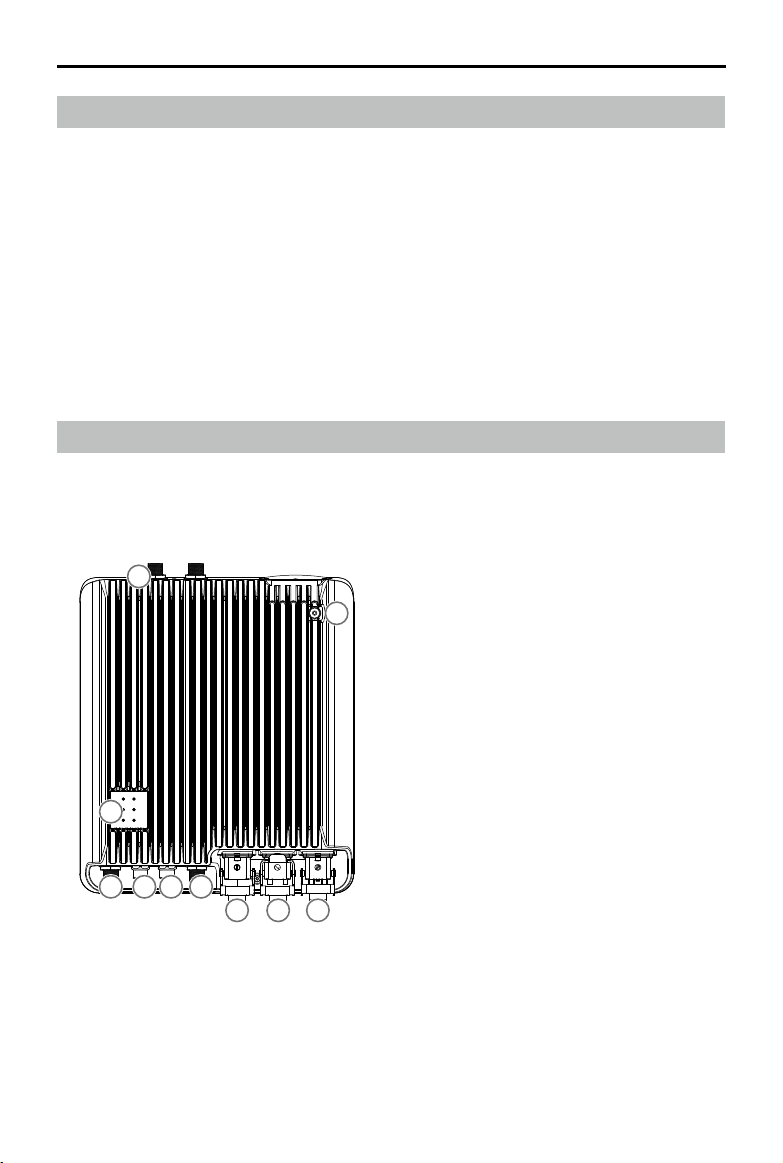
Overview
1. Antenna Ports
[3]
Connected to the antennas with the
ANT3ANT2
1
antenna cables.
2. Power Port
Connected to a 220V AC power outlet.
3. USB Port
Connected to a wireless network card or
a monitor.
4. Ethernet Port
Connected to a computer.
5. CAN Extension Port
Used for system debugging.
6. UART Extension Port
7
Used for system debugging.
7. Indicators
Six LEDs that indicate the status of each
1 1
586
ANT0 ANT1
234
module.
8. GND Connector
Connected to the metal bracket of the
mounting device.
[3]
The antenna ports (ANT0, ANT1, ANT2, ANT3) may be used during spectrum analysis. Make sure to
select the right one.
2018 DJI All Rights Reserved.
©
3
Page 6
Aeroscope AS-F1800
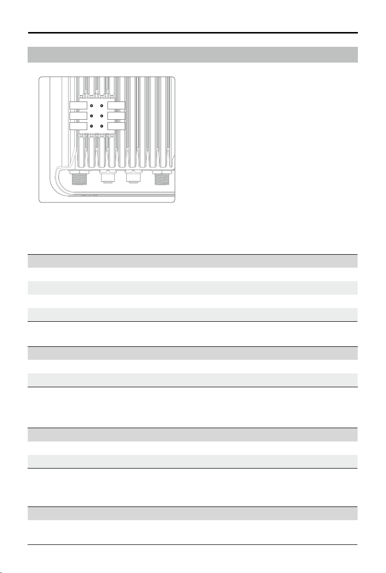
Indicators
LED1
LED2
LED3
LED4
LED5
LED6
LED1: Processor module status indicator
LED2: Network connection status indicator
LED3: UAV information capture indicator
LED4: Type 3 receiver status indicator
LED5: Type 2 receiver status indicator
LED6: Type 1 receiver status indicator
LED1: Processor module status indicator
It is used to indicate the processor’s working status.
Indicator Description
Green blinking Functioning normally or rmware updated successfully.
Yellow blinking Checking consistency when powered on or updating rmware.
Red blinking Firmware update failed.
Solid on/off Functioning abnormally.
Added two status when the rmware is updated to v03.00.00.23 or later.
Indicator Description
Yellow and red blinking alternatively Wireless dialing in progress.
Green and red blinking alternatively An abnormal SD card log was detected.
LED2: Network connection status indicator
It is used to indicate the connection status between the processor and server.
Indicator Description
Solid green Connected normally and communicating with the monitor.
Solid red Disconnected from the monitor.
Changed the solid green indicator and added ve status when the rmware is updated to
v03.00.00.23 or later.
Indicator Description
Solid green
2018 DJI All Rights Reserved.
©
4
Connected normally and communicating with the monitor via
Ethernet.
Page 7

Aeroscope AS-F1800
Green blinking
Yellow and red blinking
alternatively
Yellow blinking
Green and red blinking
alternatively
Connected normally and communicating with the monitor via a
Dongle.
Unable to get the server time.
The Server time got but SSL connection cannot be established
with the server.
SSL connection established but the sever heartbeat package
cannot be got.
Domain name resolution failed, including failure to connect
Red blinking
to the public network DNS server and unable to resolve the
domain name.
LED3: UAV information capture indicator
When the Aeroscope receives UAV information, it can indicate the number of UAVs in the
[4]
area.
Indicator Description
Green blinking
UAV detected, green LED blinking indicates UAV information
reception.
Off No UAV information received.
[4]
The UAV number is the reported number from the background. The same UAV serial number in a short
time is regarded as one.
LED4: Type 3 receiver status indicator
Indicator Description
Solid green Functioning normally.
Solid red Functioning abnormally.
LED5: Type 2 receiver status indicator
Indicator Description
Solid green Functioning normally.
Solid red Functioning abnormally.
LED6: Type 1 receiver status indicator
Indicator Description
Solid green Functioning normally.
Solid red Functioning abnormally.
2018 DJI All Rights Reserved.
©
5
Page 8

Function Descriptions
Basic Functions
Functions Descriptions
Aeroscope detects UAVs ying within a given area and obtains
each aircraft’s broadcast GPS coordinates, ight altitude,
UAV detection
Simple installation The processor and antennas can be easily installed onto the rod.
Support aircraft
GPS Aeroscope can detect its current position using its built-in GPS.
Remote OAM
Environmental spectrum
detection
Data security
speed, orientation, model, serial number, and Home Point.
Then Aeroscope sends this information to the remote server for
processing and to the display in real-time.
TM
PHANTOM
PHANTOMTM 4 series
INSPIRETM series
MAVICTM series
SPARK
MG-1P/T16/T20
MATRICETM series
A variety of OAM features are available when used with the
remote server, including rmware updating, resetting, status
inquiry, self-testing, parameter conguration, and more.
Aeroscope can scan for environmental interference and provide
a reference for installation.
Use certicate management and data encryption between the
equipment and remote server to ensure data reliability and
security.
3 series
TM
Features
Features Descriptions
In an interference-free environment, signal reception range
may be vary when different antennas are used. When using the
omnidirectional antenna (3dBi), signal reception range can reach:
Over 7 km for Mavic
Long-range detection
Easy installation Aeroscope can be installed and congured within half an hour.
2018 DJI All Rights Reserved.
©
6
Over 5 km for Phantom series
Over 3 km for Spark
The signal reception range is about twice as much as the
omnidirectional antenna when using the low-gain directional
antenna (8dBi) and about four times when using the high-gain
directional antenna (16dBi).
Page 9

Aeroscope AS-F1800
Support for multiple
antennas
Various data feedback
modes
Easy OAM capabilities
Error management
According to the environment and applications, users
can select appropriate antennas to meet their coverage
requirements.
Both Ethernet and 2G/3G/4G wireless networks are supported.
You can update rmware, reset to factory defaults, check
system status, conduct self-testing, adjust settings, and more
with the remote server and local app.
The device will reset when a recoverable software error
appears, and it will send a failure warning when there is an
unrecoverable software error or hardware error.
Operation and Maintenance
Modes Descriptions
Device management: All equipment status inquiries,
setting conguration, resetting, self-testing, and so on with
authorization.
Software management: Firmware updating and version
Online (Remote server)
Local (Assistant) Similar to online mode. But it can be used on one device.
management with authorization.
Environment monitoring: Monitor electromagnetic interference
to support equipment deployment and maintenance.
Data record management: Review data history within a
particular length of time with authorization.
2018 DJI All Rights Reserved.
©
7
Page 10

Installation
Lightning Protection
The Aeroscope stationary unit system includes surge protection modules in the antenna
module, power module, and Ethernet port. Aeroscope does not include a lightning induction
system, and should be installed within the protected region of another lightning induction
system. The protected region is calculated using the rolling sphere method.
The rolling sphere method assumes that an imaginary sphere of radius h
surface of a substation. The sphere rolls up and over (and is supported by) lightning masts,
shield wires, substation fences, and other grounded metallic objects that can provide
lightning shielding. A piece of equipment is said to be protected from a direct stroke if it
remains fully within the surface of the sphere.
For a simple scenario in which there is only one lightning rod standing on a at surface, the
maximum distance that the Aeroscope can be placed from the lightning rod and remain
within the protected region is calculated by the following equation:
Rx=√(h(2hr-h))-√(hx (2hr-hx))
Where:
rx is the maximum distance the Aerescope can be placed from the lightning rod.
hx is the height of the protected object.
h is the height of the lightning rod.
hr is the rolling sphere radius. It depends on the lightning density and the protected matter and
is given in the following table in the Chinese standard.
Protection Level Rolling Sphere Radius (m)
Type 1 30
Type 2 45
Type 3 60
exists above the
r
If Aeroscope is not under the protection of the nearest lightning rod, a designated lightning
induction system should be designed by a qualied professional.
Finally, be sure to note the following:
Ensure that rainwater cannot ow along the Antenna cable into the Aeroscope receiver.
If the pole is made of metal, the frame and the pole should be separated using insulation.
Indoor power outlets must have surge protection.
Indoor Ethernet outlets must have surge protection.
Step-by-Step Installation Guide
For permanent setups, the Aeroscope unit can be mounted anywhere that meets all installation
requirements, such as Lightning Protection, height restrictions, power connection, and network
connection. The most common installation scenario is to attach it to a pole on the rooftop.
The standard procedure for pole-mounted scenarios is as follows:
1. The pole should be rmly xed to the ground (or other solid surface such as a rooftop).
The diameter of the pole plus the insulation layer should be 120 mm to utilize the frames
supplied with the stationary unit and antennas.
2018 DJI All Rights Reserved.
©
8
Page 11

Aeroscope AS-F1800
2. Attach the stationary unit and the antennas to the pole. The processes for installing the
stationary unit, G8 antennas, and G16 antennas are illustrated in below gures respectively.
Attaching the stationary unit to the pole
Attaching the G8 antennas to the pole
Attaching the G16 antennas to the pole
3. Connect the antennas to the unit via the antenna cable.
a. If using G8 directional antennas, connect each antenna to one antenna port of the stationary
unit with an antenna cable. Note that two adjacent antennas should be connected to ports
at the top of the stationary unit, while the other two adjacent antennas should be connected
to ports at the bottom. This ensures diversity gains will be realized. Below gure shows the
connection conguration between the G8 antennas and the stationary unit.
2018 DJI All Rights Reserved.
©
9
Page 12

Aeroscope AS-F1800
Connection conguration between
G8 antennas and the stationary unit
b. If using G16 high-gain antennas, the 2.4GHz antenna should be connected to a 5.8GHz
antenna. Each 5.8GHz antenna has two antenna cable ports. The port marked “OUT” is
for connecting to the Aeroscope unit, and the port marked “IN” is for connecting to the
2.4GHz antenna. Below gure shows the connection conguration and close-up view of
a 2.4GHz antenna.
(a) (b)
(a) The connections between the 2.4GHz antennas and the 5.8GHz antennas in G16
antennas installations. (b) The “IN” and “OUT” ports on a 5.8GHz G16 antenna.
4. Often, the supplied power cable is too short for the connection between the stationary unit
and the nearest available power outlet. In such cases, a qualied electrical engineer must
extend the initial power cable to complete the connection.
5. After powering on, check the LED indicators with reference to the Indicators section.
6. Download DJI Assistant 2.
from https://www.dji.com/aeroscope/info#downloads
7. Install and run DJI Assistant 2 on a windowns computer (desktop or laptop).
8. Connect the computer and the Aeroscope unit to the same router, or connect them directly
via the Ethernet port.
9. After the Aeroscope stationary unit is found on the DJI Assistant 2 start page, set the
server IP and Port in Network Settings>Server Network Settings.
10. Set the network mode to Wireless if using a wireless dongle. Set to Wired if using an
Ethernet connection. Depending on network provider requirements, set the parameters
manually or set the mode to Auto.
2018 DJI All Rights Reserved.
©
10
Page 13

Aeroscope AS-F1800
11. Exit DJI Assistant 2.
12. Restart the stationary unit.
13. Connect the stationary unit to the internet.
a. It is recommended to always use Ethernet when possible, because the connection is
stable and free of interference.
b. If using a wireless connection, the dongle must be installed with an active SIM card.
You may need to congure some parameters such as APN in DJI Assistant 2.
14. Log into the Aeroscope web server https://Aeroscope.djiservice.org using your assigned
account. The account management system in Aeroscope manages the relations between
each account and each Aeroscope unit. Make sure the DJI admin has added your unit to
your account. Otherwise, you will not see your unit when you log in.
Importing Certicates
In most cases, when you receive your Aeroscope stationary unit the certicate should already
be imported. If the certificate doesn’t work or has expired, you will need to import a new
certicate manually.
To import a new certicate, follow this procedure:
1. Acquire the certicate les from DJI. A single certicate consists of two les.
2. Download DJI Assistant 2.
3. Install and run DJI Assistant 2 on a windows computer (desktop or laptop).
4. Connect the computer and the Aeroscope unit to the same router or connect them directly
via the Ethernet port.
5. After the stationary unit is found in Aeroscope, click it to enter the unit page. Under
Advanced Functions, select the certicate. Import the certicate by selecting both les.
Power Cable Usage
Introduction
The Aeroscope Power Cable is used to connect the Aeroscope stationary unit to a power
supply. You can connect it directly if it is long enough for your needs. Otherwise, you can
extend it using the procedures provided below. In addition, the power cable can also be
converted into a DC power cable if necessary.
In the Box
Power Cable × 1 Plug Pin × 5 Female plug bracket × 1
Various according to
different national standards
2018 DJI All Rights Reserved.
©
11
Page 14

Aeroscope AS-F1800
Live wire
Ground wire
Neutral wire
Modifying the Power Cable
You can use either of the rst two procedures below to extend the power cable if it is not long
enough for your needs. Additionally, you can use the third procedure to convert it into a DC
power cable if necessary.
Procedure 1: Extending the AC Power Cable (New Plug Bracket)
1. Loosen the nut that seals the cable in the waterproof module, and remove the screw on
the top of the module to open it.
2. Cut off the original female plug bracket. Remove the power cable and replace it with a
longer one provided by yourself.
3. Solder the provided plug pins onto the neutral and live wires of the new power cable
(crimping pliers can also be used), then plug the two pins into the female plug bracket
provided in the box.
4. Remove the screw on the ground wire connector of the female plug bracket, then insert
the ground wire of the power cable into the female plug bracket and retighten the screw.
5. Insert the female plug bracket into the waterproof module and tighten the screw. Tighten
the nut to ensure a good seal between the cable and waterproof module.
2018 DJI All Rights Reserved.
©
12
Live wire
Ground wire
Neutral wire
Ground wire
Live wire
Neutral wire
Page 15

Aeroscope AS-F1800
Procedure 2: Extending the AC Power Cable (Original Plug Bracket)
1. Loosen the nut that seals the cable in the waterproof module, and remove the screw on
the top of the module to open it.
2. Cut off the original female plug bracket. Remove the power cable and replace it with a
longer one provided by yourself.
3. Solder the original female plug bracket onto the new power cable.
4. Insert the female plug bracket into the waterproof module and tighten the screw. Tighten
the nut to ensure a good seal between the cable and waterproof module.
Procedure 3: Converting to a DC Power Cable
Follow the procedure shown in the gure below to convert the power cable to a DC power cable.
The modication procedure is the same as that of Procedure 1 for extending an AC power cable, but different
pins are required. Connect the cable wires to the DC negative and DC positive poles on the female plug
bracket to use the cable as a DC power cable.
DC negative pole
DC positive pole
2018 DJI All Rights Reserved.
©
13
Page 16

Aeroscope AS-F1800
After Modication
1. Make sure the screw and washer on the waterproof module are securely tightened to x
the female plug bracket in place.
2. After securing the female plug bracket in place, make sure to tighten the nut. The internal
rubber on the nut should form a tight seal to ensure that the cable and plug are waterproof.
1
2
2018 DJI All Rights Reserved.
©
14
Page 17

Specications
Safety and Standards
Model AS-F1800
Ingress Protection Rating IP65
Lightning Rating IEC61000-4-5 6KV
This equipment meets electromagnetic compatibility
requirements and also meets below criteria:
Europe:
Electromagnetic
Compatibility
Electrical Specications
Power Consumption
Input 100-240 V~, 50/60 Hz, 2.5 A Max.
Working Environment
Operating Temperature
Relative Humidity 5% to 100%
Absolute Humidity 1 g/m
Atmospheric Pressure 70 kPa to 106 kPa
Physical Specications
Dimensions (HxWxD) 310 mm × 260 mm × 100 mm
Weight 6.8 kg
Support Aircraft
[5]
Test temperature is the room temperature of 25 ° C.
EN 55032: 2015
EN 55024: 2010+A1:2015
EN 61000-3-2: 2014
EN 61000-3-3: 2013
United States:
47 CFR Part 15, Subpart B:2016
[5]
Approx. 70W
-30°C to +50°C (without solar radiation)
-30°C to +45°C (with solar radiation)
3
to 30 g/m
3
Phantom 3 series
Phantom 4 series
Inspire series
Mavic series
Spark
MG-1P/T16/T20
Matrice series
2018 DJI All Rights Reserved.
©
15
Page 18

Compliance Notice
NOTE: This equipment has been tested and found to comply with the limits for a Class A digital device, pursuant to part 15 of
the FCC Rules. These limits are designed to provide reasonable protection against harmful interference when the equipment
is operated in a commercial environment. This equipment generates, uses, and can radiate radio frequency energy and, if
not installed and used in accordance with the instruction manual, may cause harmful interference to radio communications.
Operation of this equipment in a residential area is likely to cause harmful interference in which case the user will be required
to correct the interference at his own expense.
EU Compliance Statement: SZ DJI TECHNOLOGY CO., LTD. hereby declares that this device is in compliance with the
essential requirements and other relevant provisions of the Directive 2014/53/EU.
A copy of the EU Declaration of Conformity is available online at www.dji.com/euro-compliance
EU contact address: DJI GmbH, Industriestrasse 12, 97618, Niederlauer, Germany
Declaración de cumplimiento UE: SZ DJI TECHNOLOGY CO., LTD. por la presente declara que este dispositivo cumple los
requisitos básicos y el resto de provisiones relevantes de la Directiva 2014/53/EU.
Hay disponible online una copia de la Declaración de conformidad UE en www.dji.com/euro-compliance
Dirección de contacto de la UE: DJI GmbH, Industriestrasse 12, 97618, Niederlauer, Germany
EU-verklaring van overeenstemming: SZ DJI TECHNOLOGY CO., LTD. verklaart hierbij dat dit apparaat voldoet aan de
essentiële vereisten en andere relevante bepalingen van Richtlijn 2014/53/EU.
De EU-verklaring van overeenstemming is online beschikbaar op www.dji.com/euro-compliance
Contactadres EU: DJI GmbH, Industriestrasse 12, 97618, Niederlauer, Germany
Declaração de conformidade da UE: A SZ DJI TECHNOLOGY CO., LTD. declara, através deste documento, que este
dispositivo está em conformidade com os requisitos essenciais e outras disposições relevantes da Diretiva 2014/53/EU.
Existe uma cópia da Declaração de conformidade da UE disponível online em www.dji.com/euro-compliance
Endereço de contacto na UE: DJI GmbH, Industriestrasse 12, 97618, Niederlauer, Germany
Dichiarazione di conformità UE: SZ DJI TECHNOLOGY CO., LTD. dichiara che il presente dispositivo è conforme ai requisiti
essenziali e alle altre disposizioni rilevanti della direttiva 2014/53/EU.
Una copia della dichiarazione di conformità UE è disponibile online all'indirizzo Web www.dji.com/euro-compliance
Indirizzo di contatto UE: DJI GmbH, Industriestrasse 12, 97618, Niederlauer, Germany
Déclaration de conformité UE: Par la présente, SZ DJI TECHNOLOGY CO., LTD déclare que cet appareil est conforme aux
principales exigences et autres clauses pertinentes de la directive européenne 2014/53/EU.
Une copie de la déclaration de conformité UE est disponible sur le site www.dji.com/euro-compliance
Adresse de contact pour l'UE : DJI GmbH, Industriestrasse 12, 97618, Niederlauer, Germany
EU-Compliance: Hiermit erklärt SZ DJI TECHNOLOGY CO., LTD., dass dieses Gerät den wesentlichen Anforderungen und
anderen einschlägigen Bestimmungen der EU-Richtlinie 2014/53/EU entspricht.
Eine Kopie der EU-Konformitätserklärung nden Sie online auf www.dji.com/euro-compliance.
Kontaktadresse innerhalb der EU: DJI GmbH, Industriestrasse 12, 97618, Niederlauer, Germany
CAUTION: RISK OF EXPLOSION IF BATTERY IS REPLACED BY AN INCORRECT TYPE. DISPOSE OF USED BATTERIES
ACCORDING TO THE INSTRUCTIONS
Equipment intended only for installation in a RESTRICTED ACCESS LOCATION.
For PLUGGABLE EQUIPMENT, the socket-outlet shall be installed near the equipment and shall be easily accessible.
「アクセスに制限がある場所での取り付けを想定しています。
プラグ着脱可能な機器の場合、コンセントの近くに機器を設置し、アクセスしやすいようにしてください。」
2018 DJI All Rights Reserved.
©
16
Page 19

This content is subject to change.
Download the latest version from
https://www.dji.com/aeroscope
If you have any questions about this document, please
contact DJI by sending a message to
DocSupport@dji.com
Copyright © 2018 DJI All Rights Reserved.
YC.BZ.SS000200.07
.
Printed in China.
 Loading...