

Page 1
AGRAS T20
User Manual
2020.11
v1.2
Page 2
Searching for Keywords
Search for keywords such as “battery” and “install” to nd a topic. If you are using Adobe Acrobat
Reader to read this document, press Ctrl+F on Windows or Command+F on Mac to begin a search.
Navigating to a Topic
View a complete list of topics in the table of contents. Click on a topic to navigate to that section.
Printing this Document
This document supports high resolution printing.
Page 3
Information
1. The AGRASTM T20 does not come with a ight battery. Only purchase ofcial DJITM ight batteries
(model: AB3-18000mAh-51.8V). Read the T20 Intelligent Flight Battery User Guide and take
necessary precautions when handling the batteries to ensure your own safety. DJI assumes no
liability for damage or injury incurred directly or indirectly from misusing batteries.
2. In this document, the altitude limit of 30 m means the altitude between the aircraft and the surface
of the objects below it when the altitude stabilization function of the radar module is enabled. If the
function is disabled, the altitude limit means the altitude between the aircraft and the takeoff point.
Using This Manual
Legend
Important Hints and tips Reference
Before Flight
The following documents have been produced to help you safely operate and make full use of your
aircraft:
1. In the Box
2. Disclaimer and Safety Guidelines
3. Quick Start Guide
4. User Manual
Refer to the Agras T20 In the Box to check the listed parts and read the disclaimer and safety guidelines
before ight. Refer to the quick start guide for more information on assembly and basic operation. Refer
to the user manual for more comprehensive information.
Downloading DJI Assistant 2 for MG
Download DJI ASSISTANTTM 2 for MG from:
https://www.dji.com/t20/downloads
The operating temperature of this product is 0° to 40° C (32° to 104° F). It does not meet
the standard operating temperature for military grade application (-55° to 125° C (-67° to
257° F)), which is required to endure greater environmental variability. Operate the product
appropriately and only for applications that it meets the operating temperature range
requirements of that grade.
2020 DJI All Rights Reserved.
©
1
Page 4

Safety at a Glance
1. Pesticide Usage
•
Avoid the use of powder pesticides as much as
possible as they may reduce the service life of the
spraying system.
•
Pesticides are poisonous and pose serious risks to
safety. Only use them in strict accordance with their
specications.
•
Residue on the equipment caused by splashes or
spills when pouring and mixing the pesticide can
Note that the Safety at a Glance section
only provides a quick overview of the
safety tips. Make sure you read and
understand this document and the
Agras T20 User Manual.
irritate your skin. Make sure to clean the equipment
after mixing.
•
Use clean water to mix the pesticide and lter the mixed liquid before pouring into the spray
tank to avoid blocking the strainer. Clear any blockage before using the equipment.
•
Make sure to stay in an upwind area when spraying pesticide to avoid bodily harm.
•
Wear protective clothing to prevent direct body contact with the pesticide. Rinse your hands
and skin after handling pesticides. Clean the aircraft and remote controller after applying the
pesticide.
•
Effective use of pesticides depends on pesticide density, spray rate, spray distance, aircraft
speed, wind speed, wind direction, temperature, and humidity. Consider all factors when
using pesticides, but DO NOT compromise the safety of people, animals, or the environment in
doing so.
•
DO NOT contaminate rivers and sources of drinking water.
2. Environmental Considerations
•
Fly at locations that are clear of buildings and other obstacles. DO NOT y above or near large
crowds.
•
The recommended maximum operating altitude is 2 km (6,560 ft) above sea level. DO NOT y
over 3 km (9,842 ft) above sea level.
•
Only y in moderate weather conditions with temperatures between 0° and 40° C (32° and
104° F).
•
Make sure that your operations do not violate any applicable laws or regulations, and that you
have obtained all appropriate prior authorizations. Consult the relevant government agency
or authority, or your lawyer before flight to ensure you comply with all relevant laws and
regulations.
•
DO NOT operate any part of the aircraft indoors.
The Agras T20 aircraft is
not a toy and is not suitable
for children under the age
of 18.
3. Pre-Flight Checklist
Make sure to check all of the following:
•
Remote controller and aircraft batteries are fully charged.
•
All parts are in good condition. Replace aged or broken parts before ight.
•
Landing gear and spray tank are rmly in place.
•
Propellers and frame arms are unfolded and arm sleeves are rmly tightened. Propellers are in
good condition and rmly tightened. There is nothing obstructing the motors and propellers.
•
Spraying system is not blocked and works properly.
•
Compass is calibrated after being prompted to do so in the app.
4. Ingress Protection Rating Description
The T20 is waterproof, dustproof, and corrosion-resistant when it is functioning normally. Under
stable laboratory conditions, the aircraft has a protection rating of IPX6 (IEC standard 60529)
2020 DJI All Rights Reserved.
©
2
Page 5

AGRAS T20
User Manual
and can be cleaned using a small amount of water. The aerialelectronics system (barometer
excluded), spray control system, ESC system, and radar module has a protection rating of up to
IP67. However, this protection rating is not permanent and may reduce over time after long-term
use due to aging and wear. The product warranty does not cover water damage. The protection
ratings of the aircraft mentioned above may decrease in the following scenarios:
• There is a collision and the seal structure is deformed.
• The seal structure of the shell is cracked or damaged.
• The waterproof covers are not properly secured.
5. Operation
•
Stay away from the rotating propellers and motors.
•
The takeoff weight must not exceed 45.5 kg when using near sea level. Note that when using
at a higher sea level, the takeoff weight capacity will be reduced.
•
Once the operating altitude reaches 1 km (3,280 ft), the payload capacity of the spray tank is
reduced by 2 kg. For every additional km, the payload capacity will be reduced another 2 kg.
•
Maintain a visual line of sight (VLOS) of your aircraft at all times.
•
DO NOT use the Combination Stick Command (CSC) or other methods to stop the motors
when the aircraft is airborne unless in an emergency situation.
•
DO NOT answer incoming calls during ight. DO NOT y under the inuence of alcohol or drugs.
•
If there is a low battery warning, land the aircraft at a safe location.
•
If the radar module is unable to work properly in the operating environment, the aircraft will be
unable to avoid obstacles during Return to Home (RTH). All that can be adjusted is the ight
speed and altitude, as long as the remote controller is still connected.
•
After landing, stop the motors, power off the aircraft, and power off the remote controller.
Otherwise, the aircraft may enter Failsafe RTH automatically due to remote controller signal loss.
•
Maintain full control of the aircraft at all times and do not rely on the DJI Agras app. The
obstacle avoidance function is disabled in certain situations. Keep the aircraft within VLOS and
pay close attention to its ight. Use your discretion to operate the aircraft and manually avoid
obstacles in a timely manner. It is important to set an appropriate Failsafe and RTH altitude
before each ight.
6. Maintenance and Upkeep
•
DO NOT use aged, chipped, or broken propellers.
•
To avoid damaging the landing gear, remove or empty the spray tank during transportation or
when not in use.
•
Recommended storage temperature (when the spray tank, ow meter, pumps, and hoses are
empty): -20° to 40° C (-4° to 104° F).
•
Clean the aircraft immediately after spraying. Inspect the aircraft regularly. Refer to Product
Care in the Agras T20 Disclaimer and Safety Guidelines for more information about
maintenance guidelines.
7. Observe Local Laws and Regulations
•
You can find a list of DJI GEO zones at http://www.dji.com/flysafe. Note that the DJI GEO
zones are not a replacement for local government regulations or good judgment.
•
Avoid ying at altitudes above 30 m (98 ft).*
* In this document, the altitude limit of 30 m means the altitude between the aircraft and the surface of the objects below it
when the altitude stabilization function of the radar module is enabled. If the function is disabled, the altitude limit means
the altitude between the aircraft and the takeoff point.
The ying altitude limit varies in different countries or regions. Make sure to y at the altitudes outlined by local laws and regulations.
2020 DJI All Rights Reserved.
©
3
Page 6
AGRAS T20
User Manual
30 m
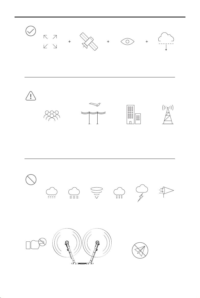
Fly in Open Areas VLOSStrong GNSS Signal Fly Below 30
Avoid ying over or near crowds, high voltage power lines, or bodies of water.
Strong electromagnetic sources such as power lines, base stations, and tall buildings may
affect the onboard compass.
m (98 ft)
≥8 m/s
2020 DJI All Rights Reserved.
©
4
DO NOT use the aircraft in adverse weather conditions such as winds exceeding 28 kph (17
mph), heavy rain (precipitation rate exceeding 25 mm (0.98 in) in 12 hours), fog, snow, lightning,
tornadoes, or hurricanes.
GEO Zones
Stay away from the rotating
propellers and motors.
Learn more at:
http://www.dji.com/ysafe
Page 7

Contents
Information
Using This Manual
Legend 1
Before Flight 1
Downloading DJI Assistant 2 for MG 1
Safety at a Glance
Contents
Product Prole
Introduction 7
Feature Highlights 7
Preparing the Aircraft 8
Preparing the Remote Controller 9
Aircraft Overview 11
Remote Controller Overview 12
Aircraft
Aircraft Prole 14
Flight Modes 14
Operation Modes 14
Operation Resumption 21
System Data Protection 23
Omnidirectional Digital Radar 23
Empty Tank 26
Return to Home (RTH) 26
Low Battery and Low Voltage Warnings 28
RTK Functions 28
Aircraft LEDs 29
1
1
2
5
7
14
Remote Controller
Prole 30
Using the Remote Controller 30
2020 DJI All Rights Reserved.
©
30
5
Page 8

AGRAS T20
User Manual
Remote Controller LEDs 37
Remote Controller Warning Sounds 38
Linking the Remote Controller 38
DJI Agras App
Home Screen 39
Operation View 40
Flight
Operation Environment 44
Flight Limits and GEO Zones 44
Pre-Flight Checklist 46
Calibrating the Spraying System 46
Discharging the Bubbles in the Hoses 47
Calibrating the Compass 47
Starting and Stopping the Motors 49
Flight Test 50
DJI Assistant 2 for MG
Installation and Launching 51
Using DJI Assistant 2 for MG 51
Appendix
Specications 52
Aircraft Status Indicators Description 56
Updating the Firmware 56
39
44
51
52
2020 DJI All Rights Reserved.
©
6
Page 9

Product Prole
Introduction
The Agras T20 features a brand-new design including a foldable frame and a quick-release
spray tank and ight battery, making replacement, installation, and storage easy. The stable and
reliable modular aerial-electronics system is integrated with a dedicated industrial ight controller,
OCUSYNCTM 2.0 HD transmission system, and RTK module. It has dual IMUs and barometers and
adopts a propulsion control system redundancy design including both digital and analog signals to
ensure ight safety.
The GNSS+RTK dual-redundancy system is compatible with GPS, GLONASS, BeiDou, and Galileo.
The T20 also supports centimeter-level positioning
antenna technology provides strong resistance against magnetic interference.
The upgraded spraying system features an improvement in payload. It also has a 4-channel
electromagnetic ow meter to ensure consistent spraying for all sprinklers.
The new-generation omnidirectional digital radar provides functions such as terrain following and
obstacle sensing and circumventing in all horizontal directions. The aircraft is equipped with a wideangle FPV camera that enables users to observe the landscape from the front of the aircraft.
The aircraft has a backup power system, which supplies power to the aircraft for approximately
20 seconds when the Intelligent Flight Battery is powered off due to malfunction during ight. This
allows the aircraft to avoid accident and land safely.
Due to its industrial design and material, the T20 is dustproof, waterproof, and corrosion-resistant. The
aircraft has a protection rating of IPX6 (IEC standard 60529), while the protection rating of the aerialelectronics system, spray control system, propulsion ESC system, and radar module is up to IP67.
The Smart Controller 2.0 uses the DJI OcuSync 2.0 transmission system, has a maximum control
distance of up to 3 km
[2]
, and supports Wi-Fi and Bluetooth functions. The remote controller is
equipped with a 5.5-inch bright, dedicated screen that has the DJI Agras app built in, signicantly
improving smoothness and stability. When the RTK dongle is connected to the remote controller,
users can plan operations to centimeter-level precision. The Multi-Aircraft Control mode of the
remote controller can be used to coordinate the operation of up to ve aircraft at the same time,
enabling pilots to work efficiently. Both the built-in battery and external battery can be used to
supply power to the remote controller. The total working time is up to 4 hours, which fully meets the
requirements for long and high-intensity operations.
[1]
when used with the onboard D-RTKTM. Dual-
Feature Highlights
The modular design of the T20 simplies assembly. The airframe can be quickly folded, making
it easy for transportation. Both the Intelligent Flight Battery and spray tank are easily swappable,
signicantly improving the efciency of power and liquid supply.
The T20 has an aerial-electronics system with a multiple redundancy design, and also has onboard
D-RTK antennas, supporting dual-antenna technology that provides strong resistance against
magnetic interference to ensure ight safety.
Thanks to the dedicated DJI industrial ight control system, the T20 offers four operation modes:
[1] The remote controller is able to reach its maximum transmission distance (FCC / NCC: 5 km (3.11 mi); CE / KCC / MIC / SRRC:
3 km (1.86 mi)) in an open area with no electromagnetic interference, and at an altitude of approximately 2.5 m (8.2 ft).
[2] The remote controller is able to reach its maximum transmission distance (FCC / NCC: 5 km (3.11 mi); CE / KCC / MIC / SRRC:
3 km (1.86 mi)) in an open area with no electromagnetic interference, and at an altitude of approximately 2.5 m (8.2 ft).
2020 DJI All Rights Reserved.
©
7
Page 10
AGRAS T20
User Manual
Route, A-B Route, Manual, and Manual Plus.
DJI Agras app automatically produces flight routes based on your planned fields. To start,
simply select the eld from the eld list. Plan a eld by walking with the remote controller, an RTK
Dongle, an RTK handheld mapping device, or by ying the aircraft to waypoints, according to the
application scenarios. In scenarios with complicated terrain, use the Phantom 4 RTK and DJI Terra
to plan 3D ight routes, and import the routes to DJI Agras for operation.
In A-B Route operation mode, the aircraft travels along a planned route and sprays its liquid
payload. Users can set the line spacing, ying speed, and other parameters.
In Manual operation mode, users can start and stop spraying manually and also adjust the spray rate.
In Manual Plus operation mode, the ight speed is restricted and the heading is locked. Except for
the heading, users can control the movement of the aircraft via the control sticks. Press button C1
or C2 on the remote controller or the corresponding button in the app and the aircraft will y one
line spacing to the left or right. Note that button C1 and button C2 are customizable in the app.
The T20 also includes the Operation Resumption function. When pausing the operation in Route or
A-B Route operation mode, Operation Resumption records a breakpoint for the aircraft. Users can
resume from the breakpoint when continuing the operation.
The omnidirectional digital radar works automatically in Route, A-B Route, and Manual Plus
operation modes during both day and night, without being affected by light or dust. Altitude
detection and stabilization functions are available in forward, backward, and downward directions
while Obstacle Avoidance is available in all horizontal directions. The radar module can detect
the angle of a slope and automatically adjust to maintain the same distance with the surface even
in mountainous terrain. In Route and A-B Route operation modes, the radar can effectively sense
obstacles and plan a ight route to actively circumvent obstacles in all horizontal directions. Note
that this is disabled by default. Users can enable it in the app.
The remote controller features Multi-Aircraft Control mode (coming soon), which can be used to
coordinate the operation of up to ve aircraft simultaneously. Turn the aircraft control switch dial on
the remote controller to switch control between different aircraft.
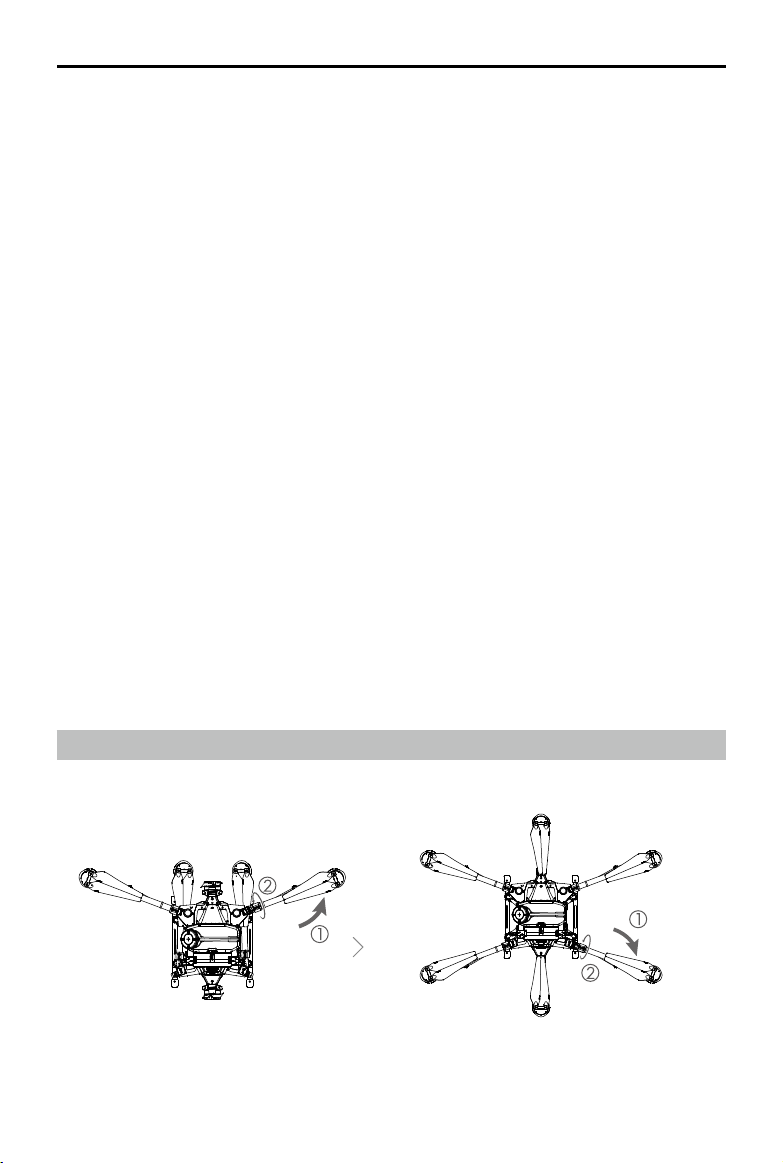
Preparing the Aircraft
M2
Unfold the M2 and M6 arms, and
tighten the two arm sleeves.
2020 DJI All Rights Reserved.
©
8
M6
M1
M3
M4
M5
Unfold the M3 and M5 arms followed by M1 and
M4, and then tighten the four arm sleeves.
Page 11
AGRAS T20
User Manual
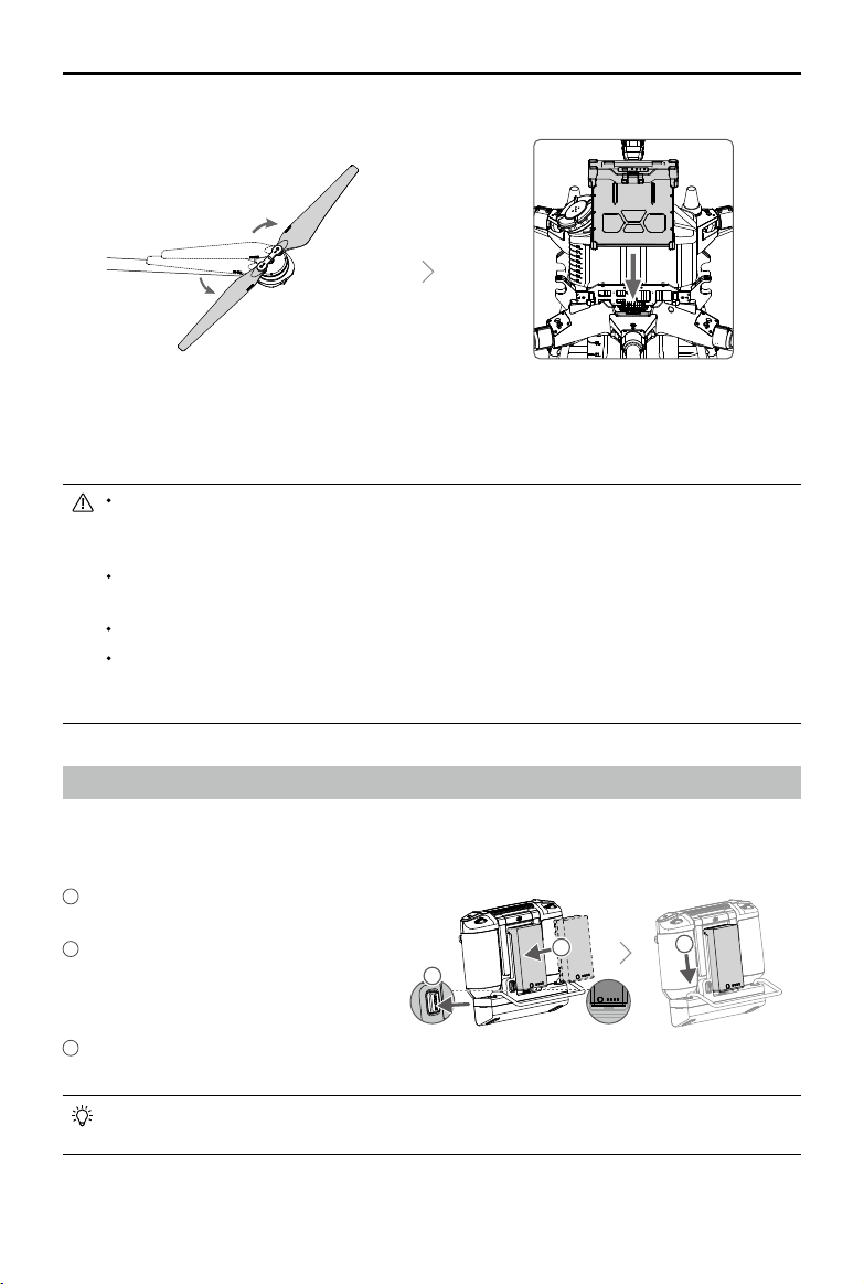
Unfold the propeller blades. Insert the Intelligent Flight Battery into the
aircraft until you hear a click.
Before using the aircraft, make sure to mount the backup battery. Otherwise, the aircraft cannot
take off. Mount and use the backup battery in strict accordance with the Agras T20 Backup
Battery User Guide.
Make sure that the battery is rmly inserted into the aircraft. Only insert or remove the battery
when the aircraft is powered off.
To remove the battery, press and hold the clamp, and then lift the battery up.
When folding the arms, make sure to fold the M3 and M5 arms rst, and then the M2 and M6
arms. Otherwise, the arms may be damaged. Lift and lower the M1 and M4 arms gently to
reduce wear and tear.
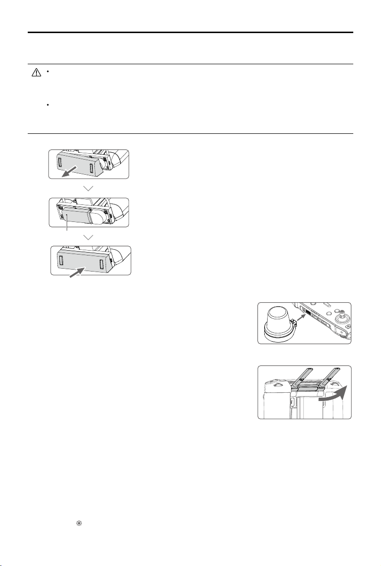
Preparing the Remote Controller
Mounting the External Battery
1
Press and hold the battery release
button.
2
Insert the Intelligent Battery into the
battery compartment. Make sure the
1
bottom of the battery is aligned to the
marking line in the compartment.
3
Push the battery to the bottom.
To remove the Intelligent Battery, press and hold the battery release button, then push the
battery upward.
2
2020 DJI All Rights Reserved.
©
3
9
Page 12
AGRAS T20
User Manual
Mounting the 4G Dongle and SIM Card
Only use a DJI-approved dongle. The dongle supports various network standards. Use a SIM
card that is compatible with the chosen mobile network provider, and select a mobile data plan
according to the planned level of usage.
The dongle and SIM card enable the remote controller to access specific networks and
platforms, such as the DJI AG platform. Make sure to employ them correctly. Otherwise,
network access will not be available.
Remove the dongle compartment cover.
Insert the dongle into the USB port with the SIM card inserted
into the dongle, and test the dongle.*
Dongle
Reattach the cover rmly.
Mounting the RTK Dongle
When using the RTK planning method to plan the operation area,
attach the RTK dongle to the USB-A port on the remote controller.
Adjusting the Antennas
Lift the antennas and adjust them. The strength of the remote
controller signal is affected by the position of the antennas. When
the angle between the antennas and the back of the remote
controller is 80° or 180°, the connection between the remote
controller and aircraft can reach its optimal performance.
* Test procedure: Press the remote controller power button once, then press again and hold to power the remote controller on.
In DJI Agras, tap
devices in the network chain are shown in green.
2020 DJI All Rights Reserved.
©
10
, and select Network Diagnostics. The dongle and SIM card are functioning properly if the status of all the
Page 13
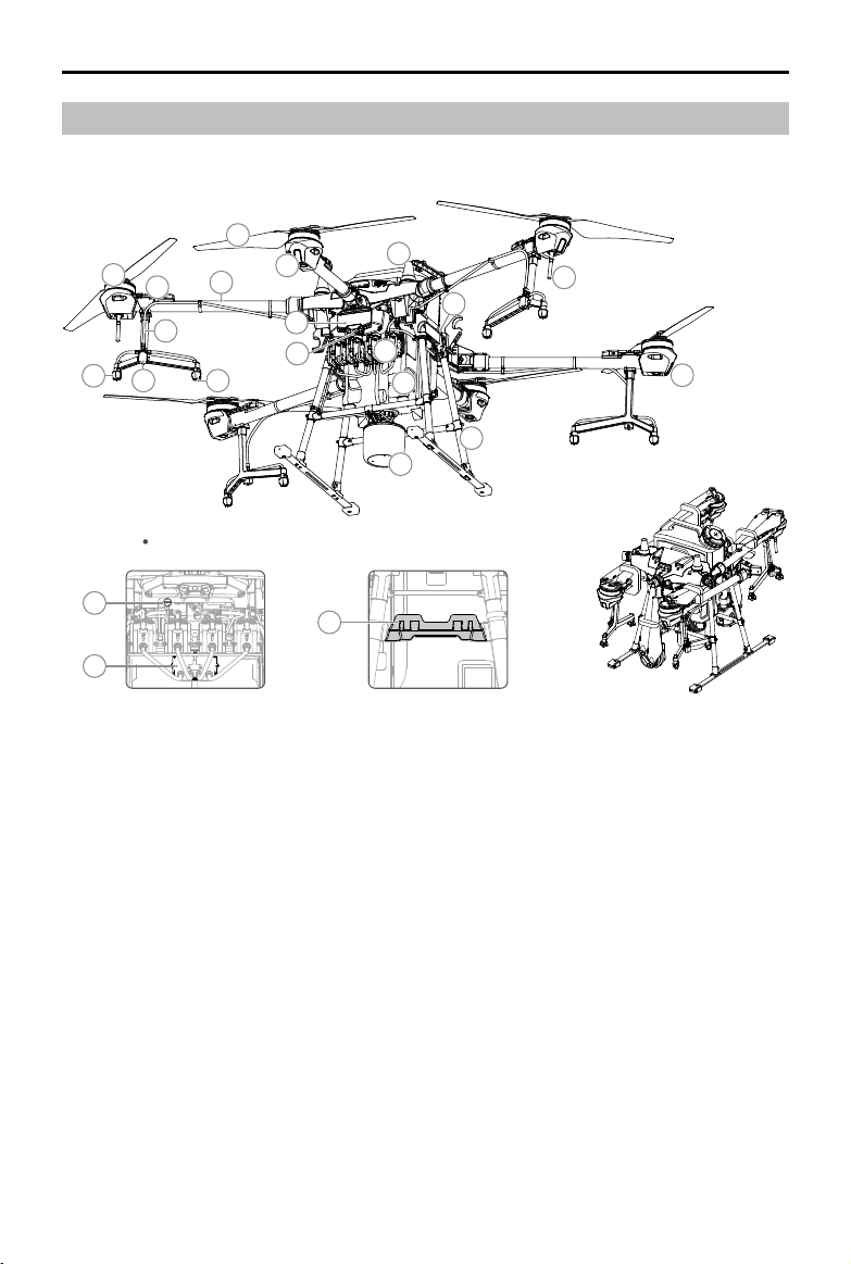
Aircraft Overview
AGRAS T20
User Manual
1
2
7
8
Aircraft Front
12
13
4
3
6
9
5
10
11
22
1. Propellers
2. Motors
3. ESCs
4. Frame Arms
5. Aircraft Front Indicators (on the three
front arms)
6. Hoses
7. Sprinklers
8. Electromagnetic Exhaust Valves
9. Nozzles
10. Aerial-Electronics System
11. FPV Camera
12. USB-C Port (on the bottom of the
aerial-electronics system, under the
waterproof cover)
20
19
18
14
17
16
15
FoldedRight ViewBottom View
13. 4-Channel Electromagnetic Flow Meter
14. Delivery Pumps
15. Omnidirectional Digital Radar
16. Landing Gear
17. Spray Tank
18. Battery Compartment
19. OcuSync Antennas
20. Onboard D-RTK Antennas
21. Aircraft Status Indicators (on the three
rear arms)
22. Remote Controller Holder
21
2020 DJI All Rights Reserved.
©
11
Page 14
AGRAS T20
22
24
25
26
27
23
15
16
17 18 19
20
21
User Manual
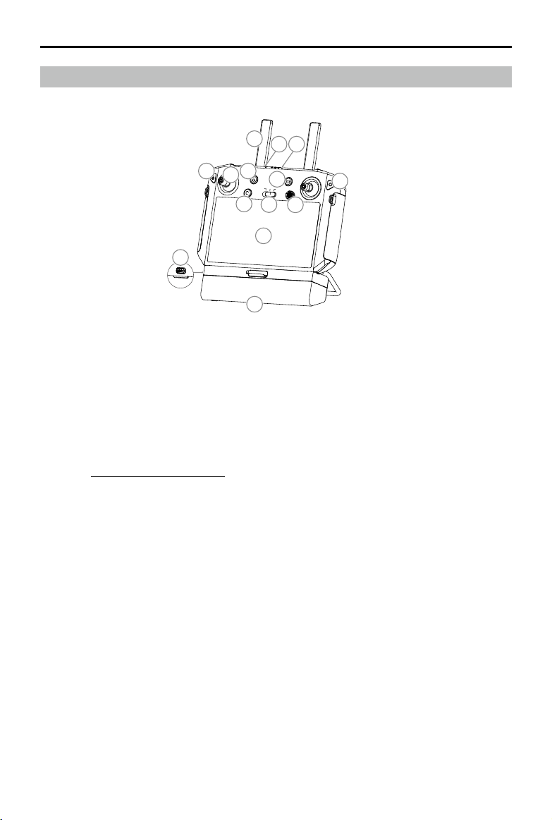
Remote Controller Overview
13
1
7
8
2
4
3
10
5
6
9
11
12
14
1. Antennas
Relays aircraft control and image transmission
signal.
2. Back Button / Function Button
Press once to return to the previous page and
press twice to go back to the homepage. Hold
to view a guide to using button combinations.
Refer to Button Combinations (p. 36) for more
information.
3. Control Sticks
Controls aircraft movement. Control mode can
be set in the app.
4. RTH Button
Press and hold this button to initiate RTH.
5. Button C3 (customizable)
6. Flight Mode Switch
The three positions are P-mode (Positioning),
A-mode (Attitude), and P-mode (Positioning).
7. Status LED
Indicates whether the remote controller is
linked to the aircraft.
2020 DJI All Rights Reserved.
©
12
8. Battery Level LEDs
Displays current battery level of the internal
battery.
9. 5D Button (customizable)
10. Power Button
Used to power the remote controller on and
off. When the remote controller is powered
on, press the button to enter sleep mode or to
wake up the controller.
11. Conrm Button
Press to conrm a selection.
12. Touch Screen
Tap to select. Android-based device to run
DJI Agras.
13. USB-C Charging Port
Use to charge the remote controller.
14. Dongle Compartment Cover
Open the cover to mount or remove the 4G
dongle.
Page 15
AGRAS T20
22
24
25
26
27
23
22
24
23
User Manual
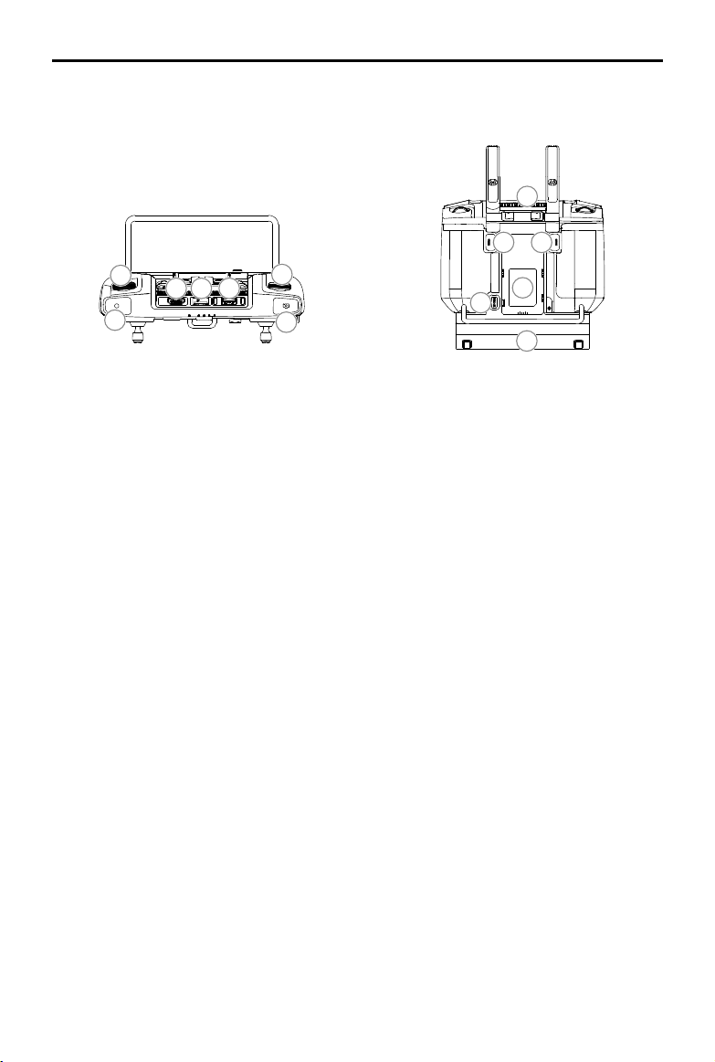
15
17 18 19
16
15. Spray Rate Dial
Turn to adjust the spray rate in Manual
operation mode.
16. Spray Button
Press to start or stop spraying in Manual
operation mode.
17. HDMI Port
For video output.
18. microSD Card Slot
Used to insert a microSD card.
19. USB-A Port
Used to connect devices such as an RTK
Dongle, or to connect to a computer to
update firmware and obtain data stored in
the remote controller via the DJI Assistant 2
software.
20. FPV / Map Switch Button
In Operation View in DJI Agras, press to
switch between FPV and the Map View.
21. Aircraft Control Switch Dial
Turn the dial to switch among the aircraft
when using Multi-Aircraft Control function
(supported later).
21
20
26
25
27
22. Air Outlet
Used for heat dissipation. DO NOT cover the
air vent during use.
23. Button C1 (customizable)
When planning a field, press the button
to switch between Obstacle mode and
Waypoints mode. The function of the button
cannot be customized while planning a eld.
When not planning a field, use the app to
customize the button.
24. Button C2 (customizable)
When planning a field, press the button to
add a waypoint or an obstacle point. The
function of the button cannot be customized
when planning a eld.
When not planning a field, use the app to
customize the button.
25. Battery Release Button
26. Battery Compartment
Used to mount an external Intelligent Battery.
27. Handle
2020 DJI All Rights Reserved.
©
13
Page 16

Aircraft
Aircraft Prole
The T20 uses a dedicated DJI industrial ight controller to provide multiple ight modes and operation
modes for various applications. The omnidirectional digital radar provides terrain following to guide
the aircraft to maintain a constant distance above crops in specic operation modes and is capable
to actively circumvent obstacles in all horizontal directions. Functions such as operation resumption,
system data protection, empty tank warning, low battery level warning, and RTH are also available.
Flight Modes
The aircraft will y in P-mode by default. Users can switch between ight modes by toggling the Flight
Mode switch on the remote controller when A-mode is enabled in the app.
P-mode (Positioning): The aircraft utilizes GNSS or the RTK module for positioning. When the GNSS
signal is strong, the aircraft uses GNSS for positioning. When the RTK module is enabled and the
differential data transmission is strong, it provides centimeter-level positioning. It will revert to A-mode
when the GNSS signal is weak or when the compass experiences interference.
A-mode (Attitude): GNSS is not used for positioning and the aircraft can only maintain altitude using the
barometer. The ight speed in A-mode depends on its surroundings such as the wind speed.
Attitude Mode Warning
In A-mode, the aircraft cannot position itself and is easily affected by its surroundings, which may result
in horizontal shifting. Use the remote controller to position the aircraft.
Maneuvering the aircraft in A-mode can be difcult. Avoid ying in conned spaces or in areas where
the GNSS signal is weak. Otherwise, the aircraft will enter A-mode, leading to potential ight risks. Land
the aircraft in a safe place as soon as possible.
Operation Modes
The T20 provides Route, A-B Route, Manual, and Manual Plus operation modes. Users can use DJI
Agras to switch between A-B Route, Manual, and Manual Plus.
Route Operation Mode
After the operation area and obstacles have been measured and settings have been configured,
DJI Agras uses a built-in intelligent operation planning system to produce a ight route based on the
user’s input. Users can invoke an operation after planning a eld. The aircraft will begin the operation
automatically and follow the planned ight route. Operation resumption, altitude stabilization, obstacle
avoidance, and auto obstacle circumvention of the radar module are available in Route operation mode.
Use the app to adjust the spray amount and ying speed. Route operation mode is recommended for
large spray area.
Field Planning
DJI Agras supports multiple planning methods for various applications.
Walk with RTK
There are two methods to plan the eld by walking with RTK: RTK Dongle and Handheld RTK. Walking
2020 DJI All Rights Reserved.
©
14
Page 17
AGRAS T20
with an RTK dongle uses the RTK dongle connected to the remote controller to record measurements,
while walking with a handheld RTK uses the D-RTK 2 mobile station to record measurements. Make sure
that the aircraft is powered off when planning your ight route.
The following descriptions use walking with RTK dongle as an example. Walking with a handheld RTK is
similar to walking with an RTK dongle except users should walk with a mobile station instead of a remote
controller.
1. Make sure that the RTK dongle is mounted to the remote controller.
2. Power on the remote controller, swipe from the top of the screen, and make sure that USB is
disabled.
3. Go to the home screen in the app, tap Plan a Field, and select RTK Dongle. If both the RTK dongle
and D-RTK 2 mobile station are connected, tap Plan a Field, then Walk with RTK, and select RTK
Dongle.
4. Go to
5. Walk with the remote controller alongside the boundary of the operation area and tap Waypoint C2 or
6. Mark any obstacles:
Use one of the two methods below to mark any obstacles in a target eld.
7. Continue measuring the field by walking with the remote controller alongside the boundary and
8. Add calibration point: Walk with the remote controller to the location of each calibration point. Tap
The calibration points are used to offset the bias of the flight route caused by the positioning
, tap RTK to select the RTK source, and complete conguration. Wait until the system status
bar in the upper left corner of the screen turns green, indicating that RTK positioning is in use.
press the C2 button on the remote controller at turning points.
① Tap Obstacle Mode C1 onscreen or press the C1 button on the back of the remote controller.
Next, walk with the remote controller around the obstacle and tap Add Obstacle C2 onscreen or
press the C2 button to add points for the obstacle. Finally, tap Waypoints Mode C1 or press the
C1 button when nished.
Tap Obstacle Mode C1 onscreen or press the C1 button on the back of the remote controller.
②
Next, walk with the remote controller to the obstacle, and then tap Circle. A red circle will appear
on the map. Drag the circle center to adjust the position of the obstacle, and drag the red point
on the circumference to adjust the radius of the obstacle. Finally, tap Waypoints Mode C1 or
press the C1 button when nished.
adding waypoints at each corner of the field. Tap Done when the field has been measured and
all obstacles have been marked. The app produces a ight route according to the perimeter and
obstacles of the eld.
Calibration Point onscreen.
difference. Choose at least one existing landmark as the xed reference point for calibration when
executing the same operation. If none are available, use an easily identiable object such as a metal
stake.
User Manual
When using the D-RTK 2 mobile station for eld planning, refer to the D-RTK 2 Mobile Station
User Guide to link the remote controller and mobile station, and make sure that the mobile
station is the device controlled by the remote controller.
Walk with RC
Users should walk along the boundary of the field or the obstacles with the remote controller for
measurements. Make sure that the aircraft is powered off when planning your ight route.
2020 DJI All Rights Reserved.
©
15
Page 18

AGRAS T20
1. Power on the remote controller and enter DJI Agras. Tap Plan a Field and select Walk with RC.
2. Wait until the GNSS signal is strong. The satellite count should be no less than 10. Positioning
Fly the Aircraft
Users can y the aircraft to desired positions and use the app or the remote controller to add waypoints
for outlining areas and measuring obstacles.
1. Power on the remote controller, enter DJI Agras, and then power on the aircraft.
2. Tap Plan a Field and select Fly the Aircraft. Complete the remaining steps by flying the aircraft
DJI Terra
1. Make sure to read the DJI Terra User Manual for eld planning before sharing the planned data to
2. Using the planning data
a. Download from the DJI AG platform:
b. Import from the microSD card:
User Manual
accuracy may vary by +/-2 meters. Complete the remaining steps by walking with the remote
controller following the same instructions as the Walk with RTK section.
following the same instructions as the Walk with RTK section.
DJI AG platform or storing the data to the microSD card in the remote controller.
To view the data on the platform, go to the home screen of DJI Agras and tap
data. Select the desired data for eld editing.
Make sure that the remote controller is powered off. Insert the microSD card with the planning
data from DJI Terra into the microSD card slot on the T20 remote controller. Next, go to the
home screen of DJI Agras. Select the data in the prompted window and import it. To view the
data, go to task management on the home screen. Select the desired data for eld editing.
to synchronize
Field Editing
Tap Field Edit on the onscreen map to enter Edit Status.
1. Edit Waypoints
Move: Drag the waypoint to move.
Fine Tuning: Tap the waypoint. In the Waypoints tag in Field Edit, and tap Fine Tuning buttons. Tap
Previous or Next to switch between different waypoints.
Delete: Tap the
2. Adjust Route
The following parameters can be adjusted on the map.
Route Direction: Tap and drag the
route. Tap the icon to show the Fine Tuning menu and adjust.
The following parameters can be adjusted under the Route tag in Field Edit settings.
Widen Overall Margin: Adjust the safety margin between the route and the edge of the eld.
Widen One Side: Tap any edge of the field, then enable this option and adjust the single safety
margin for the corresponding edge. Tap Previous or Next to switch between different edges.
Line Spacing: Adjust the line spacing between two neighboring lines.
Obstacle Edge Safety Distance: Adjust the safety margin between the route and the edge of the
obstacle.
2020 DJI All Rights Reserved.
©
16
icon in the Waypoints tag or tap the waypoint twice to delete a selected waypoint.
icon near the route to adjust the ight direction of the planned
Page 19

AGRAS T20
3. Edit Obstacles
To choose the shape and size of the obstacle in the menu, tap and hold the marked obstacle or the
position needed to mark an obstacle on the screen.
Tap the obstacle on the screen which has waypoints added, then follow the Edit Waypoints
instructions to edit the added waypoints for complete obstacle information.
4. Tap Back, then Done, name the operation, choose crop, and congure other parameters.
User Manual
Performing an Operation
1. Power on the remote controller. Place the aircraft at one of the previously set calibration points and
power it on.
2. Go to the home screen in DJI Agras and tap Execute Operation to enter the Operation View.
3. Tap
4. Tap Edit to edit the waypoints and route again.
5. Tap Invoke.
6. Tap Rectify Offset and then Rectify Aircraft Position, or adjust the route position via the Fine Tuning
7. Tap Start, set operation parameters, and tap OK.
8. Take off and perform the operation.
①
②
to select a eld in Fields tag.
buttons and tap OK.
If you y to the targeted height, move the slider to start spraying.
If the aircraft is on the ground, set an appropriate auto-takeoff height, move the slider to take off,
and start spraying.
Only take off in open areas and set an appropriate auto-takeoff height according to the
operating environment.
The operation is automatically cancelled if the motors are started before beginning the
operation. You will need to recall the operation in the task list.
Once started, the aircraft ies to the starting point of the route and locks its heading in the
direction of the rst turning point for the duration of the ight route. During operation, users
cannot control the aircraft heading via the control stick.
The aircraft does not spray while flying along line spacing, but automatically sprays while
ying along the rest of the route. Users can adjust the spray amount, ying speed, and the
height above vegetation in the app.
An operation can be paused by moving the control stick slightly. The aircraft will hover
and record the breakpoint, and then the aircraft can be controlled manually. To continue
the operation, select it again from the Executing tag in
breakpoint automatically and resume the operation. Pay attention to aircraft safety when
returning to a breakpoint.
Users can set the action the aircraft will perform after the operation is completed in the app.
, and the aircraft will return to the
2020 DJI All Rights Reserved.
©
17
Page 20

AGRAS T20
User Manual
A-B Route Operation Mode
In A-B Route operation mode, the aircraft travels along a pre-planned route. Operation resumption, data
protection, altitude stabilization, obstacle avoidance, and auto obstacle circumvention functions of the
radar module are available in this mode. Use the app to adjust the ying speed and spray amount. A-B
Route operation mode is recommended for large, triangular, or rectangular spray areas.
Operation Route
The aircraft travels along a planned square zig-zag route after recording turning points A and B. Under
optimal working conditions, the obstacle avoidance and auto obstacle circumvention functions are
available and the aircraft maintains the same distance from the vegetation. The length of the dotted
lines, called line spacing, can be adjusted in the app. If users adjust the heading for points A and B
after the points are recorded, the turning angles for the turning points of the operation route will change
according to the preset heading for points A and B. The shape of the operation route will also change,
for example, as Route L’ and Route R’ in the gure below.
B
L1
L4 R5
L5
A
L2 R3
L3
L6
B R1
A
Route L
L5’
L4’
L1’
B
A
L2’
L3’
L6’
Route L
’
B
A
R2
Route R
R1’
R2’
R4
R4’
R3’
Route R
…………
R6
R5’
…………
- - - -
Line Spacing
R6’
’
Turning Point
Legend
2020 DJI All Rights Reserved.
©
18
Page 21

AGRAS T20
User Manual
Operation Procedure
Maintain VLOS of the aircraft at all times.
Make sure that the GNSS signal is strong. Otherwise, A-B Route operation mode may be
unreliable.
Make sure to inspect operating environments before ying.
Set the operation mode switch button to M (Manual operation mode) when a strong GNSS signal is
present and the onscreen display is Manual Route (GNSS) or Manual Route (RTK). Fly the aircraft to a
safe height.
1. Record Points A and B in order
Fly the aircraft to the starting point, depicted as Point A or B, hover, and tap Point A or B onscreen
or press the preset customizable button on the remote controller. Point A or B appears on the map
and the aircraft status indicators blink red or green after recording the starting points. If the heading
for Point A or B is required to be adjusted, the heading for Point A should be adjusted after Point A is
recorded and then users can record Point B and adjust the heading for Point B.
Points A and B cannot be recorded if the spray tank is empty or the ying speed of the aircraft
is higher than 0.4 m/s.
Make sure to record Point A before Point B, and that the distance between Point A and B is
more than 1 m.
Update Point B by ying the aircraft to a new position to record. Note that if Point A is updated,
Point B must be too.
For optimal performance, it is recommended to keep the direction of Point A to B parallel to
one side of the polygonal spray area.
2. Adjust heading for Point A and B
After Point A or B is recorded, tap Adjust A or B Heading onscreen, and move the yaw stick on the
remote controller. The heading of the aircraft refers to the heading for Point A or B that is indicated by
a dotted line on the screen. Tap Adjust A or B Heading again to set the current heading for Point A or
B. After adjusting the heading for Point A, Point B cannot be recorded inside of a range of 30° on the
left or right of the dotted line indicating the heading for Point A. When adjusting the heading for Point B,
the dotted line indicating the heading for Point B cannot be inside of a range of 30° on the left or right
of the line from A to B. Take note of the prompts in the app when operating.
The heading for Point A or B cannot be set when the rotating speed of the aircraft’s heading is
higher than 15°/s.
3. Select the route
After Point A and B are recorded, the app produces Route R or Route R’ by default. Tap Change
Direction on the lower right corner of the screen to switch to Route L or Route L’.
4. Set the operation parameters
Tap Parameter Conguration on the left of the screen to set the spray amount, ying speed, line
spacing, height above the vegetation, and enable banked turning. To set the desired height above
the vegetation, users can also tap the height value displayed on the left of the screen. Under optimal
2020 DJI All Rights Reserved.
©
19
Page 22

AGRAS T20
5. Performing an operation
Tap Start on the lower right corner of the screen and move the slider to start the operation.
User Manual
working conditions, the radar module starts working automatically and maintains the spraying
distance between aircraft and vegetation after performing the operation. Refer to Omnidirectional
Digital Radar (p. 23) for more information.
The line spacing cannot be adjusted during operation. Switch to Manual operation mode to
adjust the value, then return to A-B Route operation mode.
If, after recording Points A and B, you y the aircraft more than ve meters away from Point
B, Resume appears at the lower right corner of the screen. Tap Resume, and the aircraft
automatically ies to Point B to perform the operation.
If the GNSS signal is weak during the operation, the aircraft enters Attitude mode and exits
from A-B Route operation mode. Operate the aircraft with caution. The operation can be
resumed after the GNSS signal is recovered.
If you press the A or B button during operation while the ying speed of the aircraft is lower
than 0.3 m/s, the data for Points A and B of the current route is erased and the aircraft hovers
in place.
Line spacing can be customized from 3-10 m in the app. It is set to a length of 6 m by default.
Users cannot control the aircraft heading via the control stick during the operation.
When using the control sticks to control the aircraft in A-B Route operation mode, the aircraft
automatically switches to Manual operation mode, completes the corresponding flight
behavior, and then hovers. To resume the operation, tap Resume onscreen. The aircraft
resumes ying along the operation route. Refer to Operation Resumption (p. 21) for more
information.
Even though the heading of the aircraft cannot be adjusted, use the control sticks to avoid
obstacles if the obstacle avoidance function of the radar module is disabled. Refer to Manual
Obstacle Avoidance (p. 22) for more information.
During the operation, the aircraft does not spray liquid while ying along the route parallel to
the line from A to B, but automatically sprays liquid while ying along the other parts of the
route.
Manual Operation Mode
Tap the operation mode switch button in the app and select M to enter Manual operation mode. In this
mode, you can control all the movements of the aircraft, spray liquid via the spray button of the remote
controller, and adjust the spray rate via the dial. Refer to Controlling the Spraying System (p. 34) for
more information. Manual operation mode is ideal when the operating area is small.
Manual Plus Operation Mode
Tap the operation mode switch button in the app and select M+ to enter Manual Plus operation mode.
In this mode, the maximum ying speed of the aircraft is 7 m/s (customizable in the app), the heading is
locked, and all other movement can be manually controlled. Users can disable the M+ heading lock in
the app. Under optimal working conditions, the radar module maintains the spraying distance between
2020 DJI All Rights Reserved.
©
20
Page 23
AGRAS T20
aircraft and vegetation if the altitude stabilization function is enabled. Press the corresponding buttons
onscreen or customizable buttons on the remote controller (if customized) to steer the aircraft left or
right. The aircraft automatically sprays when accelerating forward, backward or diagonally, but does not
spray when ying sideward. Manual Plus operation is ideal for irregularly-shaped operating areas.
The line spacing cannot be adjusted during operation. Switch to Manual operation mode to
adjust the value, then return to Manual Plus operation mode.
The spray rate will be adjusted automatically according to the ying speed.
In the app, users can adjust the spray amount, ying speed and height above the vegetation.
User Manual
Operation Resumption
When exiting a Route or an A-B Route operation, the aircraft records a breakpoint. The Operation
Resumption function allows you to pause an operation temporarily to rell the spray tank, change the
battery, or avoid obstacles manually. Afterwards, resume operation from the breakpoint.
Recording a Breakpoint
Users can record the location of an aircraft as a breakpoint. If the GNSS signal is strong, a breakpoint is
recorded in the following scenarios during Route or A-B Route operations.
1. Tap the Pause or End button at the lower right corner of the screen. Note: tapping the End button
during an A-B Route operation does not make the aircraft record a breakpoint. The operation ends
immediately and cannot be resumed.
2. Initialize RTH.
3. Toggle the pause switch.
4. Push the pitch or roll stick in any direction on the remote controller.
5. Obstacle detected. The aircraft brakes and enters obstacle avoidance mode.
6. Radar module error detected when the obstacle avoidance function is enabled.
7. The aircraft reaches its distance or altitude limit.
8. Empty tank.
9. If the GNSS signal is weak, the aircraft enters Attitude mode and exits the Route or A-B Route
operation. The last position where there was a strong GNSS signal is recorded as a breakpoint.
Make sure that the GNSS signal is strong when using the Operation Resumption function.
Otherwise, the aircraft cannot record and return to the breakpoint.
The breakpoint is updated as long as it meets one of the above conditions.
If the operation is paused for longer than 20 minutes during an A-B Route operation, the
system automatically switches to Manual operation mode and erases the breakpoint.
Resuming Operation
1. Exit a Route or A-B Route operation through one of the above methods. The aircraft records the
current location as the breakpoint.
2. Fly the aircraft to a safe location after operating the aircraft or removing the conditions for recording a
breakpoint.
2020 DJI All Rights Reserved.
©
21
Page 24

AGRAS T20
User Manual
3. Tap Resume at the lower right corner of the screen to continue the operation. To resume operation
when the end button has been used to exit a Route operation, select the Executing tag in the
operation list and then select the operation.
4. A prompt will appear in the app asking the user to return to the route. Users can select from returning
to the breakpoint or returning to the operating route at the nearest possible junction by following a
perpendicular line.
5. If obstacle avoidance is required when returning to the route, users can enable the aircraft to
move forward, backward, and sideward. Refer to Manual Obstacle Avoidance (p. 22) for more
information.
Typical Applications
In Route or A-B Route operation mode, users can control the aircraft forward, backward, and sideward,
avoiding obstacles along the operation route, or in an emergency such as when the aircraft is
experiencing abnormal behavior. The following instructions describe how to avoid obstacles manually:
Manual Obstacle Avoidance
Legend
C
D
E1
E3
E2
Obstacle
Turning Point
Operation Route
Manual Fly Route
Auto Return Route
1. Exiting a Route or A-B Route operation
In both modes, when using the control sticks to control the aircraft forward, backward, or sideward,
the aircraft automatically switches the current mode to Manual operation mode, pauses the operation,
records the current position as a breakpoint (Point C), completes the corresponding ight behavior,
and hovers.
When pushing the control sticks to exit the operation, the aircraft requires a braking distance.
Make sure that there is a safe distance between the aircraft and any obstacles.
2. Avoiding an Obstacle
After switching to Manual operation mode, users can control the aircraft to avoid the obstacle from
Point C to D.
3. Resuming Operation
Tap Resume in the app. If the aircraft is in the operating area, there will be a prompt in the app.
Select among the three project points E1, E2, or E3. The aircraft ies from Point D to the selected
2020 DJI All Rights Reserved.
©
22
Page 25

AGRAS T20
project point following a perpendicular line.
The amount of selectable project points is related to the position of the aircraft. Select
according to the app display.
Make sure that the aircraft has completely avoided the obstacle before resuming operation.
In the event of an emergency, make sure that the aircraft is operating normally and y the
aircraft manually to a safe area to resume operation.
Repeat the instructions above to exit and resume operation in the event of an emergency when
returning to the route, such as whenever obstacle avoidance is required.
User Manual
System Data Protection
In Route or A-B Route operation mode, the System Data Protection feature enables the aircraft to retain
vital system data such as operation progress and breakpoints after the aircraft is powered off to replace
a battery or rell the spray tank. Follow the instructions in Operation Resumption to resume the operation
after restarting the aircraft.
During Route operations, in situations such as when the app crashes or the remote controller
disconnects from the aircraft, the breakpoint will be recorded by the flight controller and recovered
automatically in the app once the aircraft is reconnected. If recovery is not performed automatically,
users can perform the operation manually. Go to Operation View, select
and tap Continue Unnished Task. Recall the operation in the Executing tag in the operation list. Before
using this function, make sure that the option “Continue operation if remote control signal is lost” in
Aircraft Settings is enabled.
, , then Advanced Settings,
Omnidirectional Digital Radar
Prole
The all-new omnidirectional digital radar works during both day and night, without being affected by
light or dust. In an optimal operating environment, the radar module can predict the distance between
the aircraft and the vegetation or other surfaces in forward, rear, and downward directions to y at a
constant distance to ensure even spraying and terrain following capability. The omnidirectional digital
radar can also detect obstacles 30 m away from the aircraft. The radar module supports obstacle
avoidance in all horizontal directions, and effectively senses the environment to help circumvent
obstacles in all horizontal directions in both Route and A-B Route operation modes. In addition, the
radar module limits the descent speed of the aircraft according to the distance between the aircraft and
ground, to provide a smooth landing.
The altitude stabilization and obstacle avoidance functions of the radar module are enabled by default,
and can be disabled in the app. When enabled, the aircraft ies above the vegetation at a constant
spraying distance in Route, A-B Route, and Manual Plus operation modes. In Manual operation mode,
the radar module can also measure the spraying distance above the vegetation or other surfaces, but
the aircraft is not be able to y at a constant spraying distance. The obstacle avoidance function can be
used in any mode. Auto obstacle circumvention is disabled by default. Users can enable it in the app.
2020 DJI All Rights Reserved.
©
23
Page 26

AGRAS T20
User Manual
Detection Range
The obstacle detection range of the radar module is 360° in the horizontal direction and ±15° in the
vertical direction, as shown in the gure below, and the detection distance is 1.5 - 30 m. Note that the
aircraft cannot sense obstacles that are not within the detection range. Fly with caution. For the four
gray areas with an angle approx. 10° for each area in the gure, the detection performance of the radar
module may be reduced, due to the obstruction of the frame arms and landing gear. Fly with caution.
10°
110°
50° 50°
110°
10°
10°
10°
±
15°
±
15°
The effective detection distance varies depending on the size and material of the obstacle.
For example, when sensing strong reective objects such as buildings that have a radar cross
section (RCS) of more than -5 dBsm, the effective detection distance is around 20 m. When
sensing objects such as power lines that have a RCS of -10 dBsm, the distance is around 15 m.
When sensing objects such as dry tree branches that have a RCS of -15 dBsm, the distance is
around 10 m. Obstacle sensing may malfunction or be invalid in areas outside of the effective
detection distance.
Obstacle Avoidance Function Usage
Obstacle avoidance is used in the following two scenarios:
1. The aircraft begins to decelerate when it detects an obstacle is 15 m away and hovers in place when
2.5 m away from the obstacle. Users can not accelerate in the direction of the obstacle, but can y in
a direction away from the obstacle.
2. The aircraft immediately brakes and hovers if it detects an obstacle nearby. Users cannot control the
aircraft when it is braking.
When the aircraft is hovering, it is in Obstacle Avoidance mode. Users can y in a direction away from
the obstacle to exit Obstacle Avoidance mode and regain full control of the aircraft.
Altitude Stabilization Function Usage
1. Make sure that you have enabled the altitude stabilization function of the radar module in the app.
2. Enter the desired operation mode, and congure the desired spraying distance.
3. If the operating environment is ideal, the aircraft ies above the vegetation at the preset height.
Obstacle Circumvention Function Usage
2020 DJI All Rights Reserved.
©
24
Page 27

AGRAS T20
1. Make sure that you have enabled the obstacle avoidance function of the radar module in the app,
and enable Auto Obstacle Avoidance. Note that Auto Obstacle Avoidance is disabled if Obstacle
Avoidance is disabled.
2. Perform a Route or A-B Route operation. During auto ight, when obstacles are detected, the aircraft
plans a ight route to circumvent the obstacles, and the app shows the real-time obstacle radar map
and planned ight route.
3. The aircraft ies along the planned ight route to circumvent the obstacles. Once the obstacles are
circumvented, the aircraft returns to the operation route.
4. The aircraft hovers in place if a prompt is received in the app indicating that the aircraft failed to
circumvent the obstacle. Users can manually control the aircraft to avoid the obstacles. Refer to
Manual Obstacle Avoidance (p. 22) for more information.
User Manual
Radar Usage Notice
DO NOT touch or let your hands or body come in contact with the metal parts of the radar
module when powering on or immediately after ight as they may be hot.
In Manual operation mode, users have complete control of the aircraft. Pay attention to the
ying speed and direction when operating. Be aware of the surrounding environment and
avoid the blind spots of the radar module.
Obstacle Avoidance is disabled in Attitude mode.
Obstacle Avoidance is adversely affected due to the obstruction of the aircraft body when
aircraft pitch exceeds 15°. Slow down and y with caution.
When sensing objects that have a vertical inclination of more than 5° such as an inclined line
or inclined utility pole, the sensitivity of the radar module may be reduced. Fly with caution.
The radar module enables the aircraft to maintain a xed distance from vegetation only within
its working range. Observe the aircraft’s distance from vegetation at all times.
Operate with extra caution when ying over inclined surfaces. Recommended maximum
inclination at different aircraft speeds: 10° at 1 m/s, 6° at 3 m/s, and 3° at 5 m/s.
Maintain full control of the aircraft at all times and do not rely on the radar module and DJI
Agras app. Keep the aircraft within VLOS at all times. Use your discretion to operate the
aircraft manually to avoid obstacles.
Comply with local radio transmission laws and regulations.
The radar module can only function properly in at landscapes. It cannot function in sloping
landscapes with inclinations more than 10° or in landscapes with sudden changes in
elevation.
The sensitivity of the radar module may be reduced when operating several aircraft within a
short distance. Operate with caution.
Before use, make sure that the radar module is clean and the outer protective cover is not
cracked, chipped, sunken, or misshapen.
DO NOT attempt to disassemble any part of the radar module that has already been mounted
prior to shipping.
The radar module is a precision instrument. DO NOT squeeze, tap, or hit the radar module.
Land the aircraft on at ground to avoid damage to the radar module from raised objects.
2020 DJI All Rights Reserved.
©
25
Page 28

AGRAS T20
User Manual
If the radar module frequently detects obstacles incorrectly, check to make sure the mounting
bracket and the aircraft landing gear are properly secured. If the radar module still does not
work, contact DJI Support or a DJI authorized dealer.
Keep the protective cover of the radar module clean. Clean the surface with a soft damp cloth
and air dry before using again.
Empty Tank
Prole
A prompt appears in the app and the aircraft hovers in place when the spray tank is empty. In Route, A-B
Route, and Manual Plus operation modes the aircraft can also be set to ascend or RTH instead of hovering.
Usage
1. When an empty tank warning appears in the app, the sprinklers automatically turn off.
2. Make sure that the aircraft is in Manual operation mode. Land the aircraft and stop the motors. Rell
the spray tank and tightly secure the cover.
3. Take off in Manual operation mode and y the aircraft to a safe position. Enter the desired mode to
continue the operation.
Return to Home (RTH)
Home Point: The default home point is the first location where your aircraft received strong
GNSS signals
is strong. The aircraft status indicators blink several times after the home point has been
recorded.
RTH: RTH brings the aircraft back to the last recorded home point.
. Note that the white GNSS icon requires at least four bars before the signal
There are two types of RTH: Smart RTH and Failsafe RTH.
Smart RTH
Press and hold the RTH button on the remote controller when GNSS is available to enable Smart RTH.
Both Smart and Failsafe RTH use the same procedure. With Smart RTH, you may control the speed and
altitude of the aircraft to avoid collisions when returning to the home point. The aircraft status indicators
will show the current ight mode during RTH. Press the RTH button once to exit Smart RTH and regain
control of the aircraft.
Failsafe RTH
Failsafe RTH must be enabled in the app. If Failsafe RTH is disabled, the aircraft hovers in place
when the remote controller signal is lost. Note that Failsafe RTH is disabled by default in the app.
Failsafe RTH is automatically activated if the remote controller signal is lost for more than three seconds,
provided that the home point has been successfully recorded, the GNSS signal is strong
RTK module is able to measure the heading of the aircraft. The RTH continues if the remote controller
signal is recovered, and users can control the aircraft using the remote controller. Press the RTH button
once or toggle the pause switch to cancel RTH and regain control of the aircraft.
2020 DJI All Rights Reserved.
©
26
, and the
Page 29
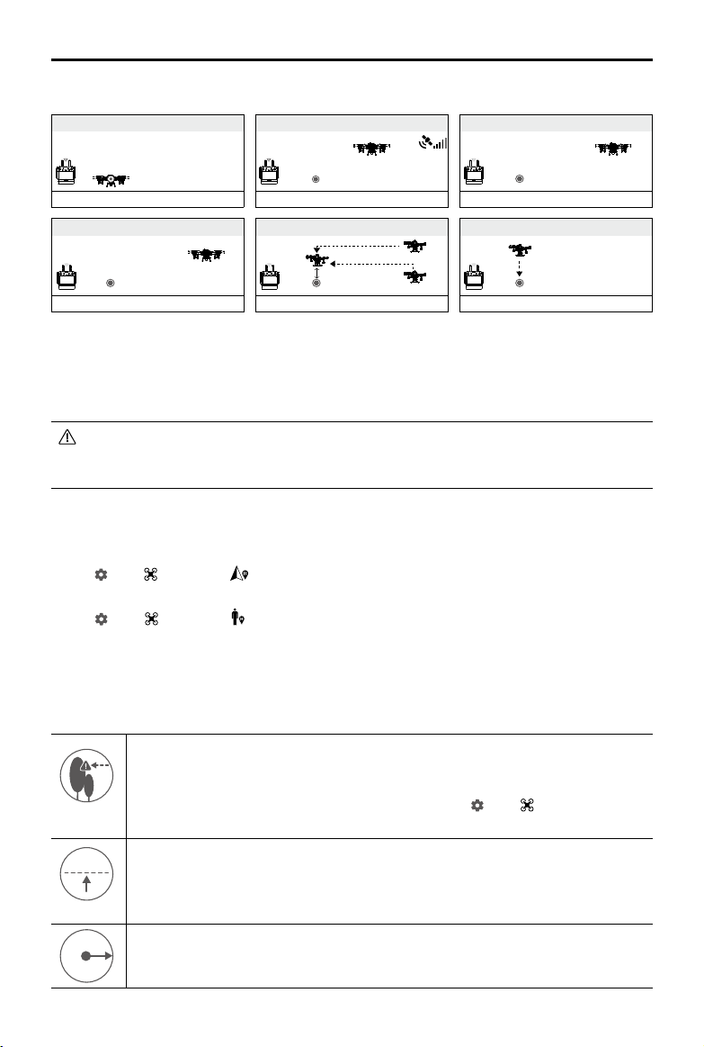
RTH Illustration
1. Record Home Point (HP)
2. Conrm Home Point
AGRAS T20
3. Remote controller signal lost
User Manual
Aircraft blinks green slowly
4.
RTH initiated if signal lost > 3 s
Aircraft blinks yellow quickly
Aircraft blinks green six times
5. RTH initiated (height 15 m (customizable))
Height over HP > 15 m
Elevate to 15 m
15 m
Blinks green slowly
Height over HP ≤ 15 m
Aircraft blinks yellow quickly
6. Lands after hovering for 5 s
Blinks green slowly
Updating the Home Point
You can update the home point in DJI Agras during ight. There are two ways to set a home point:
1. Set the current coordinates of the aircraft as the home point.
2. Set the current coordinates of the remote controller as the home point.
Make sure the space above the remote controller’s GNSS module (located inside the place above
the ight switch mode) is not obstructed and that there are no tall buildings around when updating
the home point.
Follow the instructions below to update the home point:
1. Go to DJI Agras and enter Operation View.
2. Tap
, then , and select in Home Point Location settings to set the current coordinates of the
aircraft as the home point.
3. Tap
, then , and select in Home Point Location settings to set the current coordinates of the
remote controller as the home point.
4. The aircraft status indicators blink green to indicate that the new home point has been set
successfully.
RTH Safety Notices
3 m
5 m
The aircraft cannot avoid obstacles during RTH if the operating environment is not
suitable for the radar module. Users can only control the speed and altitude of the
aircraft. Before each ight, it is important to set an RTH altitude that is appropriate for the
given environment. Go to Operation View in the app, tap , then , and Set Return to
Home Altitude.
If the aircraft is flying under 3 m and RTH (including Smart and Failsafe RTH) is
triggered, the aircraft rst automatically ascends to 3 m from the current altitude. You
cannot control the aircraft during this ascent. In Smart RTH, you can exit RTH to cancel
automatic ascent by pressing the RTH button once.
The aircraft automatically descends and lands if RTH is triggered when the aircraft ies
H
within a 5 m radius of the Home Point.
2020 DJI All Rights Reserved.
©
27
Page 30

AGRAS T20
User Manual
The aircraft cannot return to the home point when the GNSS signal is weak (the GNSS
icon displays red) or is unavailable.
When the RTH altitude is set to more than 3 m and the aircraft is ascending between 3 m
and the preset RTH altitude, the aircraft stops ascending and immediately return to the
home point if the throttle stick is pushed.
Obstacle Avoidance During RTH
In an optimal operating environment, obstacle avoidance during RTH is available. If there is an obstacle
within 20 m of the aircraft, the aircraft decelerates and then stops and hovers. If the aircraft comes within
6 m of the obstacle while decelerating, the aircraft stops, ies backward to a distance of approximately 6
m from the obstacle, and hovers. The aircraft exits the RTH procedure and waits for further commands.
Landing Protection Function
Landing Protection activates during auto landing. The procedure is as follows:
1. After arriving at the home point, the aircraft descends to a position 3 m above the ground and hovers.
2. Control the pitch and roll sticks to adjust the aircraft position and make sure the ground is suitable for
landing.
3. Pull down the throttle stick or follow the onscreen instructions in the app to land the aircraft.
Low Battery and Low Voltage Warnings
The aircraft features a low battery warning, critical low battery warning, and critical low voltage warning.
1. Low Battery Warning: The aircraft status indicators slowly blink red. Fly the aircraft to a safe area and
land it as soon as possible, stop the motors, and replace the batteries.
2. Critical Battery Warning or Critical Voltage Warning (the battery voltage is lower than 47.6 V): the
aircraft status indicators rapidly blink red. The aircraft begins to descend and land automatically.
Users can set the threshold of low battery warnings in the app.
RTK Functions
The T20 has an onboard D-RTK. The heading reference of the aircraft from the dual antennas of the
onboard D-RTK is more accurate than a standard compass sensor and can withstand magnetic
interference from metal structures and high-voltage power lines. When there is a strong GNSS signal,
the dual antennas activates automatically to measure the heading of the aircraft.
The T20 supports centimeter-level positioning to improve agricultural operation when used with the DJI
D-RTK 2 Mobile Station. Follow the instructions below to use the RTK functions.
Enable/Disable RTK
Before each use, make sure that the aircraft RTK positioning function is enabled and the RTK signal
source is correctly set to either D-RTK 2 Mobile Station or Network RTK. Otherwise, RTK cannot be used
2020 DJI All Rights Reserved.
©
28
Page 31

AGRAS T20
for positioning. Go to Operation View in the app, tap , and select RTK to view and set.
Make sure to disable the aircraft RTK positioning function if not in use. Otherwise, the aircraft is not able
to take off when there is no differential data.
User Manual
Using with the DJI D-RTK 2 Mobile Station
1. Refer to the D-RTK 2 Mobile Station User Guide for more information about completing the linking
between the aircraft and the mobile station and setting up the mobile station.
2. Power on the mobile station and wait for the system to start searching for satellites. The RTK status
icon on top of the Operation View in the app shows
used the differential data from the mobile station.
to indicate that the aircraft has obtained and
Using with the Network RTK Service
The Network RTK service uses the remote controller instead of the base station to connect to an
approved Network RTK server for differential data. Keep the remote controller on and connected to the
internet when using this function.
1. Make sure that the remote controller is connected to the aircraft and has access to the internet.
2. Go to Operation View in the app, tap
RTK, and input the network information.
3. Wait for the remote controller to be connected with the Network RTK server. The RTK status icon on
top of the Operation View in the app shows
RTK data from the server.
, and then RTK. Set the RTK signal source to Custom Network
to indicate that the aircraft has obtained and used the
Aircraft LEDs
There are LEDs on all of the frame arms marked M1 to M6. The LEDs on frame arms M1, M2, and M6
are front LEDs, indicating the aircraft front. The LEDs on frame arms M3 and M5 are aircraft status LEDs,
indicating the status of the aircraft. Refer to Appendix (p. 52) for more information on aircraft statuses.
The LEDs on the M4 frame arm constantly glows solid red so the aircraft can be easily identied during
night operations.
M2
M3
M1
M4
M6
M5
2020 DJI All Rights Reserved.
©
29
Page 32

Remote Controller
Prole
The remote controller uses the DJI OcuSync 2.0 image transmission system, which has a maximum
control distance of up to 1.86 mi (3 km). It includes a dedicated, Android-based display that runs DJI
Agras independently for operation planning and aircraft status display. Its Multi-Aircraft Control mode
(supported later) can be used to coordinate the operation of up to ve aircraft at the same time to
improve operation efciency.
Using the Remote Controller
Powering the Remote Controller On and Off
Both the internal battery and external battery can be used to supply power to the remote controller. The
battery level is indicated via the battery level LEDs on the remote controller or on the external battery.
Follow the steps below to power on the remote controller:
1. When the remote controller is powered off, press the power button
once to check the current battery level of the internal battery. Press
the battery level button on the external battery to check the current
battery level of the external battery. If the battery level is too low,
recharge before use.
2. Press the power button once, then press and hold to power on the
remote controller.
3. The remote controller beeps when powered on. The status LED
glows solid green when linking is complete.
4. Repeat Step 2 to power off the remote controller.
When using an external Intelligent Battery, it is still necessary to make sure that the internal
battery has some power. Otherwise, the remote controller cannot be powered on.
Charging the Batteries
Internal Battery
Charge the internal battery of the remote controller using the USB charger and USB-C cable.
Power Outlet
(100 - 240 V)
Use an ofcial DJI USB charger to charge the remote controller. If not, a USB charger certied
FCC/CE rated 12 V/2 A is recommended.
The battery will deplete when stored for an extended period of time. Recharge the battery at
least once every three months to prevent over discharging.
2020 DJI All Rights Reserved.
©
30
USB Charger
Page 33

AGRAS T20
The battery level LEDs on the remote controller indicates the status while charging. See the table below
for details.
User Manual
LEDs Description
Blink successively quickly The battery is being charged using a Quick Charge charger.
Blink successively slowly The battery is being charged using a normal charger.
Solid The battery is fully charged.
External Battery
Charge the external Intelligent Battery using the included AC power adapter and charging hub.
1. Place the battery into the charging hub, connect the AC power adapter to the charging hub, and
connect the charger to a power outlet (100-240 V, 50/60 Hz).
2. The charging hub automatically charges batteries in order according to the battery power levels from
high to low.
3. The Status LED blinks green when charging and turns solid green when fully charged. The charging
hub beeps when charging is complete. To stop the beeping, remove the battery or turn off the button
on the charging hub.
Power Outlet
AC Power AdapterCharging Hub
Fully charge and discharge the battery at least once every three month.
USB power supply port can be used to charge the mobile device of 5V/2A.
Status LED Description
Blinks Green Charging
Solid Green Fully charged
Blinks Red Battery charger error. Retry with an ofcial battery charger
Solid Red Battery error
Blinks Yellow Battery temperature too high/low. Temperature must be within
operating range (5°to 40°C (41°to 104° F))
Solid Yellow Ready to charge
Blinks Green Alternately Intelligent Battery not detected
2020 DJI All Rights Reserved.
©
31
Page 34

AGRAS T20
User Manual
Operating the Aircraft
This section explains how to control the orientation of the aircraft through the remote controller. Control
can be set to Mode 1, Mode 2, or Mode 3.
Mode 1
Mode 2
Mode 3
Left Stick
Forward
Backward
Turn RightTurn Left
Right Stick
Right StickLeft Stick
UP
Down
Turn RightTurn Left
Left Stick Right Stick
Forward
UP
Down
RightLeft
Forward
Backward
RightLeft
UP
2020 DJI All Rights Reserved.
©
32
Backward
Down
RightLeft
Turn RightTurn Left
Page 35

For example, the following description uses Mode 2:
AGRAS T20
User Manual
Remote Controller
(Mode 2)
Aircraft ( Indicates nose
direction)
Remarks
Throttle Stick: Move the left stick vertically to
control the elevation of the aircraft.
Push up to ascend and push down to
descend. Use the left stick to take off when
the motors are spinning at an idle speed.
The aircraft hovers in place if the stick is in
the center position. The further the stick is
pushed away from the center position, the
faster the aircraft changes elevation.
Yaw Stick: Move the left stick horizontally to
control the heading of the aircraft.
Push left to rotate the aircraft counterclockwise
and push right to rotate clockwise. The aircraft
hovers in place if the stick is in the center
position. The further the stick is pushed away
from the center position, the faster the aircraft
rotates.
Pitch Stick: Move the right stick vertically to
control the pitch of the aircraft.
Push up to y forwards and press down to y
backwards. The aircraft hovers in place if the
stick is in the center position. Push the stick
further for a larger pitch angle and faster
ight.
Roll Stick: Move the right control stick
horizontally to control the roll of the aircraft.
Push the stick left to fly left and right to fly
right. The aircraft hovers in place if the stick
is in the central position. Push the stick
further for a larger roll angle and faster ight.
2020 DJI All Rights Reserved.
©
33
Page 36

AGRAS T20
User Manual
Controlling the Spraying System
Complete an operation remotely via the spray rate or aircraft control switch dials, or the spray and C1 or
C2 buttons.
56
1
2
4
3
1. Spray Rate Dial
In Manual operation mode, turn left to reduce and right to increase the spray rate.* The app indicates
the current spray rate.
2. Spray Button
In Manual operation mode, press to start or stop spraying.
3. FPV / Map Switch Button
In Operation View in DJI Agras, press to switch between FPV and the Map View.
4. Aircraft Control Switch Dial
Turn the dial to switch among the aircraft when using Multi-Aircraft Control function.
5. Button C1
When planning a eld, press the button to switch between Obstacle mode and Waypoints mode. The
function of the button cannot be customized while planning a eld.
When not planning a field, use the app to customize the button. For example, if the button is
customized to record Point A, in A-B Route operations, press the button to record Point A of the
operation route.
6. Button C2
When planning a eld, press the button to add a waypoint or an obstacle point. The function of the
button cannot be customized when planning a eld.
When not planning a field, use the app to customize the button. For example, if the button is
customized to record Point B, in A-B Route operations, press the button to record Point B of the
operation route.
* Spray rate may vary according to the nozzle model and viscosity of the liquid.
2020 DJI All Rights Reserved.
©
34
Page 37

AGRAS T20
位置P
位置P
位置A
User Manual
The table below is a summary for how to control the spraying system in different modes using the remote
controller.
Modes Spray Rate Dial Spray Button
Route operation
mode
A-B Route
operation mode
Manual operation
mode
Manual Plus
operation mode
Field Planning / / / /
/ / Switch the display
/ / Switch the display / Customizable Customizable
Adjust spray rate
Adjust spray rate / Switch the display / Customizable Customizable
Start or stop
spraying
FPV / Map Switch
Button
Switch the display / Customizable Customizable
Aircraft Control
Switch Dial
Switch between
aircraft
Button C1 Button C2
Customizable Customizable
Obstacle mode/
Waypoint mode
Add waypoint/
obstacle point
Flight Mode Switch
Position P
Position A
Position P
Position Flight Mode
P
P-mode (Positioning)
A
A-mode (Attitude)
P
P-mode (Positioning)
Regardless of the position the switch is in on the remote controller, the aircraft begins in P-mode by
default. To switch ight modes, rst go to Operation View in DJI Agras, tap , then , and enable
“Enable Attitude Mode”. After enabling attitude mode, toggle the switch to P and then to A to switch the
ight mode to Attitude mode.
The aircraft still begins in P-mode by default after powering on, even though A-mode was enabled in
the app beforehand. When A-mode is required, toggle the Flight Mode switch as mentioned above after
powering on the remote controller and aircraft.
RTH Button
Press and hold the RTH button to bring the aircraft back to the last recorded home point. The LED
around the RTH Button blinks white during RTH. Users can control aircraft heading while it ies to the
home point. Press this button again to cancel RTH and regain control of the aircraft.
2020 DJI All Rights Reserved.
©
35
Page 38

AGRAS T20
11:3011:30
User Manual
Optimal Transmission Zone
When the angle between the antennas and the back of the remote controller is 80° or 180°, the
connection between the remote controller and aircraft can reach its optimal performance.
80°
Try to keep the aircraft inside the optimal transmission zone. If the signal is weak, adjust the antennas or
y the aircraft closer.
Button Combinations
Some frequently-used features can be activated by using button combinations. To use button
combinations, hold the back button and then press the other button.
Checking the Available Button Combinations
Hold the Back button until the controller vibrates to check button combinations:
50%
100%
Press and then the corresponding button to perform an operation.
Brightness Mode
Screen Recording
Home
Recent Apps
Quick Settings
Button Combinations
Adjust Volume
Screenshot
Using Button Combinations
The functions of the button combinations cannot be changed. The following table displays the function
of each button combination.
2020 DJI All Rights Reserved.
©
36
Page 39

AGRAS T20
Button Combinations Description
Function Button + Aircraft Control Switch Dial
(Right Dial)
Function Button + Spray Rate Dial (Left Dial) Adjust the screen brightness
Function Button + Spray Button Record the screen
Function Button + FPV / Map Switch Button Screenshot the screen
Function Button + 5D Button (up) Return to Homepage
Function Button + 5D Button (down) Open Quick Settings
Function Button + 5D Button (left) Check recently opened apps
Function Button + 5D Button (right) Open App Center
Adjust the system volume
User Manual
Calibrating the Compass
After the remote controller is used in places with electro-magnetic interference, the compass may need
to be calibrated. A warning prompt will appear if the remote controller’s compass requires calibration.
Tap the warning prompt to start calibrating. In other cases, follow the steps below to calibrate your
remote controller.
1. Power on the remote controller.
2. Swipe down from the top of the screen, tap
3. Follow the diagram on the screen to calibrate your remote controller.
4. The user will receive a prompt when the calibration is successful.
, and scroll down and tap Compass.
Blocking Third-Party Notications
To ensure safe ight, it is recommended to disable third-party notications before each ight. Follow the
steps below to disable third-party notications.
Power on the remote controller. Swipe down from the top of the screen, tap
enable Do Not Disturb. After this, all the third-party notications will be displayed in the notication bar
only when the DJI Agras app is in use.
, then Notications, and
Remote Controller LEDs
Status LED
The battery level indicators display the battery level of the controller. The status LED displays the linking
status and warnings for control stick, low battery level, and high temperature.
Battery Level Indicators
2020 DJI All Rights Reserved.
©
37
Page 40

AGRAS T20
User Manual
Status LED Description
Solid Red The remote controller is not linked to an aircraft.
Solid Green The remote controller is linked to an aircraft.
Blinks Blue The remote controller is linking to an aircraft.
Blinks Red
Blinks Yellow The battery level of the remote controller is low.
Blinks Cyan The control sticks are not centered.
Battery Level Indicators Battery Level
75%~100%
50%~75%
25%~50%
0%~25%
The temperature of the remote controller is too high or the battery
level of the aircraft is low.
Remote Controller Warning Sounds
In scenarios where there is a warning, the remote controller will do so by vibrating and/or beeping. When
the controller beeps and the status LED is solid green, this error may be related to the aircraft or ight
status, and a warning will appear in DJI Agras. If this error is related to the remote controller, a warning
will appear on the screen of the remote controller.
To disable the beeping, power on the remote controller, swipe from the top of the screen, tap
Sound, and adjust the notication volume.
, then
Linking the Remote Controller
The remote controller is linked to the aircraft by default. Linking is only required when using a new
remote controller for the rst time. When using the Multi-Aircraft Control function, it is required to link all
aircraft to the same remote controller.
1. Power on the remote controller and open DJI Agras. Power on the aircraft.
2. Tap Execute Operation to enter Operation View and tap
Linking (if Multi-Aircraft Control is in use), and then tap Starting Linking. The status LED blinks blue
and the remote controller beeps twice repeatedly, indicating that the remote controller is ready for
linking.
3. Press and hold the power button on the Intelligent Flight Battery for ve seconds. The aircraft front
LEDs blink red and green alternately, indicating that the linking is in progress.
4. The Status LED on the remote controller glows solid green and the aircraft front LEDs blinks red
several times if linking is successful. If linking fails, enter linking status again and retry.
5. Repeat Step 3 and 4 to complete linking between all the devices and the remote controller, if Multi
Linking is selected. When nished, tap End Linking. Note that up to ve devices can be linked.
2020 DJI All Rights Reserved.
©
38
, then . Tap Single Linking or Multi
Page 41

DJI Agras App
11:22
DJI Agras is designed for agricultural applications. The app has a clear and concise interface and
displays the status of the aircraft, spraying system, and other devices connected to the remote
controller, and enables users to configure various settings. After planning a field via the intelligent
operation planning system of the app, the aircraft can automatically follow the pre-planned ight route.
Home Screen
1 2 3 64 75 8 9
93
25
New firmware
10
11
Aircraft connected
Plan a Field Execute Operation
12
1. Task Management
: View planned elds and operation progress. You can synchronize the local data with the data on
the DJI AG platform.
2. User Info
: View account information.
3. Aircraft Info
: View the information of the connected aircraft such as the rmware version.
4. Troubleshooting
: View solutions for errors of each module and upload error logs.
5. General Settings
: Tap for settings such as units of measurement, network diagnosis, and Android system settings.
6. Expansion Module Connection Status
: Shows if the remote controller expansion module (used to mount the 4G dongle) is connected.
7. 4G Dongle Signal Strength
: The icon is displayed if a 4G dongle is mounted. It shows the current signal strength of the 4G
dongle.
2020 DJI All Rights Reserved.
©
39
Page 42

AGRAS T20
5M
10M
15M
N
S
W
E
User Manual
8. External Battery Level
: The icon is displayed if an external battery is mounted. It shows the current battery level
25
of the external battery.
9. Internal Battery Level
: Shows the current battery level of the internal battery.
93
10. Firmware Notications
: Shows the rmware update notications. Tap to enter the rmware page.
11. Aircraft Connection Status
: Shows if the aircraft is connected to the remote controller.
12. Plan a Field | Execute Operation
Plan a Field: Tap the button and select the planning method to plan a eld.
Execute Operation: Tap to enter Operation View to view the aircraft status, congure settings, and
switch between different operation modes.
Operation View
21 3 4 5 19 20 21 22 23 24
Route (GNSS)
FIX
6
7
8
9
10
11
12
13
RTK
Parameters
Configuration
1.0 3.4
Sprayed
1.9
DISTANCE
M L/MIN
85.8
HEIGHT SPEED REMAINING
M M/S L
0.8 0.8 0.8
Altitude
Stabilization
HA
FLOW
0.0
%
99
ML/HA
14.5M
14.5M
14.5M
14.5M
14.5M
14.5M
14.5M
4.5M
18
17
16
Start
15
14
1. System Status
Route (GNSS)
Aircraft Health System to view and diagnose each module and upload status logs.
2. RTK/GNSS Signal Strength
FIX
: This icon is displayed when RTK is enabled and works normally. On the upper right corner is
RTK
the number of satellites connected. One of the following three statuses is displayed above the RTK
icon: FIX indicates that the differential data calculation is completed and the aircraft can use RTK for
positioning. The aircraft can only take off in this status. FLOAT indicates that the system is calculating
the differential data. Wait for FIX to be displayed. SINGLE indicates that the differential data is not
obtained. Wait for FIX to be displayed.
2020 DJI All Rights Reserved.
©
40
: Indicates current ight modes, operation modes, and warning messages. Tap to enter
Page 43

AGRAS T20
: This icon is displayed when RTK is not in use. It shows the current GNSS signal strength and
the number of satellites connected.
3. RTK Connection Status
Icons displayed when using RTK data. The display varies when using the D-RTK 2 or Network RTK
Service.
: Displays RTK signal strength when using the D-RTK 2.
: Indicates that the connection with the D-RTK 2 is abnormal. Refer to the prompts in the app.
: Displays RTK signal strength when using the Network RTK Service.
: Indicates that the connection with the Network RTK server is abnormal. Refer to the prompts in
the app.
4. Control Signal Strength
: Shows the signal strength of the connection between the aircraft and the remote controller.
5. Battery Settings
6. Altitude Stabilization
When the altitude stabilization function of the radar module is enabled, this icon shows the preset
7. Parameters Conguration
Shows the spray amount. Tap the value to enter the menu for operation parameters adjustment. The
: Shows the current battery level. Tap to set the low battery warning threshold and view
battery information.
height between the aircraft and the object underneath the aircraft. Tap the value to adjust.
adjustable parameters vary according to the operation mode, including spray amount, ying speed,
line spacing, height above the vegetation, and banked turning.
User Manual
8. Radar Working Mode
Shows the current working mode of the radar module. Tap to select.
: Obstacle Avoidance Radar indicates that obstacle avoidance is enabled.
: Narrow Radar indicates that the radar detection angle is narrower than usual to allow ying
close to the edges of elds. For example, when there are eld boundaries such as fences or trees,
enable Narrow Radar mode to make sure that the aircraft can y closer to the edges and spray liquid
on the vegetation near the edges.
: Disable Radar indicates that the obstacle avoidance function is disabled. This will not disable
the altitude stabilization function of the radar module.
9. Area
Shows the area values related to the operation area, including the following values.
Field Area: Shows the total plan area value when planning fields for Route operations via the
intelligent operation planning system.
Plan Area: Shows the value of the actual area of the planned ight route after planning elds. The
area is planned using the following formula: Plan Area = Field Area - Obstacle Area - Safety Margin
Zone.
2020 DJI All Rights Reserved.
©
41
Page 44

AGRAS T20
Obstacle Area: Shows the area value of the obstacles measured when planning fields for Route
Safety Margin Area: Shows the area of the safety margin zone if the safety margin is congured when
Sprayed Area: Shows the value of the area already sprayed.
10. Operation List
11. Operation Mode Switch Button
12. Flight Telemetry
Distance: Horizontal distance from the aircraft to the home point.
Flow: Pesticide ow rate.
Height: When the altitude stabilization function of the radar module is enabled, it shows the preset
Speed: The ying speed of the aircraft.
Remaining: The remaining amount of pesticide.
13. Liquid Level Notication
It shows a full green progress bar when the remaining liquid amount in the spray tank is sufcient.
User Manual
operations.
planning elds for Route operations.
: Displayed in M operation mode. Tap to view the planned elds and operations in progress and
invoke operations.
/ / : Tap to switch between Manual (M), Manual Plus (M+), and A-B Route (AB) operation
modes.
height between the aircraft and the object underneath the aircraft. Otherwise, it shows the height
between the aircraft and the takeoff point.
When the remaining liquid level nears the threshold of the empty tank warning, the green part of the
progress bar will start to reduce gradually. It will turn gray when the remaining liquid level reaches
the empty tank warning.
14. Home Screen
: Tap this icon to return to the home screen.
15. Operation Control Buttons
Used to control the aircraft during different operation types, including measuring an operation area
and invoking, starting, pausing, or ending an operation.
16. FPV Camera View
Displays the real-time image from the FPV camera. Tap to switch between the Map View and the
Camera View.
17. Obstacle Detection Status
Shows information on the detected obstacles when the obstacle avoidance function of the radar
module is enabled. The information of obstacles in all horizontal directions will display on the screen
in the shape of a circle. Red bars indicate obstacles nearby, while yellow bars indicate obstacles
further away. The value indicates the distance between the aircraft and the nearest obstacle.
2020 DJI All Rights Reserved.
©
42
Page 45

AGRAS T20
18. Obstacle Radar Map
During Route or A-B Route operations, the icon shows the nearby obstacles and planned ight
route using the auto obstacle avoidance function, if obstacles are detected when auto obstacle
avoidance is enabled.
19. FPV Mode Switch
Tap to switch the FPV display mode. If Night mode is selected, the image display will be brighter. If
Day mode is selected, the image display will be normal.
20. Clear Screen
: Tap to clear the ight route currently shown on the map.
21. Location
: Tap to center the map around the location of the aircraft or the latest recorded home point.
22. Location Follow
Tap to choose if the map display follows the aircraft location.
: To keep the aircraft centered in the map.
: To keep the map display xed regardless of the aircraft location.
23. Map Mode
: Tap to switch between Standard, Satellite, or Night modes.
24. More Settings
Tap
to enter the extended menu to view and adjust the parameters of all other settings.
: Aircraft Settings - Includes setting the action after completing spraying and completing
operations, the aircraft behavior and whether to abort operation when the remote controller signal is
lost, home point position, RTH altitude, lamp brightness, whether to lock the heading in Manual Plus
operation mode, whether to enable Attitude mode, maximum altitude, and maximum ight distance
limit, and advanced settings.
: Spraying System Settings - Includes setting whether to display real-time data, to clear trapped
air, setting spray tank level, empty tank warning threshold, whether to display pesticide placement
point, and ow meter error alert, calibrating pump ow and ow meter, nozzle model, and to restore
ow meter to factory settings.
: RC Settings - Includes linking, linked aircraft, RC calibration, stick mode, RC custom key, and
RC ID.
: Radar Settings - Includes altitude stabilization, obstacle avoidance, narrow radar mode,
spraying terrain (Flat and Mountain), and obstacle display mode.
: RTK Settings - Includes aircraft RTK positioning, RTK signal source and the corresponding
settings.
: Image Transfer Settings - Includes channel mode and sweep frequency chart selection.
: Aircraft Battery - Includes low battery warning and battery information.
: General Settings - Includes map settings, ight route display, and FPV settings.
User Manual
2020 DJI All Rights Reserved.
©
43
Page 46

Flight
Operation Environment
1. DO NOT use the aircraft to spray in winds exceeding 18 kph (11 mph).
2. DO NOT use the aircraft in adverse weather conditions such as snow, fog, winds exceeding
28 kph (17 mph), and heavy rain (precipitation rate exceeding 25 mm (0.98 in) in 12 hours).
3. Only y in open areas. Tall buildings and steel structures may affect the accuracy of the compass
and the GNSS signal.
4. Pay attention to utility poles, power lines, and other obstacles. DO NOT fly near or above water,
people, or animals.
5. Maintain VLOS of the aircraft at all times, and avoid flying near obstacles, crowds, animals, and
bodies of water.
6. Avoid ying in areas with high levels of electromagnetism, including mobile phone base stations and
radio transmission towers.
7. The recommended maximum operating altitude is 2 km (6,560 ft) above sea level. DO NOT y over 3
km (9,842 ft) above sea level.
8. Once the operating altitude reaches 1 km (3,280 ft), the payload capacity of the spray tank is
reduced by 2 kg. For every additional km, the payload capacity will reduce by a further 2 kg.
9. Make sure that there is a strong GNSS signal and the D-RTK antennas are unobstructed during
operation.
10. DO NOT operate the aircraft indoors.
Flight Limits and GEO Zones
Unmanned aerial vehicle (UAV) operators should abide by the regulations from self-regulatory
organizations such as the International Civil Aviation Organization, the Federal Aviation Administration,
and their local aviation authorities. For safety reasons, ight limits are enabled by default to help users
operate this aircraft safely and legally. Users can set ight limits on height and distance.
When operating with a strong GNSS signal, the height and distance limits and GEO zones work together
to monitor ight. With a weak GNSS signal, only the height limit prevents the aircraft from going above 30
meters.
Maximum Height and Radius Limits
Users can change the maximum height and radius limits in the app. Once completed, the aircraft ight
is restricted to a cylindrical area that is determined by these settings. The tables below show the details
of these limits.
Max Flight Altitude
Max Radius
Home Point
Altitude of aircraft when powered on or the
2020 DJI All Rights Reserved.
©
44
distance of the aircraft to the surface
Page 47

AGRAS T20
Restricted Zone Free Zone
Restricted Zone
User Manual
With a strong GNSS signal
Flight Limits
Max Height Flight altitude must be below the preset height.
Max Radius Flight distance must be within the max radius.
With a weak GNSS signal
Flight Limits
Max Height Flight altitude must be below the preset height.
Max Radius No limit.
If the aircraft ies into a Restricted Zone, it can still be controlled, but the aircraft can only y in
a backward direction.
If the aircraft loses GNSS signal and ies out of the max radius but regains GNSS signal later,
it will y back within range automatically.
GEO Zones
GEO zones are divided into different categories. All GEO zones are listed on the DJI ofcial website at
http://www.dji.com/ysafe.
GEO zones are explained below (GNSS required):
Depending on the local regulation, a certain radius around a marker forms a Restricted Zone, inside of
which takeoff and ight are prohibited.
R
2020 DJI All Rights Reserved.
©
45
Page 48

AGRAS T20
With a strong GNSS signal
Restrictions
User Manual
Area Restriction Aircraft Status Indicators
Restricted
Zone
No Flight
Semi-Automatic Descent: All stick commands except the throttle stick command are available
during descent and landing. Motors automatically stop after landing.
When operating in Restricted Zones, the aircraft status indicators blink red slowly and
continue for ve seconds, and then switch to the current aircraft status for twelve seconds. If
the aircraft is still in the Restricted Zone at that point, it switches to blinking red slowly for ve
seconds again and so on.
DO NOT y near airports, highways, railway stations, railway lines, city centers, or other busy
areas. Make sure the aircraft is visible at all times.
Motors will not start.
If the aircraft loses GNSS signal and enters a
Restricted Zone but regains GNSS signal later, the
aircraft will enter semi-automatic descent and land.
Users can y their aircraft freely. None.
Blink Red
Pre-Flight Checklist
1. Make sure the remote controller and aircraft battery are fully charged. The pesticides required are
adequate.
2. Make sure the spray tank and Intelligent Flight Battery are rmly in place.
3. Make sure all parts are mounted securely.
4. Make sure all cables are connected properly and rmly.
5. Make sure propellers are securely mounted, that there are no foreign objects in or on the motors and
propellers, that the propeller blades and arms are unfolded, and the arm sleeves are rmly tightened.
6. Make sure the spraying system is not blocked in any way.
7. Make sure the sprinkler hoses are clear from bubbles. Discharge any bubbles as they may affect the
performance of the sprinkler. Press and hold the spray button for two seconds to start the automatic
bubbles discharge function to spray the bubbles.
Calibrating the Spraying System
Make sure to calibrate the ow meter before your rst operation. Otherwise, the spraying performance
may be adversely affected.
1. Preparation before calibration: Discharging the bubbles in the hoses
1
Fill the spray tank with approximately 2 L of water.
2
Use the automatic bubbles discharge function to discharge the bubbles according to the
descriptions in the Discharging the Bubbles in the Hoses section below. Users can also manually
2020 DJI All Rights Reserved.
©
46
Page 49
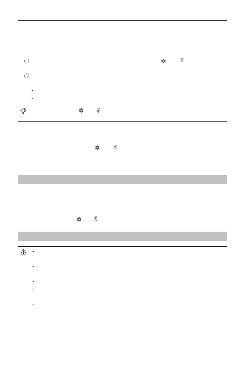
AGRAS T20
discharge the bubbles. Press the spray button to spray the bubbles and press the button again
once all bubbles are discharged.
2. Flow Meter Calibration
1
In the app, tap Execute Operation to enter Operation View. Tap , then , and tap Calibration
on the right of the ow meter section.
2
Calibration starts automatically. After 25 seconds, the result of the calibration is displayed in the
app.
After calibrating successfully, users can proceed with the operation.
If calibration fails, tap “?” to view and resolve the problem. Afterward, recalibrate.
During calibration, tap , then to cancel. If the calibration is cancelled, the accuracy of the
ow meter is based on the data before the calibration was started.
User Manual
When to Recalibrate
1. Installing a different nozzle model. Note: Choose the corresponding model in the app after replacing
nozzles. Go to Operation View, tap
2. Using a liquid of a different viscosity.
3. The error between the actual value and the theoretical value of the completed area is more than 15%.
, then for conguration.
Discharging the Bubbles in the Hoses
The T20 features an automatic bubbles discharge function. When it is necessary to discharge bubbles,
start the function through one of the two methods below. The aircraft will discharge automatically until
the bubbles are fully discharged.
1. Press and hold the spray button for two seconds.
2. Enter Operation View, tap
, then , and tap Start on the right of the Clear Trapped Air section.
Calibrating the Compass
It is important to calibrate the compass. The calibration result affects the ight safety. The
aircraft may malfunction if the compass is not calibrated.
DO NOT calibrate the compass where there is a chance of strong magnetic interference. This
includes areas where there are utility poles or walls with steel reinforcements.
DO NOT carry ferromagnetic materials with you during calibration such as keys or mobile phones.
If the aircraft status indicators show a blinking red light, compass calibration has failed. Please
recalibrate.
After calibrating successfully, the compass may be abnormal when you place the aircraft on
the ground. This may be because of underground magnetic interference underground. Move
the aircraft to another location and try again.
2020 DJI All Rights Reserved.
©
47
Page 50

AGRAS T20
Calibrate the compass when prompted by the app. It is recommended to calibrate the compass with an
empty tank
1. Tap
2. Hold the aircraft horizontally and rotate it 360° around a vertical axis with the aircraft approximately 1.2
3. If the app displays a tilted aircraft, it indicates that the horizontal calibration failed. Users should tilt
User Manual
, then , move the slider to the bottom, and select Advanced Settings, then IMU and
Compass Calibration. Tap Calibration in the compass calibration section.
m above the ground. Calibration is completed when the app displays that calibration was successful.
the aircraft and rotate it horizontally. Calibration is completed when the app displays that calibration
was successful. To reduce the number of rotations required, the aircraft should be tilted at least 45°.
4. If calibration continues to fail, recalibrate the compass from Step 1.
2020 DJI All Rights Reserved.
©
48
Page 51

AGRAS T20
User Manual
Starting and Stopping the Motors
Starting the Motors
The Combination Stick Command (CSC) listed below is used to start and stop the motors. Make sure
you perform the CSC in one continuous motion. The motors begin to accelerate at an idle speed.
Release both sticks simultaneously. Take off immediately once the motors are spinning, or else the
aircraft may lose balance, drift, or even takeoff by itself and risk causing damage or injury.
OR
Stopping the Motors
There are two methods to stop the motors.
1. When the aircraft has landed, push and hold the throttle stick down. The motors will stop after three
seconds.
Throttle Stick (left stick in Mode 2)
2. When the aircraft has landed, push the throttle stick down, and perform the same CSC that was used
to start the motors. Release both sticks once the motors have stopped. Release both sticks once the
motors have stopped.
OR
Throttle Stick
Spinning propellers can be dangerous. Stay away from spinning propellers and motors. DO
NOT start the motors in conned spaces or when there are people nearby.
Keep your hands on the remote controller when the motors are spinning.
DO NOT stop the motors mid-flight unless in an emergency situation where doing so will
reduce the risk of damage or injury.
Method 1 is the recommended method for stopping the motors. When using Method 2 to
stop the motors, the aircraft may roll over if it is not completely grounded. Use Method 2 with
caution.
After landing, power off the aircraft before powering off the remote controller.
2020 DJI All Rights Reserved.
©
49
Page 52

AGRAS T20
User Manual
Flight Test
1. Place the aircraft on open, at ground with the aircraft status indicators facing toward you.
2. Pour liquid into the spray tank, and tighten the cover. Make sure that the four lines on the cover are
aligned to the horizontal or vertical direction.
3. Power on the remote controller, make sure that DJI Agras is open, and then power on the aircraft.
4. Make sure that the aircraft is connected to the remote controller.
5. If using RTK for positioning, make sure that the aircraft RTK positioning function is enabled and RTK
signal source is correctly set (D-RTK 2 Mobile Station or Network RTK service). Go to Operation View
in the app, tap
Make sure to disable the aircraft RTK positioning function if it is not in use. Otherwise, the aircraft is
not be able to take off when there is no differential data.
6. Wait for satellites to be searched, make sure that there is a strong GNSS signal, and make sure the
aircraft heading measurement using the dual antennas is ready. Perform the CSC to start the motors.
(If the dual antennas are not ready after waiting for an extended period, move the aircraft to an open
area with a strong GNSS signal.)
7. Push the throttle stick up to take off.
8. Select the desired operation or ight mode and start operation.
9. Exit the operation to manually control the aircraft for landing. Hover over a level surface and gently
pull down on the throttle stick to slowly descend.
10. After landing, push the throttle down and hold. The motors stop after three seconds.
11. Power off the aircraft, and then power off the remote controller.
and select RTK to view and set.
When the aircraft status indicators rapidly blink yellow during ight, the aircraft has entered
Failsafe mode.
The low battery level warning is triggered when the aircraft status indicators slowly blink red.
Fly the aircraft to a safe area and land as soon as possible, stop the motors, and replace the
battery. The critical low battery level warning is triggered when the aircraft status indicators
rapidly blink red. The aircraft will begin to automatically descend and land.
2020 DJI All Rights Reserved.
©
50
Page 53

DJI Assistant 2 for MG
Configure settings of the basic parameters, copy flight records, and update aircraft and remote
controller rmware in DJI Assistant 2 for MG.
Installation and Launching
1. Download the DJI Assistant 2 for MG installation le from the T20 download page:
http://www.dji.com/t20/info#downloads
2. Install the software.
3. Launch DJI Assistant 2 for MG.
Using DJI Assistant 2 for MG
Connecting the Aircraft
Connect the USB-C port on the bottom of the aerial-electronics system of the aircraft to a computer with
a USB-C cable, and then power on the aircraft.
Make sure to remove the propellers before using DJI Assistant 2 for MG.
Remove the waterproof cover on the USB-C port before use. Attach the waterproof cover to the
port after use. Otherwise, water may enter the port, causing it to short circuit.
Firmware Update
A DJI account is required for rmware updates. Login or register an account.
Basic Settings
Congure the idle speed of and test the motor.
Tools
Enter SD card mode and copy the ight record.
Connecting the Remote Controller
1. Connect the USB-C port of the remote controller to a computer with a USB A to A cable, and then
power on the remote controller.
2. Swipe from the top of the screen, and make sure that the USB option is enabled.
Firmware Update
A DJI account is required for rmware updates. Login or register an account.
DO NOT power off the remote controller during the update.
DO NOT perform the rmware update while the aircraft is in the air. Only carry out the rmware
update when the aircraft is on the ground.
The remote controller may become unlinked from the aircraft after the rmware update. Relink
the remote controller and aircraft if necessary.
Data Copy
To copy data, access the internal storage of the remote controller and the inserted microSD
card through the computer.
2020 DJI All Rights Reserved.
©
51
Page 54

Appendix
Specications
Product Model 3WWDZ-15.1B
Airframe
Max Diagonal Wheelbase 1883 mm
Dimensions 2509×2213×732 mm (Arms and propellers unfolded)
Propulsion System
Motors
Stator Size 100×15 mm
KV 75 rpm/V
Max Thrust 13.5 kg/rotor
Max Power 2400 W/rotor
Weight 666 g
ESCs
Max Working Current
(Continuous)
Max Working Voltage 58.8 V (14S LiPo)
Foldable Propellers (R3390)
Diameter × Pitch 33×9 in
Weight (Single propeller) 90 g
Spraying System
Spray Tank
Volume Full: 20 L
Operating Payload Full: 20 kg
Nozzles
Model XR11001VS (Standard); XR110015VS, XR11002VS (Optional, purchase
Quantity 8
Max Spray Rate XR11001VS: 3.6 L/min, XR110015VS: 4.8 L/min, XR11002VS: 6 L/min
Spray Width 4 - 7 m (8 nozzles, at a height of 2 - 3 m above crops)
Droplet Size XR11001VS: 130 - 250 μm, XR110015VS: 170 - 265 μm, XR11002VS: 190 -
Flow Meter
Measurement Range 0.25 - 20 L/min
Error < ±2%
Measurable Liquid Conductivity > 50 μS/cm (Liquids such as tap water or pesticides that contain
1795×1510×732 mm (Arms unfolded and propellers folded)
1100×570×732 mm (Arms and propellers folded)
40 A
separately)
300 μm (Subject to operating environment and spray rate)
water)
2020 DJI All Rights Reserved.
©
52
Page 55

AGRAS T20
Omnidirectional Digital Radar
Model RD2428R
Operating Frequency CE / FCC / NCC: 24.05 - 24.25 GHz
MIC / KCC: 24.05 - 24.25 GHz
Transmitter Power (EIRP) MIC / KCC / CE / FCC / NCC: < 20 dBm
Power Consumption 18 W
Altitude Detection & Terrain
[1]
Follow
Altitude detection range: 1 - 30 m
Stabilization working range: 1.5 - 15 m
Max slope in Mountain mode: 35°
[1]
Obstacle Avoidance System
Obstacle sensing range: 1.5 - 30 m
FOV: Horizontal: 360°, Vertical: ±15°
Working conditions: Flying higher than 1.5 m over the surface below at a
speed lower than 7 m/s
Safety distance: 2.5 m (Distance between the front of propellers and the
obstacle after braking)
Obstacle avoidance direction: Omnidirectional obstacle avoidance in the
horizontal direction
IP Rating IP67
FPV Camera
FOV Horizontal: 98°, Vertical: 78°
Resolution 1280×960 30fps
FPV Spotlight FOV: 110°, Max brightness: 12 lux at 5 m of direct light
Flight Parameters
OcuSync 2.0 Operating
Frequency
[2]
OcuSync 2.0 Transmitter
Power (EIRP)
CE / MIC / KCC / FCC / NCC / SRRC: 2.4000 - 2.4835 GHz
FCC / NCC / SRRC: 5.725 - 5.850 GHz
2.4 GHz
SRRC / CE / MIC / KCC: 18.5 dBm, FCC / NCC: 25.5 dBm
5.8 GHz
SRRC / FCC / NCC: 25.5 dBm
Total Weight (Excluding battery) 21.1 kg
Max Takeo Weight 47.5 kg (At sea level)
Max Thrust-Weight Ratio 1.70 (Takeo weight of 47.5 kg)
Hovering Accuracy Range
(With strong GNSS signal)
D-RTK enabled: Horizontal: ±10 cm, Vertical: ±10 cm
D-RTK disabled:
Horizontal: ±0.6 m, Vertical: ±0.3 m (Radar module enabled: ±0.1 m)
RTK / GNSS Operating
Frequency
RTK: GPS L1/L2, GLONASS F1/F2, BeiDou B1/B2, Galileo E1/E5
GNSS: GPS L1, GLONASS F1, Galileo E1
[3]
Battery DJI-approved ight battery (AB3-18000mAh-51.8V)
Max Power Consumption 8300 W
Hovering Power Consumption 6200 W (Takeo weight of 47.5 kg)
Hovering Time
[4]
15 min (Takeo weight of 27.5 kg with an 18000 mAh battery)
10 min (Takeo weight of 47.5 kg with an 18000 mAh battery)
Max Tilt Angle 15°
Max Operating Speed 7 m/s
User Manual
[3]
2020 DJI All Rights Reserved.
©
53
Page 56

AGRAS T20
User Manual
Max Flying Speed 10 m/s (With a strong GNSS signal)
Max Wind Resistance 8 m/s
Max Service Ceiling Above Sea
Level
Recommended Operating
Temperature
2000 m
0° to 40° C (32° to 104° F)
Remte Controller
Model RM500-AG
2
Screen 5.5-inch screen, 1920×1080, 1000 cd/m
, Android system
RAM 4 GB LPDDR4
ROM 32 GB + scalable storage;
microSD cards supported;
Max Capacity: 128 GB. UHS-I Speed Grade 3 rating required
Built-in Battery 18650 Li-ion (5000 mAh @ 7.2 V)
GNSS GPS+GLONASS
Power Consumption 18 W
Operating Temperature -10° to 40° C (14° to 104° F)
Charging Temperature 5° to 40° C (40° to 104° F)
Storage Temperature -30° to 25° C (-22° to 77° F)
OcuSync 2.0
Operating Frequency
[2]
CE / MIC / KCC / FCC / NCC / SRRC: 2.4000 - 2.4835 GHz
FCC / NCC / SRRC: 5.725 - 5.850 GHz
Max Transmission Distance FCC / NCC: 5 km, SRRC / MIC/ KCC / CE: 3 km (Unobstructed, free of
interference)
Transmitter Power (EIRP) 2.4 GHz
SRRC / CE / MIC / KCC: 18.5 dBm, FCC / NCC: 25.5 dBm
5.8 GHz
SRRC / FCC / NCC: 25.5 dBm
Wi-Fi
Protocol Wi-Fi Direct, Wi-Fi Display, 802.11a/g/n/ac
Wi-Fi with 2×2 MIMO is supported
Operating Frequency
[2]
2.4000 - 2.4835 GHz
5.150 - 5.250 GHz
5.725 - 5.850 GHz
Transmitter Power (EIRP) 2.4 GHz
SRRC / CE: 18.5 dBm, FCC / NCC / MIC / KCC: 20.5 dBm
5.2 GHz
SRRC / FCC / NCC / CE / MIC: 14 dBm, KCC: 10 dBm
5.8 GHz
SRRC / FCC / NCC: 18 dBm, CE / KCC: 12 dBm
Bluetooth
Protocol Bluetooth 4.2
Operating Frequency 2.4000 - 2.4835 GHz
Transmitter Power (EIRP) SRRC / FCC / NCC / CE / MIC / KCC: 6.5 dBm
2020 DJI All Rights Reserved.
©
54
Page 57

AGRAS T20
User Manual
Remote Controller Intelligent Battery
Model WB37-4920mAh-7.6V
Battery Type 2S LiPo
Capacity 4920 mAh
Voltage 7.6 V
Energy 37.39 Wh
Charging Temperature 5° to 40° C (40° to 104° F)
Intelligent Battery Charging Hub
Model WCH2
Input Voltage 17.3 - 26.2 V
Output Voltage and Current 8.7 V, 6 A
Operating Temperature 5° to 40° C (40° to 104° F)
AC Power Adapter
Model A14-057N1A
Input Voltage 100 - 240 V, 50/60 Hz
Output Voltage 17.4 V
Rated Power 57 W
[1] The effective radar range varies depending on the material, position, shape, and other properties of the obstacle.
[2] Local regulations in some countries prohibit the use of the 5.8 GHz and 5.2 GHz frequencies. In some countries, the 5.2 GHz
frequency band is only allowed for indoor use.
[3] Support for Galileo will be available at a later date.
[4] Hovering time acquired at sea level with wind speeds lower than 3 m/s.
2020 DJI All Rights Reserved.
©
55
Page 58

AGRAS T20
User Manual
Aircraft Status Indicators Description
Blinking Patterns Description
Blink red, green, and yellow Self-checking
×4 Blink yellow four times Warming up
Blink yellow slowly A-mode (no GNSS)
Blink green slowly P-mode (GNSS)
Blink green rapidly
Blink yellow and green alternately RTK dual antenna is not ready.
Blink red and green alternately
Solid red
Blink red and yellow alternately Abnormal compass data. Compass calibration required.
Blink red rapidly several times Point A recorded.
Blink green rapidly several times Point B recorded.
Blink yellow rapidly Remote controller signal lost.
Blink red slowly Low battery level.
Blink red rapidly Critical low battery level or battery voltage.
When an obstacle is detected, the aircraft breaks and
hovers to enter obstacle avoidance mode.
RTK function is enabled, but RTK positioning is not
ready.
System error. Restart the aircraft, and if still not working,
contact DJI Support or a DJI authorized dealer.
Updating the Firmware
Users can update the rmware of both the aircraft and remote controller in DJI Agras.
1. Power on the remote controller and the aircraft. Make sure that the remote controller has access to
the internet via Wi-Fi or a dongle. The rmware le is usually large. It is recommended to use Wi-Fi.
2. A prompt appears in the lower right corner of the screen in DJI Agras when a new rmware update is
available. Tap the prompt to enter the rmware screen.
3. Select the desired rmware and tap Update to enter rmware update page.
4. For remote controller rmware, tap Go to Update to redirect to the system settings page, and follow
the instructions for update.
For rmware of devices such as the aircraft or D-RTK 2 mobile station, the rmware will be transmitted
from the remote controller to the corresponding device through OcuSync. Make sure the device and
remote controller are properly connected. Tap Download XXX (XXX indicates the rmware version) to
download the rmware package for all the devices.
5. When the download is complete, tap Update XXX under each device to enter the update page for
the corresponding device. Tap Install and wait for the update to complete.
7. After successfully completing the update, restart the remote controller and the aircraft manually.
DJI Assistant 2 for MG can also be used to update the rmware. Refer to DJI Assistant 2 for MG (p. 51)
for more information.
2020 DJI All Rights Reserved.
©
56
Page 59

DJI Support
http://www.dji.com/support
This content is subject to change without prior notice.
Download the latest version from
http://www.dji.com/t20
If you have any questions about this document, contact DJI by sending a
DocSupport@dji.com
message to
Copyright © 2020 DJI All Rights Reserved.
.
 Loading...