

Page 1
AGRAS
User Manual
2016.07
V1.2
Page 2
Searching for Keywords
Search for keywords such as “battery” and “install” to find a topic. If you are using Adobe
Acrobat Reader to read this document, press Ctrl+F on Windows or Command+F on Mac to
begin a search.
Navigating to a Topic
View a complete list of topics in the table of contents. Click on a topic to navigate to that
section.
Printing this Document
This document supports high resolution printing.
© 2016 DJI All Rights Reserved.
2
Page 3
Information
The AGRASTM MG-1 does not come with a battery. Please purchase the DJITM approved MG-1
battery pack (Model: MG-12000). Read the battery’s safety guidelines and take necessary
precautions when handling the batteries to ensure your own safety. DJI assumes no liability for
damage(s) or injuries incurred directly or indirectly from using batteries improperly.
Using This Manual
Legend
Important Hints and tips Reference
Before Flight
The following tutorials and manuals have been produced to help you get the most out of your Agras
MG-1.
1. In the Box
2. Disclaimer and Safety Guidelines
3. Quick Start Guide
4. User Manual
Check all of the included parts listed in the In the Box document and read the Disclaimer and Safety
Guidelines before ight. Complete the assembly and learn the basic operations with the help of the
Quick Start Guide and the video tutorial on the ofcial DJI website (http://www.dji.com). Refer to the
User Manual for more comprehensive information.
Watch Video Tutorial
Please watch the tutorial video below to learn how to install the Agras MG-1
correctly:
http://www.dji.com/product/mg-1/info#video
Download Assistant Software
Download the MG-1 Assistant and DJI Assistant 2 from
http://www.dji.com/product/mg-1/info#downloads
© 2016 DJI All Rights Reserved.
3
Page 4

Content
Information
Using This Manual
Legend
Before Flight
Watch Video Tutorial
Download Assistant Software
Safety at a Glance
Prole
Introduction
Feature Highlights
Overview
Installation
Mounting the Landing Gear
Mounting the Spray Tank
Unfolding the Frame Arms
Mounting the Sprinklers
Mounting the Radar Module
Mounting the Battery
3
3
3
3
3
3
6
8
8
8
9
12
12
13
14
15
16
16
Remote Controller
Prole
Prepare the Remote Controller
Using the Remote Controller
Remote Controller LED
Remote Controller Settings
Spraying Status Panel
© 2016 DJI All Rights Reserved.
4
17
17
17
18
22
23
24
Page 5

AGRAS MG-1 User Manual
Aircraft
Prole
Operation Mode
Altitude Stabilization System
Empty Tank Warning
Return-to-Home (RTH)
Low Battery Level Warnings
MG-1 Assistant
Installation and Launching
Using the MG-1 Assistant
DJI Assistant 2
Installation and Launching
Using the DJI Assistant 2
Flight
Operation Environment
Flight Limits and No Fly Zones
Pre-Flight Checklist
Calibrating the Compass
Starting and Stopping the Motors
Flight Test
26
26
26
30
31
32
33
34
34
34
37
37
37
38
38
38
41
42
43
43
Appendix
Specications
Aircraft Status Indicator Description
Upgrading the Firmware
DJI GO App
© 2016 DJI All Rights Reserved.
45
45
47
48
49
5
Page 6

Safety at a Glance
1. Pesticide Usage
• Pesticides are poisonous and can pose serious risks
to human safety. Use them in strict accordance with
their specications.
• Residue on the equipment caused by splashes or
spills when pouring and mixing the pesticide can
irritate your skin. Be sure to clean the equipment after
Note that ‘Safety at a Glance’ only
provides a quick overview of the
safety tips. Make sure you read and
understand the remaining sections of
this document.
The Agras MG-1 aircraft
is NOT a toy and is to be
used by trained pilots
only.
mixing.
• Use clean water to mix the pesticide to avoid blocking
the strainer. Clear any blockages before using the equipment.
• Wear protective clothing to prevent direct body contact with the pesticide. Always rinse
your hands and skin after handling pesticides. Clean the aircraft and remote controller after
applying the pesticide.
• Effective use of pesticides relies on pesticide density, spray rate, spray distance, aircraft
speed, wind speed and wind direction. Consider all factors when using pesticides, but NEVER
compromise the safety of people, animals and the environment in doing so.
• DO NOT contaminate rivers and sources of drinking water.
2. Environmental Considerations
• Always y at locations that are clear of building and other obstacles.
• DO NOT y above or near large crowds.
• Avoid ying at altitudes above 50 m.
• Be very careful when ying over 2,000 m above sea level.
• Fly in moderate weather conditions with temperatures between 0° to 40° C.
3. Pre-ight Checklist
• Remote controller and aircraft batteries are fully charged.
• Landing gear and spray tank are rmly in place.
• All screws are rmly tightened.
• Propellers and frame arms are unfolded, and arm sleeves are rmly tightened.
• Propellers are in good condition and rmly tightened.
• There is nothing obstructing the motors.
• Spraying system is without any blockage and works properly.
• Compass is calibrated at every new ight location.
4. Operation
• Stay away from the rotating propellers and motors.
• The takeoff weight must not exceed 24.5 kg (taking off at sea level).
• Maintain line of sight of your aircraft at all times.
•
NEVERstopthemotorsmid-ight.
• DO NOT answer incoming calls during ight.
• DO NOT y under the inuence of alcohols or drugs.
• During the Return-to-Home procedure, you can adjust the altitude to avoid obstacles.
• In the instance of a Low Battery Warning, land the aircraft at a safe location.
• Always keep your hands on the remote controller so long as the motor is still spinning. Power
off the aircraft before turning off the remote controller after landing.
© 2016 DJI All Rights Reserved.
6
Page 7
AGRAS MG-1 User Manual
≥
5. Maintenance and Upkeep
• DO NOT use aged, chipped or broken propellers.
• Remove or empty the spray tank during transportation or when not in use to avoid damaging
the landing gear.
• Recommended storage temperature (empty spray tank): between -20° and 40° C.
• Clean the aircraft immediately after spraying.
• Inspect the aircraft every 100 ights or after ying for over 20 hours.
• For more maintenance guidelines, refer to the Product Care section in Disclaimer and Safety
Guidelines.
6. Observe Local Laws and Regulations
• DO NOT y in the No Fly Zones. You can nd a complete list of these areas at
http://www.dji.com/y-safe/category-mc
• The DJI No Fly Zone is not a replacement for local government regulations or good judgment.
• Avoid ying in areas where rescue teams are actively using the airspace.
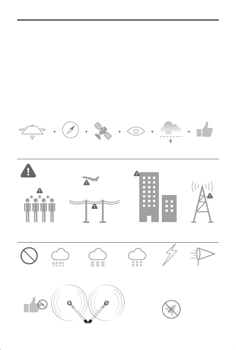
m
Fly in Open Areas Calibrate the
Avoid ying over or near obstacles, crowds, high voltage power lines or bodies of water.
DO NOT y near strong electromagnetic sources such as power lines and base stations as it may affect the onboard
compass.
DO NOT use the aircraft in adverse weather conditions such as rain (precipitation rate exceeding 25 mm in 12 hours), wind
speeds exceeding 8 m/s, fog, snow, and lightning.
Compass
Stay away from the rotating
propellers and motors.
Strong GPS
Signal
Maintain Line
of Sight
Fly Below (50 m)
8m/s
No Fly Zone
Learn more at:
http://www.dji.com/y-safe/
category-mc
© 2016 DJI All Rights Reserved.
7
Page 8
Prole
Introduction
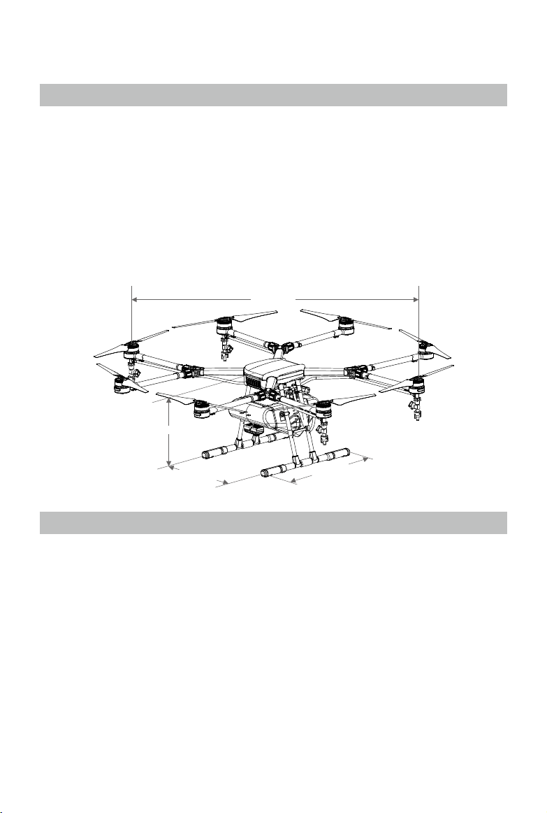
The Agras MG-1 (abbreviated as MG-1) is a battery-powered multirotor aircraft designed for
agricultural applications in variety of environments and terrains, including terraces, elds, forests
and orchards. It is dust-proof, water-proof (IP43 protection rating, IEC standard 60529) and made
of anti-corrosive materials, allowing it to be rinsed clean.
The MG-1 also includes DJI’s industry-leading flight control system and three useful Operation
Modes: Smart, Manual and Manual Plus. A microwave radar underneath the aircraft makes the
MG-1 uniquely versatile across different terrains and the combined Altitude Stabilization System
automatically maintains the aircraft’s height above plants to ensure optimal spraying.
The remote controller features a Spraying Status Panel decorated with intuitive icons and a range of
controls for navigation, mode and spraying. While the MG-1 does all the hard work in the elds, you
keep full control over it in the palm of your hands.
1520 mm
482 mm
511 mm
460 mm
Feature Highlights
The MG-1 provides three useful Operation Modes: Smart, Manual and Manual Plus.
In Smart Operation Mode, the aircraft will travel along a pre-planned route and spray liquid payload.
Users can set the operation gap, ying speed and other parameters. The MG-1 can cover an area of 7-10
acres per hour.
In Manual Operation Mode, users can start and stop spraying manually and also adjust the spray rate.
In Manual Plus Operation Mode, the flying speed is restricted and the aircraft’s heading is locked.
Except for the heading, users can control the movement of the aircraft.
The MG-1 also includes two intelligent memory features: operation resumption and system data
protection. When the operation mode is changed from Smart Operation Mode, operation resumption
records a set point for the aircraft to return to when Smart Operation Mode is reinstated. System data
protection keeps the system data for a period of time even when powered off so users can resume their
missions after replacing the battery.
The spraying system includes a spray tank, sprinklers and other accessories. The four sprinklers placed
on the aircraft’s two sides provide well-distributed spraying and great coverage. The nozzles on the
Agras MG-1 can also be swapped out to meet the needs of different applications.
© 2016 DJI All Rights Reserved.
8
Page 9
AGRAS MG-1 User Manual
The Altitude Stabilization System uses an advanced radar module to keep a constant height above
crops in both Smart Operation Mode and Manual Plus Operation Mode.
Overview
Aircraft
[1]
[2]
[3]
[4]
[5]
[6]
[7]
[16]
[17]
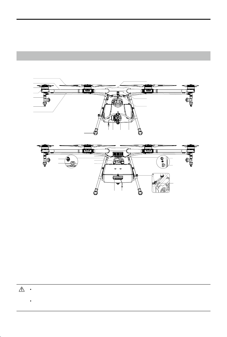
[1] Propellers
[2] Frame Arms
[3] Motors
[4] Orientation Indicators
[5] Sprinklers
[6] Nozzles
[7] Hoses
[8] Landing Gear
[9] Pump Motor Cable
[10] Pump Motor
[8]
[18]
[19]
[20]
[9] [10] [11] [12]
[21] [22]
[11] Delivery Pump
[12] Spray Tank
[13] Aircraft Status Indicator
(Aircraft’s Rear)
[14] Aircraft Body
[15] GPS Module
[16] Motor Port
[17] Flight Controller Data Port
(Micro USB)
[18] Intake Vent (Aircraft’s Front)
[15]
[14]
[13]
[25]
[24]
[23]
[19] Power Ports
[20] Battery Compartment
[21] Radar Module
(Altitude Stabilization)
[22] Radar Cable
[23] Remote Controller Holder
[24] Lightbridge 2 / iOSD Data
Port (Micro USB)
[25] Radar Port
DO NOT obstruct the GPS module located at the center of the aircraft, as this will reduce
the GPS signal strength.
The MG-1 does not come with a battery. Please purchase the DJI approved MG-1 battery
pack (Model: MG-12000).
© 2016 DJI All Rights Reserved.
9
Page 10
AGRAS MG-1 User Manual
Remote Controller
[1]
[2]
[10 ]
[11]
[13 ]
[12 ]
[3]
[4]
[5] [6]
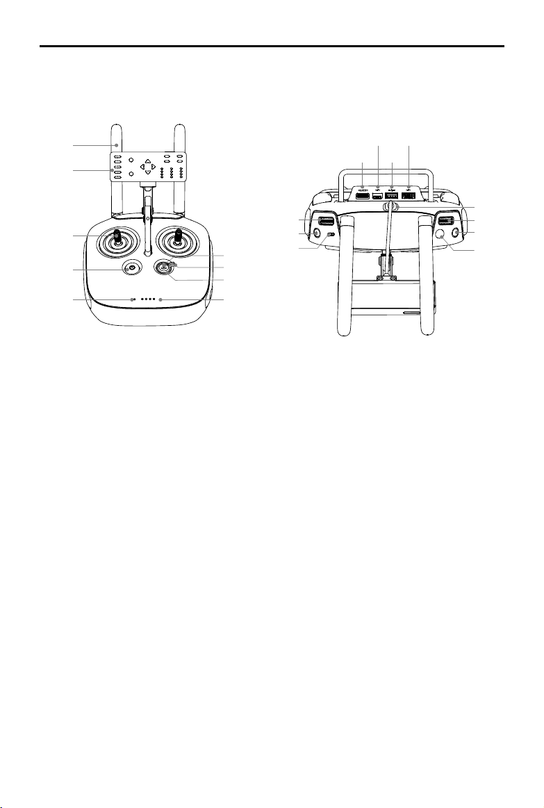
[1] Antennas
Relays the aircraft control signals
[2] Spraying Status Panel
Displays the spraying status.
[3] Control Stick
Controls the aircraft movement. Can be set
to Mode 1 or Mode 2, or to a custom mode.
[4] Power Button
Used to power on/off the remote controller.
[5] Status LED
Indicates whether the remote controller is
linked to the aircraft.
[9]
[8]
[7]
[14 ]
[15 ]
[16 ]
[8] Operation Mode Switch
Used to switch between Smart, Manual and
Manual Plus Operation Mode.
[9] RTH Button
Press and hold this button to initiate Returnto-Home (RTH).
[10] Mini HDMI Port
Reserved.
[11] Micro USB Port
Reserved.
[12] CAN Port
Connects to the Spraying Status Panel.
[20]
[19 ]
[18 ]
[17 ]
[6] Battery Level LEDs
Display the current battery level.
[7] RTH Status LED
Circular LED around the RTH button which
displays the RTH status.
© 2016 DJI All Rights Reserved.
10
[13] USB Port
Connects to your mobile device to
congure the remote controller.
[14] Spray Rate Dial
In Manual Operation Mode, turn the dial to
adjust the spray rate.
Page 11
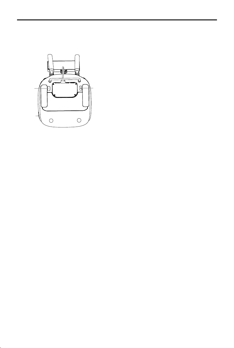
[21]
[23]
AGRAS MG-1 User Manual
[17] Button A
Records Point A of the operation route.
[18] Button B
Records Point B of the operation route.
[19] Flying Speed Dial
In Smart Operation Mode, turn and press
the dial to adjust the ying speed.
[22]
[15] Spray Button
In Manual Operation Mode, press to start
/ stop spraying.
[16] Flight Mode Switch
Used to switch between P-mode
(Positioning), A-mode (Attitude) and
M-mode (Manual).
[20] Panel Cable
Connects to the CAN port.
[21] Back Right Button C2
Press to choose operation route R for
Smart Operation Mode.
In Manual Plus Operation Mode, press to
y the aircraft right for one operation gap.
[22] Power Port
Connects to a power source to charge
the remote controller’s internal battery.
[23] Back Left Button C1
Press to choose operation route L for
Smart Operation Mode.
In Manual Plus Operation Mode, press to
y the aircraft left for one operation gap.
© 2016 DJI All Rights Reserved.
11
Page 12

Installation
Threadlocker is required for installation. Apply threadlocker when mounting landing gear,
spray tank, sprinklers and radar module. Ensure threadlocker is totally dry and solid
before ight.
Ensure that all installation and connection procedures are completed before powering on
the aircraft.
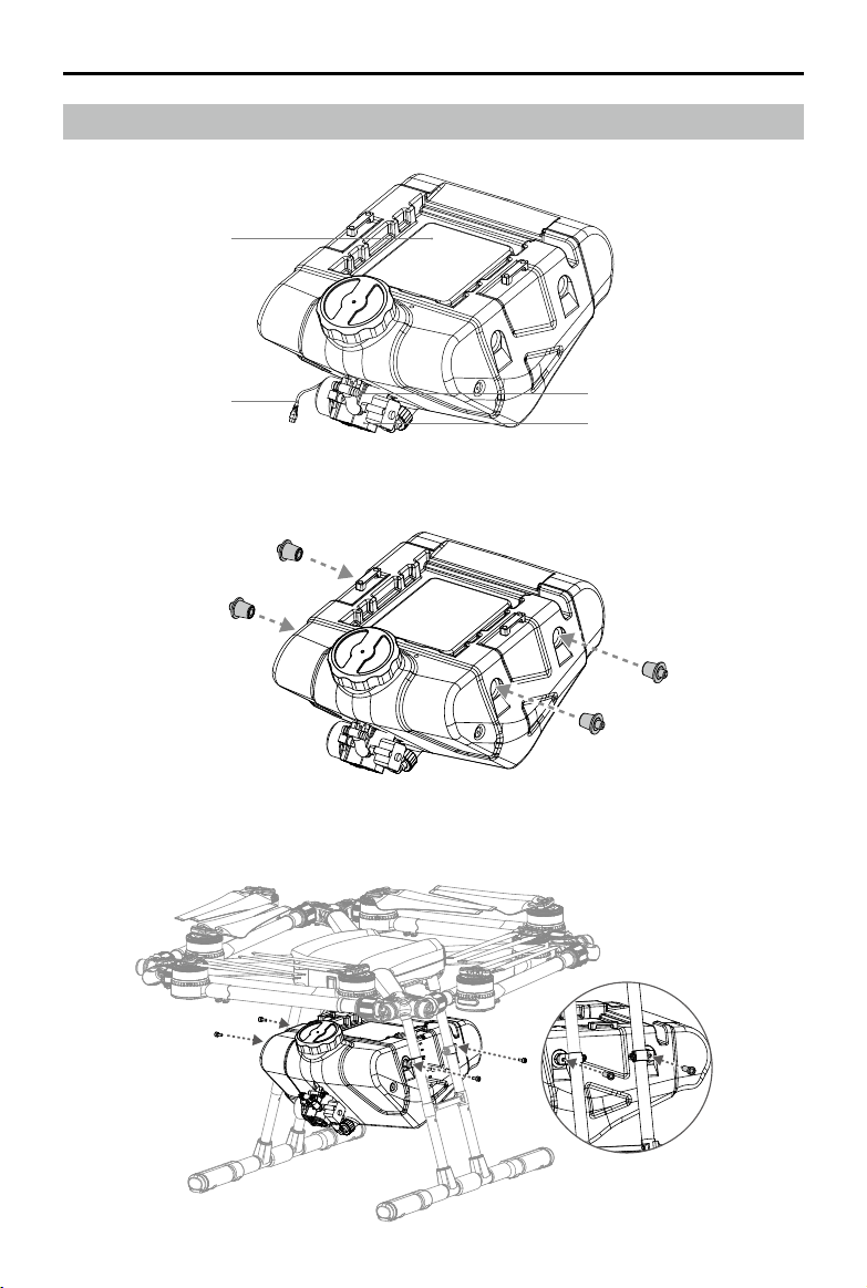
Mounting the Landing Gear
(For the right landing gear leg only)
The structures of the two landing gear legs are different. The one with a compass cable
should be mounted to the right side of the aircraft (when looking from the rear).
1. Identify the landing gear leg containing the compass cable.
2. Take out the cable protector from the landing gear leg and open it. Looking from the rear,
connect the compass cable to the compass port on the right side of the aircraft body. Put the
assembled cable into the cable protector slot and close it. Be careful not to damage the cable.
3. Place the cable protector and cable into the mounting position on the center frame then mount
the right landing gear leg to the mounting position and tighten the M3×10 screws.
Aircraft’s Rear
Compass Cable
Hose Br acket
Cable Protector
Compass Port
Compass Cable
4. Mount the left landing gear leg and tighten the four M3×10 screws.
© 2016 DJI All Rights Reserved.
12
Page 13
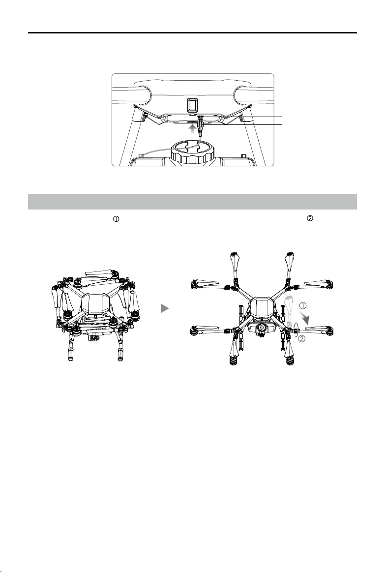
Mounting the Spray Tank
Battery Compartment
AGRAS MG-1 User Manual
Pump Mot or Cable
1. Insert the four spray tank plugs into the sides of the spray tank.
2. Place the spray tank between the landing gear legs with the delivery pump at the rear of the
aircraft. Align the mounting holes and tighten the four M5×18 screws.
Outlet
Deliv ery Pump
© 2016 DJI All Rights Reserved.
13
Page 14
AGRAS MG-1 User Manual
3. Connect the motor cable to the aircraft body. Be sure the plug is correctly orientated.
Motor Port
Pump Motor Cable
Unfolding the Frame Arms
1. Unfold the frame arms and tighten the two arm sleeves at each of the junctions .
M1M2
M3
M4
M5 M6
M8
M7
2. Identify the position and rotational direction of the motors. The top view shows motors M1 to M8
arranged in a counter-clockwise order, with motors M1 and M2 at the front of the aircraft, and
motors M5 and M6 at the rear. Motors M1, M3, M5 and M7 rotate counter-clockwise as indicated
by the “CCW” mark, while motors M2, M4, M6 and M8 rotate clockwise as indicated by the “CW”
mark.
© 2016 DJI All Rights Reserved.
14
Page 15
AGRAS MG-1 User Manual
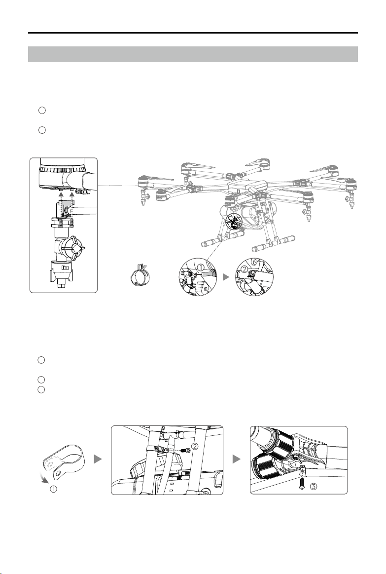
Mounting the Sprinklers
Tools required: A pair of pliers
1. Mount one pair of sprinklers under the left motors (M3 and M4) and the other pair under the right
motors (M7 and M8), and then tighten the M3x6 screws.
2. Connect the sprinklers to the delivery pump.
1
Thread the open ends of the hoses through hose clamps A (use pliers to open up the hose
clamp if necessary). Connect the hoses to both sides of the delivery pump’s T-shape outlet.
2
Press the hose clamps so that they grip the outlet rmly.
Hose Clamp A
3. Fix the hoses to the landing gear and frame arms.
Prepare hose clamps B, M3×6 screws and M3×8 screws (self-tapping) to x the hoses to the
arms and landing gear.
1
Clip hose clamps B around the hose at positions that need to be xed. The hoses should be
xed to the landing gear and at each frame arm junction that leads to a sprinkler.
2
Attach the hose clamp to the bracket on the landing gear leg and tighten the M3×6 screw.
3
Attach the hose clamp to the bottom of the frame arm junction and tighten the M3×8 screw
(self-tapping)
© 2016 DJI All Rights Reserved.
15
Page 16
AGRAS MG-1 User Manual
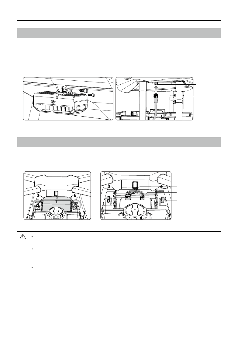
Mounting the Radar Module
1. With the Radar Status Indicator facing outwards, align the mounting holes and tighten the two
M3×8 screws.
2. Connect the radar cable to the radar port on the aircraft body. Be sure to insert the plug in the
correct orientation and tighten its ring to secure.
Radar Port
Radar Cable
Mounting the Battery
Place the battery into the recessed area above the spray tank. Pull the Velcro strap through the
slots and around the battery to secure.
Battery Communication
Port
XT90 Port
Slots
The MG-1 does not come with a battery. Please purchase the DJI approved MG-1 battery
pack (Model: MG-12000).
The voltage on the aircraft can reach 50.4 V. Read the battery’s safety guidelines and
take necessary precautions when handling the battery to ensure your own safety. DJI
assumes no liability for damages(s) or injuries incurred from using the battery improperly.
Ensure that all installation and connection procedures are completed before powering
on the aircraft. To power on, connect the battery to the battery communication port then
the XT90 port. To power off, disconnect the battery from the XT90 port then the battery
communication port.
© 2016 DJI All Rights Reserved.
16
Page 17

Remote Controller
Profile
The aircraft remote control system operates at 2.4 GHz and the maximum transmission distance is 1
km. The remote controller features a number of spraying system control functions to help complete
operations. An internal battery ensures a long battery life (continuously operating for up to four
hours) and ease of use.
Stick Mode: Stick mode can be set to Mode 1 or Mode 2, or to a custom mode. It is set
to Mode 2 by default.
Mode 1: The right stick serves as the throttle.
Mode 2: The left stick serves as the throttle
To prevent transmission interference, do not operate more than three aircrafts in the same
area.
Prepare the Remote Controller
Mounting the Spraying Status Panel
1. Unfold the Spraying Status Panel.
2. Plug the screw lock into the screw hole and tighten.
3. Insert the slotted screw through the metal loop and tighten.
4. Tilt the Spraying Status Panel to the desired position. Adjust the antennas as shown.
5. Connect the panel cable to the CAN port on the back of the remote controller.
© 2016 DJI All Rights Reserved.
17
Page 18

AGRAS MG-1 User Manual
Using the Remote Controller
Turning the Remote Controller On and Off
The remote controller is powered by a 2S rechargeable battery
that has a capacity of 6000 mAh. The battery level is indicated
via the Battery Level LEDs on the front panel. Follow the steps
below to turn on your remote controller:
1. When the remote controller is turned off, press the Power
Button once. The Battery Level LEDs will display the current
battery level. Charge the battery if the battery level is low.
2. Press the Power Button once. Then press again and hold the
Power Button to turn on the remote controller.
3. The remote controller will beep when it is turned on. The
Status LED will rapidly blink green, indicating that the remote
controller is linking to the aircraft. The Status LEDs will glow
solid green when linking is complete.
4. Repeat Step 2 to turn off the remote controller.
Charging the Remote Controller
Charge the remote controller using the included charger. Refer to the gure below for more details.
Power Outlet
Charger
Controlling the Spraying System
Adjust the ying speed, record Point A and B, start or stop spraying, adjust spray speed, choose
the route direction via the Flying Speed Dial, Button A / B, Spray Button, Spray Speed Dial, Button
C1 / C2.
[1]
[2]
© 2016 DJI All Rights Reserved.
18
[5]
[4]
[3]
[6] [7]
Page 19

AGRAS MG-1 User Manual
[1] Spray Rate Dial
In Manual Operation Mode, turn the dial to adjust the spray rate*. Turn the dial to the left to
reduce the spray rate. Turn the dial to the right to increase the spray rate. The Spraying Status
Panel will indicate the current spray rate. Refer to Spraying Status Panel (p. 24) for details.
*
Spray rate may vary according to the nozzle model and viscosity of liquid. For water, when using
four XR11001 nozzles, the minimum rate is 1.2 L/min and the maximum rate is 1.7 L/min.
[2] Spray Button
In Manual Operation Mode, press the button to start or stop spraying.
[3] Button A
Press the button to record Point A of the Smart Operation route.
[4] Button B
Press the button to record Point B after recording Point A.
[5] Flying Speed Dial
In Smart Operation Mode, turn and press the dial to adjust the ying speed. You can set four
speed gears in the MG-1 Assistant. The four speed gears are set to 1, 3, 5, 7 m/s by default,
and the initial ying speed is the speed of the rst gear. Move the dial to the left and press the
dial to change to the previous speed. Move the dial to the right and press the dial to change to
the next speed. The Spraying Status Panel will indicate the current speed gear.
The nal movement of the dial before you press the dial will be used to set the ying
speed.
[6] Back Left Button C2
Press to choose operation route R for Smart Operation Mode.
In Manual Plus Operation Mode, press to y the aircraft right for one operation gap
[7] Back Right Button C1
Press to choose operation route L for Smart Operation Mode.
In Manual Plus Operation Mode, press to y the aircraft left for one operation gap.
In Smart Operation Mode, when the aircraft is hovering at the turning point, press Button C1 and C2
together and then the aircraft will y to the next turning point and hover. Press and hold Button C1
and C2 together for 2 to 4 seconds until there is a beep emitted from the remote controller, and the
aircraft will enter or quit Continuous Smart Operation Mode. Refer to Smart Operation Mode (p. 26)
for more details.
© 2016 DJI All Rights Reserved.
19
Page 20

AGRAS MG-1 User Manual
Controlling the Aircraft
The remote controller is set to Mode 2 by default.
Remote Controller
(Mode 2)
Aircraft
(
Indicates Nose Direction
Remarks
)
Vertical movement of the left stick controls
the aircraft’s elevation. Push up to ascend
and press down to descend. Use the
left stick to take off when the motors are
spinning at idle speed. The aircraft will
hover in place if the stick is in the central
position.
The more the stick is pushed away from the
central position, the faster the aircraft will
change elevation.
Horizontal movement of the left stick
controls the aircraft's heading. Move left to
rotate the aircraft anticlockwise and move
right to rotate the aircraft clockwise. The
aircraft will hover in place if the stick is in
the central position.
The more the stick is pushed away from the
central position, the faster the aircraft will
rotate.
Vertical movement of the right stick controls
the aircraft’s pitch. Push up to y forwards
and press down to fly backwards. The
aircraft will hover in place if the stick is in
the central position.
Move the stick further for a larger pitch
angle and faster ight.
Horizontal movement of the right stick
controls the aircraft’s roll. Move the stick left
to y left and right to y right.
The aircraft will hover in place if the stick is
in the central position.
Move the stick further for a larger roll angle
and faster ight.
The description above is only for the P-mode and A-mode.
© 2016 DJI All Rights Reserved.
20
Page 21

AGRAS MG-1 User Manual
Flight Modes
Toggle the Flight Mode Switch on the remote controller
to one of the three modes.
P
Figure Flight Mode
P
A
M
P-mode (Positioning): The aircraft uses GPS for positioning. In P-mode, when the GPS signal is
strong, users can start the motors.
A-mode (Attitude): GPS is NOT used for positioning and aircraft can only maintain altitude using
the barometer. Aircraft can still record its position and return to the Home Point if a GPS signal is
present.
M-mode (Manual): GPS and attitude stabilization are disabled and you have total control of the
aircraft by yourself. For safety reasons, M-mode is disabled on the remote controller by default. You
can change the ight mode switch “M” value from “Attitude” to “Manual” mode in the PC Assistant,
but this is only recommended for experienced users.
P-mode (Positioning)
A-mode (Attitude)
M-mode (Manual)
M
A
Operation Mode Switch
Toggle the Operation Mode Switch on the remote controller to one of the three modes.
Smart Operation Mode (S) Manual Operation Mode (M) Manual Plus Operation Mode (M+)
1. Smart Operation Mode: When the aircraft is in P-mode and the GPS signal is strong, toggle the
switch to this mode after Points A and B are recorded. The aircraft will y and spray liquid along
the specied route.
2. Manual Operation Mode: In Manual Operation Mode, users can control all the movements of the
aircraft and spray liquid via the Spray Button.
3. Manual Plus Operation Mode: In Manual Plus Operation Mode, the ying speed is restricted and
the aircraft’s heading is locked. Users can control the movement of the aircraft except for the
heading. Press Button C1 or C2 and the aircraft will y one operation width to the left or right.
RTH Button
Press and hold the RTH Button to bring the aircraft back to the last
recorded Home Point. The LED around the RTH Button will blink white
during the RTH procedure. Users can control the aircraft during the
procedure. Regain control manually to cancel the RTH procedure. Refer
to How to Regain Control (p. 33) for details.
© 2016 DJI All Rights Reserved.
21
Page 22

AGRAS MG-1 User Manual
Optimal Transmission Range
Optimal Transmission Range
Strong Weak
The signal transmission between the aircraft and the remote controller performs best when the
aircraft is within the optimal transmission range. Open up the antennas on the remote controller to
optimize transmission range. Ideally, the at surface of the antenna should be facing the aircraft. If
the signal is weak, y the aircraft closer to you.
Remote Controller LED
RTH Status LED
Status LED
The Status LED indicates the connection status between the remote controller and the aircraft. The
RTH Status LED indicates the Return-to-Home status of the aircraft. See the table below for details
on these indicators.
Status LED Sound Remote Controller Status
— Solid Red chime
— Solid Green chime
Blinks Red 1 slow beep repeating Remote controller error.
RTH Status LED Sound Aircraft Status
— Solid White chime Return-to-Home procedure is initiated.
Blinks White 1 beep repeating
Blinks White 2 beeps repeating The aircraft is returning to the Home Point.
© 2016 DJI All Rights Reserved.
22
The remote controller is not connected to
the aircraft.
The remote controller is connected to the
aircraft.
Sending Return-to-Home command to the
aircraft.
Page 23

AGRAS MG-1 User Manual
Remote Controller Calibration
Remote Controller Calibration
Stick Mode
Default stick mode is Mode 2, changing stick modes alters the way the aircraft is controlled.
Remote Controller Settings
Launch the DJI GO App
1. Scan the QR code or visit http://m.dji.net/djigo to download the app.
DJI GO supports iOS 8.0 (or later) or Android 4.1.2 (or later).
2. Connect your mobile device to the remote controller via a USB cable.
3. Go to the Camera View, and tap
window. Tap “Remote Controller Settings” to set the stick mode and link the remote controller.
Stick Mode
Tap “Stick Mode” to enter the stick conguration. It can be set to Mode 1, Mode 2, or to a custom
mode.
Remote Controller Calibration
Stick Mode
Default stick mode is Mode 2, changing stick modes alters the way the aircraft is controlled.
Do not change unless familiar with your new mode.
to enter the remote controller settings
Remote Controller Calibration
Linking Remote Controller
Linking the Remote Controller
The remote controller is linked to your aircraft by default. Linking is only required when a new
remote controller is used for the rst time. Follow these steps to link a new remote controller:
1. Power on the aircraft. Tap “Linking Remote Controller” in the DJI GO app.
2. The remote controller Status LED will blink blue and beep to indicate that the remote controller is
ready to be linked.
Remote Controller Settings
Remote Controller Calibration
Stick Mode
Default stick mode is Mode 2, changing stick modes alters the way the aircraft is controlled.
Do not change unless familiar with your new mode.
Searching for aircraft frequency,
timeout in 54 seconds
Cancel
3. The remote controller will search for aircraft nearby. The remote controller Status LED will glow
Linking Remote Controller
solid green if linking is successful
© 2016 DJI All Rights Reserved.
23
Page 24

AGRAS MG-1 User Manual
Spraying Status Panel
[12]
[11]
[3]
[1]
[2]
[4] [5] [6] [7]
[1] Flight Battery Level LEDs
Displays the current ight battery level. See the table below for details. (The bottom is LED1 and
the top is LED5.)
LED is on. LED is blinking. LED is off.
LED1 LED2 LED3 LED4 LED5 Battery Level
[10]
[9]
[8]
90% 100%
80% 90%
70% 80%
60% 70%
50% 60%
40% 50%
30% 40%
20% 30%
10% 20%
0% 10%
=0%
[2] Point A LED
The LED is on when Point A is recorded.
[3] Point B LED
The LED is on when Point B is recorded.
[4] Orientation LEDs
In Smart Operation Mode, the LEDs indicate the current ying orientation.
[5] Spray Rate LEDs
Displays the current spray rate. More glowing LEDs indicate a larger spray rate. Spray rate may vary
according to nozzle model and viscosity of liquid. For water, when using four XR11001 nozzles, the
minimum rate is 1.2 L/min (the LED at the bottom is blinking) and the maximum rate is 1.7 L/min (all
the four LEDs are on).
[6] Height LEDs
Displays the spraying distance between the aircraft and the crops (or the surface under the aircraft).
© 2016 DJI All Rights Reserved.
24
Page 25

AGRAS MG-1 User Manual
See the table below for details. (The bottom is LED1 and the top is LED4.)
LED is on. LED is blinking. LED is off.
LED1 LED2 LED3 LED4 Spraying Distance
< 2 m
2 - 2.5 m
2.5 - 3 m
3 - 3.5 m
3.5 - 4 m
4 - 4.5 m
4.5 - 5 m
> 5 m
The ight controller is not processing radar data:
1. The radar module is disabled in the MG-1 Assistant.
2. If the radar module is enabled in the MG-1 Assistant, enter
Manual Operation Mode to adjust spraying distance to within
the working range (2 - 3.5 m) and return to Smart Operation
Mode.
Invalid data, adjust the spraying distance to within the
detection range (1.5 - 7 m). Or abnormal radar cable
connection, check the connection.
[7] Flying Speed LEDs
In Smart Operation Mode, the LEDs display the current speed gear. You can set four speed gears in
the A2-AG Assistant. Select the speed gear via the Flying Speed Dial on the remote controller. The
number (1 to 4) of the LED(s) that is/are on indicates the current speed gear (i.e. the rst to the fourth
gear).
[8] Return LED
In Smart Operation Mode, if the operation resumption function is initiated, the Return LED will be on
when the aircraft ies back to the recorded stopping point.
[9] Continuous Smart Operation LED
The LED indicates that the aircraft is in Continuous Smart Operation Mode. In Smart Operation
Mode, when the aircraft is hovering at the turning point, press and hold Buttons C1 and C2
together for 2 to 4 seconds until there is a beep emitted from the remote controller, and the
aircraft will enter Continuous Smart Operation Status. Refer to Smart Operation Mode (p. 26)
for more details.
[10] Spray LED
The LED is on when the aircraft is spraying liquid.
[11] Liquid Level LED
The LED is solid green when there is liquid in the liquid tank. The LED blinks red when there is no
liquid in the liquid tank.
[12] Brightness Setting Button
Press to adjust the LED brightness of the panel. Adjusting to the left reduces the brightness and
adjusting to the right increases the brightness.
© 2016 DJI All Rights Reserved.
25
Page 26

Aircraft
Profile
The MG-1 provides Smart Operation Mode, Manual Operation Mode and Manual Plus Operation
Mode. The Altitude Stabilization System included with the MG-1 keeps a constant height above
crops in Smart Operation Mode and Manual Plus Operation Mode. Functions such as operation
resumption, system data protection, empty tank warning, Return-to-Home (RTH) and low battery
level warning are also available.
When using your MG-1 for the rst time, you will need to activate it in the MG-1 Assistant.
Refer to MG-1 Assistant (p. 34) for details.
Effective use of pesticides relies on pesticide density, spray rate, spray distance, aircraft
speed, wind speed and wind direction. Consider all factors when using pesticides.
Always y at an appropriate height above crops to avoid damage.
Operation Mode
The MG-1 provides Smart Operation Mode, Manual Operation Mode and Manual Plus Operation
Mode. Switch to one of the three modes via the Operation Mode Switch on the remote controller. In
Smart Operation Mode, the aircraft will travel along a pre-planned route and spray liquid payload. In
Manual Operation Mode, users can start and stop spraying manually and also adjust the spray rate.
In Manual Plus Operation Mode, the ying speed is restricted and the aircraft’s heading is locked.
Except for the heading, users can control the movement of the aircraft.
Smart Operation Mode
In Smart Operation Mode, the aircraft will travel along a pre-planned route. Operation resumption,
data protection, and altitude stabilization system are available in this mode. Use the Flying Speed
Dial on the remote controller to adjust ying speed, spray rates will automatically adjust accordingly.
Smart Operation Mode is recommended for large, rectangular spray areas.
Operation Route
The aircraft will travel along pre-designated square zig zag route after the turning points A and B
have been recorded. The altitude difference between the aircraft and vegetation is maintained under
optimal working conditions. The aircraft will spray liquid automatically while ying along the route
and stop spraying liquid while hovering at the turning points. The length of the dotted lines, which
are called Operation Gaps, can be adjusted in the MG-1 Assistant.
© 2016 DJI All Rights Reserved.
26
B
L1
L4 R5
L5
A
L2 R3
L3
L6
Route L Route R Legends
B R1
A
R4
…………
- - - -
Operation Gap
R2
R6
Turning Point
Page 27

AGRAS MG-1 User Manual
Operation Procedure
Maintain line of sight of the aircraft at all times.
Ensure that the Flight Mode Switch is toggled to the “P” position and the GPS signal
is strong (GPS count ≥ 6, refer to Appendix on p. 47 for blinking pattern description).
Otherwise, Smart Operation may be unreliable.
Always inspect operating environments before ying.
Ensure that Flight Mode Switch on the remote controller is toggled to the
“P” position and a strong GPS signal is present. In addition, ensure that the
Operation Mode Switch on the remote controller is toggled to the “M” position.
1. Record Points A and B in Order
Fly the aircraft to the starting point, depicted as Point A (B), hover, and then
press Button A (B) on the remote controller. The Point A (B) LED on the
Spraying Status Panel will become solid green and the Aircraft Status Indicator
will blink red (green) after the starting points have been recorded.
Update Point B by ying the aircraft to a new position and record this position. Note that if
a Point A has been updated, then Point B is also required to be updated accordingly.
It’s recommended to keep the direction of Point A to B parallel to one side of the
rectangular spray area for optimal effect.
2. Select the Route
Press Back Left Button C1 or Back Right Button C2 on the remote controller to select the operating
pattern. Press Back Left Button C1 for Route L and Back Left Button C2 for Route R. The Orientation
LED on the Spraying Status Panel will blink to show that the selection has been made. The default
route pattern is Route R, if no selection has been made.
3. Adjust the Aircraft Altitude
Adjust the aircraft altitude to the desired altitude by using the throttle stick before entering Smart
Operation Mode, and the Altitude Stabilization System will start working automatically and maintain
the spraying distance between the aircraft and the vegetation. Refer to Altitude Stabilization System
(p. 30) for details.
4. Using Smart Operation Mod
Ensure that the Flight Mode Switch on the remote controller is toggled
to the “P” position and a strong GPS signal is present, then toggle the
Operation Mode Switch to the “S” position to enable Smart Operation
Mode. The aircraft will align with the line between Point A and Point
B with its heading pointing toward Point B, and the left and right
Orientation LEDs on the Spraying Status Panel will start blinking.
Aircraft nose will always point from Point A to Point B regardless of the flight direction.
Heading cannot be adjusted.
© 2016 DJI All Rights Reserved.
27
Page 28

AGRAS MG-1 User Manual
5. Starting the Operation
a. Press the Back Left Button C1 and Back Right Button C2 on the remote controller simultaneously
to have the aircraft traverse from Point B to L1 (R1). The aircraft will then hover at Point L1 (R1)
and wait for further commands. The left (right) Orientation LED on the Spraying Status Panel will
light up when ying from Point B to L1 (R1). The four Orientation LEDs on the Spraying Status
Panel will blink when hovering at Point L1 (R1).
b. Repeat ‘a’ and the aircraft will y to the next turning point along Route L (R) and hover.
c. Enable Continuous Smart Operation Mode by pressing and holding the Back Left Button (C1)
and Back Right Button (C2) for 2 to 4 seconds when the aircraft is hovering at any given turning
point. The Continuous Smart Operation Mode LED on the Spraying Status Panel will light up and
the Aircraft Status Indicator will turn solid purple for one second. The aircraft will then y along
Route L (R) continuously.
d. To exit Continuous Smart Operation Mode, press the Back Left Button (C1) and Back Right
Button (C2) and hold for 2 to 4 seconds. The aircraft will y to the next turning point and hover.
You will only be able to press and hold the C1 and C2 buttons for steps 'a' to 'c' when the
aircraft is hovering at a turning point.
If the GPS signal is weak (GPS count < 6) during operation, the aircraft will switch
to Attitude Flight Mode automatically. Exit Smart Operation Mode and control the
aircraft manually. When the MG-1 regains GPS signal, it will y to the next turning point
automatically.
If you press Button A or Button B during operation, data for Point A and B of the current
route will be erased and the aircraft will hover in place.
The Operation Gap is set to 5m by default. Customize it from 3m to 10m in the MG-1
Assistant.
Use the control sticks to control the aircraft to avoid obstacles when it is in operation,
even though the heading of the aircraft cannot be adjusted. The aircraft will resume the
operation route automatically upon releasing the control sticks. Release the control sticks
only after the aircraft is far away from any obstacles, or else the aircraft may still collide
with obstacles when it resumes its operation route.
The aircraft sprays liquid automatically when ying, and does not spray when hovering.
The spray rate cannot be adjusted in Smart Operation Mode and is the same as the
Manual Operation Mode rate. To adjust the spray rate, enter Manual Operation Mode (refer
to Controlling the Spraying System on p. 18 for details) and then return to Smart Operation
Mode after setting a new rate.
Flying speed can be adjusted via the Flying Speed Dial on the remote controller in Smart
Operation Mode. Refer to Controlling the Spraying System (p. 18) for details.
Operation Resumption
The operation resumption function allows you to temporarily pause an operation (e.g. to rell the
spray, change the battery, etc.) and then resume operation. Toggle the Operation Mode Switch
to exit Smart Operation Mode or initialize the Failsafe RTH or Smart RTH procedure, and the
aircraft will record its location as a stopping point if the GPS signal is strong enough (GPS count
≥ 6). Return to Smart Operation Mode and the aircraft will return to the recorded stopping point
automatically and resume operations.
© 2016 DJI All Rights Reserved.
28
Page 29

AGRAS MG-1 User Manual
Ensure that the GPS signal is strong (GPS count ≥ 6) when using the operation resumption
function. Otherwise, the aircraft cannot record and return to the stopping point.
The stopping point will be updated as long as the Operation Mode Switch is toggled from
Smart Operation Mode to any other mode or RTH (Smart RTH or Failsafe RTH) is triggered
Follow the instructions below to use this function:
1. Toggle the Operation Mode Switch to exit Smart Operation Mode or initialize the Failsafe RTH or
Smart RTH procedure. The current location of the aircraft will be recorded as the stopping point.
2. Fly the aircraft to a safe location before resuming the operation. If the radar module is enabled,
adjust the spraying distance between the aircraft and the vegetation to be within the working
range (2 – 3.5 m). Refer to the Altitude Stabilization System (p. 30) for details.
3. Ensure that the aircraft is in P-mode and the GPS signal is strong enough (GPS count ≥ 6).
Toggle the Operation Mode Switch to enter Smart Operation Mode. The aircraft will return to the
recorded stopping point automatically and resume the operation.
System Data Protection
The System Data Protection feature enables the aircraft to retain vital system data (e.g. the positions
of Point A, Point B and the stopping point) for about 1 minute after the aircraft is powered off.
Retaining vital system data allows the aircraft to resume operation after a short, temporary pause.
Follow the instructions below to use this feature:
1. Toggle the Operation Mode Switch to exit Smart Operation Mode. The current location of the
aircraft will be marked as the stopping point.
2. Land the aircraft and stop the motors.
3. System Data Protection is triggered automatically once the aircraft is powered off. The Aircraft
Status Indicator will glow solid green to show that System Data Protection is successfully
triggered.
4. Replace the battery within the 1 minute window.
5. Restart the aircraft and toggle the Operation Mode Switch to enter Manual Operation Mode.
6. Ensure that the aircraft is in P-mode and the GPS signal is strong enough (GPS count ≥ 6). Start the
motors and elevate the aircraft to a safe altitude. Adjust the spraying distance between the aircraft
and the vegetation, so that the value falls with the range of 2 to 3.5 meters. Refer to the Altitude
Stabilization System (p. 30) for more details.
7. Toggle the Operation Mode Switch to enter Smart Operation Mode. The aircraft will y back to
the previously recorded stopping point and resume its operation
The system data can only be retained for 1 minute. DO NOT power off the aircraft for more than
1 minute if you want to resume operation because the system data will be lost.
Manual Operation Mode
Toggle the Operation Mode Switch to enter Manual Operation Mode. You can control all the
movements of the aircraft, spray liquid via the spray button on the remote controller, and adjust the
spray rate via the dial on the remote controller. Refer to Controlling the Spraying System (p. 18) for
more details on adjusting the spray rate. Manual Operation Mode is ideal for when the operating
area is small.
© 2016 DJI All Rights Reserved.
29
Page 30

AGRAS MG-1 User Manual
Manual Plus Operation Mode
Toggle the Operation Mode Switch to enter Manual Plus Operation Mode. The maximum flying
speed is 8 m/s and the aircraft’s heading is locked in Manual Plus Operation Mode. Press the Back
Left Button (C1) or the Back Right Button (C2) on the remote controller to steer the aircraft to y to
the left or right. Spraying will not be interrupted while the aircraft is shifting to the left or right, and
will only stop when the aircraft is hovering. Manual Plus Operation is ideal for irregularly shaped
operating areas.
1. Elevate the aircraft to a desired altitude before entering Manual Plus Operation Mode. The
Altitude Stabilization System starts working automatically by maintaining the spraying distance
between the aircraft and the vegetation below. Refer to Altitude Stabilization System (p. 30) for
details.
2. Ensure that the aircraft is in P-mode and ensure that GPS signal is strong (GPS count ≥ 6). Then
toggle the Operation Mode Switch to the “M+” position to activate Manual Plus Operation Mode.
Note that the Operation Gap value is identical to the one that has been set in Smart
Operation Mode.
The spray rate is xed in Manual Plus Operation Mode. You can adjust the spray rate in
Manual Operation Mode (refer to Controlling the Spraying System on p. 18 for details) and
then return to Smart Operation Mode after setting a new rate.
Altitude Stabilization System
Profile
To ensure that the spray is evenly dispensed, the aircraft uses the radar module on the Altitude
Stabilization System to maintain the same distance above the crops at all times. The radar module is
enabled by default, and can be disabled in MG-1 Assistant. If it is enabled, the aircraft will y above
the crops at a constant spraying distance in Smart Operation Mode and Manual Plus Operation
Mode. The system can also measure the spraying distance above the crops or other surfaces, but
the aircraft will not be able to y at a constant spraying distance when performing this function.
How to Use
1. Ensure that the Operation Mode Switch is toggled to the Manual Operation Mode. Fly the aircraft
above the vegetation and adjust the spraying distance between the aircraft and the vegetation. DO
NOT operate the aircraft above vegetation beyond the detection range (1.5 - 7 m) while adjusting
aircraft altitude, otherwise the Spraying Status Panel will not be able to display the current spraying
distance.
2. Conrm the desired spraying distance by observing the Height LEDs on the Spraying Status
Panel. Ideal spraying distance should fall within the working range (2 - 3.5 m) for altitude
stabilization. DO NOT operate the aircraft beyond this range, otherwise the system will become
unstable.
© 2016 DJI All Rights Reserved.
30
Page 31

AGRAS MG-1 User Manual
3. Toggle the Operation Mode Switch to enter Smart Operation Mode or Manual Plus Operation
Mode. If operating environment is ideal, the aircraft will y above the vegetation at the pre-set
height.
The Altitude Stabilization System will only maintain a xed distance from vegetation within
its working range (2-3.5 m).
The aircraft’s pitch and roll angles must not exceed 20°.
Observe the aircraft’s distance from the vegetation at all times.
Operate with extra caution in any of the following situations:
a. There are large height differences (> 1m) in vegetation (i.e. nearby ditches or ponds,
above sparse trees or shrubs, terraced elds).
b. Flying at high speeds (> 5m/s).
c. Flying over surfaces that can absorb sound waves (e.g. dense vegetation comprised
of small leaves such as well-maintained grass lawns).
d. Flying over inclined surfaces (depending on aircraft speed). Recommended maximum
inclination at different speeds: 15° at 1 m/s, 6° at 3 m/s and 3° at 5 m/s.
Obey local radio transmission laws and regulations.
Radar Status Indicator
Radar Status Indicator
The Radar Status Indicator shows the current status of the Altitude Stabilization System. See the
table below:
Blinking Patter Description
— Solid Green Warming up.
…… Blinking Green Working.
Off Disconnected.
Empty Tank Warning
Profile
When the spray tank is empty, the Liquid Level LED on the Spraying Status Panel will blink red
and the aircraft will move depending on the operation mode - ascend 3 meters and hover (Smart
Operation Mode) or hover in place (Manual Operation Mode or Manual Plus Operation Mode).
How to Use
1. Press the Spray Button on the remote controller to turn off the sprinklers when the empty tank
warning is triggered in Manual Operation Mode. Failure to do so may cause the idling of the
pump of the motor and subsequently damage the parts. The sprinklers will automatically turn off
in Smart Operation Mode or Manual Plus Operation Mode.
© 2016 DJI All Rights Reserved.
31
Page 32

AGRAS MG-1 User Manual
2. Ensure the aircraft is in Manual Operation Mode, and then land the aircraft and stop the motors.
Rell the liquid tank and tighten the lid.
3. Press the Spray Button on the remote controller to discharge the remaining air in the pump until
the Liquid Level LED on the Spraying Status Panel glows solid green. Press the Spray Button
again to stop discharging.
4. Ensure the aircraft is in Manual Operation Mode, and then take off.
5. Elevate the aircraft to a desired altitude in Smart Operation Mode or Manual Plus Operation
Mode. Adjust the spraying distance between the aircraft and the vegetation to be within the
working range (2 - 3.5 m). Refer to the Altitude Stabilization System (p. 30) for details. Then
toggle the Operation Mode Switch.
Return-to-Home (RTH)
RTH: The Return-to-Home (RTH) function brings the aircraft back to the last recorded Home
Point.
Home Point: If the GPS signal is strong enough (GPS count ≥ 6) after powering on for 30
seconds, then the launching location of the aircraft will be recorded as the Home Point.
When using System Data Protection, the Home Point will not be updated if you restart the
aircraft after changing the battery.
There are two events that will trigger RTH procedure: Smart RTH and Failsafe RTH.
Smart RTH
Use the RTH button on the remote controller (see RTH Button on p. 21 for more details) when GPS
is available to enable Smart RTH. Press and hold the RTH button to enable Smart RTH. The same
RTH procedure is applied to both Smart RTH and Failsafe RTH. With Smart RTH, you may control
the aircraft’s orientation to avoid collisions when it is returning to the Home Point. To exit Smart RTH,
regain control manually. Refer to How to Regain Control (p. 33) for more details.
It is not possible to start the RTH procedure by pressing the RTH button when the Flight
Mode is toggled to the “M” position.
Failsafe RTH
The Failsafe RTH must be enabled in the MG-1 Assistant. If Failsafe RTH is not enabled,
the aircraft will hover in place when the remote controller signal is lost.
Failsafe RTH is activated automatically if the remote controller signal is lost for more than 3 seconds
provided that the Home Point has been successfully recorded and the compass is working normally. The
operator can interrupt the Return-to-Home procedure and regain control over the aircraft if the remote
controller signal is recovered. Refer to How to Regain Control (p. 33) for details.
© 2016 DJI All Rights Reserved.
32
Page 33

RTH Illustrator
1 Record Home Point (HP)
2 Conrm Home Point
<8m
AGRAS MG-1 User Manual
3 Remote Controller Signal Lost
GPS≥7
Blinking Purple
4 Signal Lost Lasts 3secs
Blinking Blue
Blinking Purple 5 Times
5 Go Home (15m can be set)
Height over HP>15m
Elevate to 15m
15m
Blinking Blue
Height over HP<=15m
Blinking Blue
6 Landing after Hovering 15secs
Blinking Blue
When the GPS count is less than 6 or GPS is not working, the aircraft can only stabilize
the attitude without returning to the Home Point.
Start RTH by pressing and holding the RTH button in emergency situations. DO NOT
power off the remote controller to start RTH.
Make sure there are no obstacles during RTH procedure and you are familiar with how to
regain control of the aircraft.
How to Regain Control
The table below shows ways to regain control during the Failsafe RTH procedure. To regain control
during the Smart RTH procedure, refer to the “Positioning” and “Attitude” Flight Mode sections in
the table below.
Flight Mode Switch
Flight Mode Positioning Attitude Manual
Regain control as
soon as the signal
recovers.
Regain Control
Toggle the Flight Mode Switch once to regain
control if the signal recovers.
Low Battery Level Warnings
There are two low battery level warnings:
1. Low battery level warning: the Aircraft Status Indicator blinks yellow. Fly the aircraft back and
land it as soon as possible, then stop the motors and replace the batteries.
2. Critically low battery level warning: the Aircraft Status Indicator blinks red. The aircraft will begin
to descend and land automatically. You can change the settings in MG-1 Assistant so that the
aircraft does not automatically descend and land when the Aircraft Status Indicator LED blinks
red.
The threshold of the two low battery levels can be set in the MG-1 Assistant.
© 2016 DJI All Rights Reserved.
33
Page 34

MG-1 Assistant
When using your MG-1 for the rst time, you will need to activate it in the MG-1 Assistant. Congure
settings of the remote controller, gain values, RTH, Smart Operation Mode and more in the MG-1
Assistant after activation.
Installation and Launching
1. Download the DJI Driver and the MG-1 Assistant installation le from the MG-1 download page.
http://www.dji.com/product/mg-1/info#downloads
2. Complete the installations for the DJI Driver and the MG-1 Assistant software.
3. Launch the MG-1 Assistant software.
Using the MG-1 Assistant
Connect the ight controller data port of the aircraft to your computer with a Micro USB cable. Then
power on the aircraft.
Be sure to remove the propellers before using the MG-1 Assistant.
View Page
Check all basic settings on this page. Click the blue hyperlinks for detail settings.
Basic Page
Be sure to use the default settings for the “Aircraft” and “Mounting” parts.
RC
Flight Mode Switch
Power on the remote controller and toggle the Flight Mode Switch to the M Flight Mode. Then
set as Attitude or Manual mode in the MG-1 Assistant. Manual mode is only recommended for
experienced users.
© 2016 DJI All Rights Reserved.
34
Page 35

AGRAS MG-1 User Manual
Gain
Basic and attitude gain value settings. It is recommended to use the default settings.
Advanced Page
F/S
Failsafe Methods
If you select “Hover”, the aircraft will hover in place when RC signal is lost.
If you select “Alt Go-Home” and input a value (max. 50 m), the aircraft will y back automatically at
the input altitude when RC signal lost.
Battery Level
Turn ON / OFF the low battery level warnings or set the threshold of the two low battery levels and
the types of warnings on this page.
Limits
Turn ON / OFF ight limits on this page.
Agriculture
Operation Gap
Set the Operation Gap from 3 to 10 m. It is set to 5 m by default.
Flying Speed
Set four speed gears for Smart Operation Mode from 1 to 8 m/s. The four speed gears are set to 1, 3,
5, 7 m/s by default.
Enable Radar Module
The module is enabled by default. Uncheck the checkbox if you want to disable the module, so that
the aircraft will not detect the height above the crops.
Tools Page
Cong
Export or import the parameters, restore the default settings and reset the BTU module.
© 2016 DJI All Rights Reserved.
35
Page 36

AGRAS MG-1 User Manual
Sensors
Read gyroscope, acceleration and compass sensor values.
IMU Calibration
There is no need to calibrate the IMU in general. Calibration is required when:
1. Gyroscope Mod value exceeds 1.5.
2. Acceleration Mod value below 0.98 or exceeds 1.02.
Calibration Instructions:
1. Power on the system and wait until the system enters “Ready” status.
2. Click “Calibration” and follow the steps in the software.
Device Info & Connection
Check the current rmware version of the aircraft and ensure the installed rmware is up-to-date. If
not, login with your DJI account and click the hyperlink to upgrade the rmware.
After rmware upgrades, disconnect the Micro USB cable and power off the aircraft. Wait
for the data protection module to fully discharge (Aircraft Status Indicator goes off) before
powering the aircraft back on.
Upgrade the remote controller firmware via the DJI GO app. Refer to Upgrading the
Firmware (p. 48) for details.
Register Page
Activate the aircraft, change user account or view the software information on this page.
Activation Code
Login with your DJI account, enter your activation code and click “Enter” to activate your aircraft.
© 2016 DJI All Rights Reserved.
36
Page 37

DJI Assistant 2
Upgrade the Lightbridge 2 Air System rmware, export the ight data stored on the iOSD in the DJI
Assistant 2.
Installation and Launching
1. Download the DJI Assistant 2 installation le from the MG-1 download page.
http://www.dji.com/product/mg-1/info#downloads
2. Complete the installation for the DJI Assistant 2 software.
3. Launch the DJI Assistant 2 software.
Using the DJI Assistant 2
Connect the Lightbridge 2 / iOSD Data Port of the aircraft to your computer with a Micro USB cable.
Then power on the aircraft.
Be sure to remove the propellers before using the MG-1 Assistant.
Upgrading the Lightbridge 2 Air System Firmware
1. Choose “Lightbridge 2” from the list of connected devices, then sign in with your DJI account.
2. Choose the desired rmware version from the rmware list and click “Upgrade”.
3. After reading the popup notice, click “Start Upgrade”. The text “Upgrade Successful!” will be
displayed when the upgrade is complete. If the upgrade fails, try again or contact DJI Support.
Both the Lightbridge 2 Air System and the remote controller rmware must be up-to-date,
or else they will not link.
Upgrade the remote controller firmware via the DJI GO app. Refer to Upgrading the
Firmware (p. 48) for details.
Exporting Flight Data
1. Sign in with your DJI account, and then choose “iOSD” from the list of connected devices.
2. The iOSD will be connected to the computer as a device with removable storage. Export the data
required from the device named “DJI-IOSDLOG” in the devices list on your computer.
© 2016 DJI All Rights Reserved.
37
Page 38

Flight
Operation Environment
1. DO NOT use the aircraft in adverse weather conditions such as heavy rain (precipitation rate
exceeding 25 mm or 0.98 inches in 12 hours), high winds exceeding 17 mph (28 kph), fog,
snow, lightning, tornadoes or hurricanes.
2. Only fly in open areas. Tall buildings and steel structures may affect the accuracy of the
compass and the GPS signal.
3. Maintain line of sight of the aircraft at all times, and avoid ying near obstacles, crowds, animals,
trees and bodies of water.
4. Avoid ying in areas with high levels of electromagnetism, including mobile phone base stations
and radio transmission towers.
5. Ensure that there is a strong GPS signal in the Smart or Manual Plus Operation Mode.
6. DO NOT operate any parts of the aircraft indoors.
7. The MG-1 cannot operate in P-mode within the Earth’s polar regions.
Flight Limits and No Fly Zones
Unmanned aerial vehicle (UAV) operators should abide by the regulations from self-regulatory
organizations such as the ICAO (International Civil Aviation Organization), the FAA and their local
aviation authorities. For safety reasons, ight limits are enabled by default to help users use this
product safely and legally.
When operating in P-mode, the height limit, distance limit and No Fly Zones work together to monitor
ight. In Attitude Flight Mode, only the height limit prevents the aircraft from going above 50 meters.
Maximum Height and Radius Limits
Users can change the maximum height and radius limits in the MG-1 Assistant. Once complete,
your MG-1 will y in a restricted cylinder that is determined by these settings. The tables below
show the details of these limits.
Max Height
Max Radius
Home Point
Height of aircraft when powered on
GPS Signal is Strong
Flight Limits
Max Height Flight altitude must be below the preset height.
Max Radius Flight distance must be within the max radius.
© 2016 DJI All Rights Reserved.
38
Page 39

AGRAS MG-1 User Manual
GPS Signal is Weak
Flight Limits
Max Height Flight altitude must be below the preset height.
Max Radius No limits.
If you y out of bounds, you can still control the MG-1, but cannot y it further.
If the MG-1 loses GPS signal and flies out of the max radius but regains GPS signal
afterwards, it will y back within range automatically.
No Fly Zones
All restricted areas are listed on the DJI official website at http://www.dji.com/fly-safe/category-
mc. Restricted areas are divided into category A and category B. Category A areas cover major
international airport such as LAX and Heathrow, while category B areas includes smaller airports.c
Category A Safety Zone (requires GPS)
• The category A “safety zone” is comprised of a small “no-y zone” and a range of “restricted-
altitude zones”. Flight is prevented in the “no-y zone” but can continue with height restrictions in
the restricted-altitude zone.
• 1.5 miles (2.4 km) around a designated safety zone is a no-fly zone, inside which takeoff is
prevented.
• 1.5 miles (2.4 km) to 5 miles (8 km) around restricted areas are altitude restricted, with maximum
altitude going from 35 feet (10.5 m) at 1.5 miles (2.4 km) to 400 feet (120 m) at 5 miles (8 km).
• A “warning zone” has been set around the safety zone.
400 feet
320 feet
3.5 mile
5 mile
Category A Safety Zone
1.5 mile
Category A
© 2016 DJI All Rights Reserved.
39
Page 40

AGRAS MG-1 User Manual
Category A Safety Zone
1.5 mile
5 mile
Category B Safety Zone (requires GPS)
Category B “safety zone” is comprised of a “no-y zone” and a “warning zone”.
0.6 miles (1 km) around the safety zone is a designated “no-y zone”.
A “warning zone” has been set around the safety zone.
Category B Safety Zone
0.6mile
0.6mile
GPS Signal is Strong
Zone Restriction Aircraft Status Indicator
No-y Zone
Motors will not start.
If the aircraft loses GPS signal and enters
the restricted area but regains GPS signal
afterwards, the aircraft will enter Semi-
Blink red quickly and
continue for 3 seconds
before normal blinks.
Automatic Descent and land itself.
Restricted-altitude
Flight Zone
Warning Zone
If the aircraft loses GPS signal and enters
the restricted area but regains GPS signal
afterwards, it will descend to a safe altitude
and hover 15 feet below the safe altitude.
No ight restrictions.
Blink yellow quickly and
continue for 3 seconds
before normal blinks.
Free Zone
No ight restrictions. None.
Semi-Automatic Descent:All stick commands are available except the throttle stick command
during the descent and landing process. Motors will stop automatically after landing. Users
must toggle the Flight Mode Switch to regain control. This is the same as regaining control
during RTH. Refer to How to Regain Control (p. 33).
© 2016 DJI All Rights Reserved.
40
Page 41

AGRAS MG-1 User Manual
When ying in No-y zone, the Aircraft Status Indicator will ash red rapidly and continue
for 3 seconds, then switch to indicate the current ying status and continue for 5 seconds,
at which point it will switch back to blinking red rapidly.
When ying in restricted-altitude ight zone and warning zone, the Aircraft Status Indicator
will ash yellow rapidly and continue for 3 seconds, then switch to indicate the current
ying status and continue for 5 seconds, at which point it will switch back to blinking red
rapidly.
For safety reasons, please do NOT y close to airports, highways, railway stations, railway
lines, city centers or other busy areas. Try to ensure the aircraft is visible at all times.
Conditions of Flight Limits
In different working modes and flight modes, flight limits will differ according to number
of GPS satellites found. The following table demonstrates all the cases (√: available; ×:
unavailable).
All ights are restricted by height, distance and special areas simultaneously. The Failsafe is not
restricted to ight limits.
Flight Mode
GPS
Attitude
Manual
Flight Limits can be disabled in the Assistant.
Users cannot take off the aircraft in some Special Areas even the Flight Limits is disabled in
the Assistant.
Number of GPS
Found
≥6 √ √ √
<6 × √ ×
≥6 √ √ ×
<6 × √ ×
≥6 × × ×
<6 × × ×
Limits of Special
Area
Max Height Max Radius
Pre-Flight Checklist
1. The remote controller, aircraft battery are fully charged.
2. The pesticides required are adequate.
3. The position of aircraft battery is secured.
4. All parts are mounted securely.
5. All cables are connected correctly and rmly.
6. Propellers are unfolded and mounted onto the motors securely; frame arms are unfolded and
arm sleeves are rmly tightened.
7. Spraying system is without any blockage.
8. Test the sprinklers. Bubbles in the hoses may lead to operation problems. Loosen the valve on
the side of the sprinkler and start the pump to discharge the bubbles. Then tighten the valve and
the sprinkler will work properly.
© 2016 DJI All Rights Reserved.
41
Page 42

AGRAS MG-1 User Manual
Calibrating the Compass
The compass is built in the landing gear. Be sure to calibrate the compass before your rst ight,
or else the aircraft cannot work properly. The compass is a very sensitive instrument that requires
regular calibration to ensure optimal flight performance. Abnormal compass data due to a lack
of calibration can lead to poor ight performance or even failure. Regular calibration enables the
compass to keep optimal performance.
DO NOT calibrate your compass where there is a chance of strong magnetic interference,
such as magnetite quarries, parking structures, and underground steel reinforcements.
DO NOT carry ferromagnetic objects such as cellular phones with you during calibration.
DO NOT calibrate besides massive metal objects.
DO NOT calibrate in an indoor space.
Calibration Procedures
Choose an open space to carry out the following procedures. It is recommended to calibrate the
compass with an empty tank.
1. Flip the Flight Mode Switch back-and-forth at least 6 times, until the Aircraft Status Indicator
becomes solid blue.
2. Hold the aircraft upright and rotate it 360 degrees along the central axis, until the Aircraft Status
Indicator changes from solid blue to solid green.
3. Hold the aircraft with its nose facing up and rotate 360 degrees along the central axis.
P- mode M- mode
4. The Aircraft Status Indicator shows the current flight mode when calibration is complete. If
the Aircraft Status Indicator becomes blinking red, repeat the steps above to recalibrate the
compass.
When to Recalibrate
1. The compass data is abnormal, and the Aircraft Status Indicator is blinking red and yellow
alternatively.
2. Flying in a new location, or a location that is different from your last ight.
3. The mechanical structure of the MG-1 is changed.
4. Severe drifting occurs in ight, i.e. the MG-1 has difculty ying in a straight line.
© 2016 DJI All Rights Reserved.
42
Page 43

AGRAS MG-1 User Manual
Starting and Stopping the Motors
Starting the Motors
The Combination Stick Command (CSC) listed below is used to start/stop the motors. Ensure you
perform the CSC in one continuous motion. The motors will begin to speed at an idle speed. Take
off immediately after the motors are spinning, or else the aircraft may lose balance, drift or even
takeoff by itself and injure nearby people.
CSC 1 CSC 2 CSC 3 CSC 4
Stopping the Motors
There are two methods to stop the motors.
1. When the aircraft has landed, push the throttle stick down, then perform the CSC command to
stop the motors. Release both sticks once the motors have stopped.
Throttle Stick
2. When the aircraft has landed, push the throttle down and hold. The motors will stop after 3
seconds. (In M-mode, when “M” is set as Manual mode in the MG-1 Assistant, use method 1 to
stop the motors.)
Throttle Stick
Flight Test
1. Place the aircraft near the operation area with the Aircraft Status Indicator facing you.
2. Power on the remote controller. Connect the battery to the communication port and then the
XT90 port.
3. Toggle the Operation Mode Switch to Manual Operation Mode.
4. Toggle the Flight Mode Switch to P-mode. Wait until there is no red blinking from the Aircraft
Status Indicator, which means the GPS signal is strong. Then perform CSC command to start the
motors.
5. Push the throttle stick up to take off.
6. Select the desired Operation Mode and spray liquid.
7. To land, ensure the Operation Mode Switch is toggled to Manual Operation Mode and hover over
a level surface and gently pull down on the throttle stick to descend slowly.
© 2016 DJI All Rights Reserved.
43
Page 44

AGRAS MG-1 User Manual
8. After landing, perform the CSC command to stop the motors.
9. Disconnect the battery from the XT90 port and then the communication port. Then power off the
remote controller.
When the Aircraft Status Indicator blinks blue during flight, the aircraft has entered
Failsafe mode.
The low battery level warning is triggered when the Aircraft Status Indicator blinks yellow.
Fly the aircraft back and land it as soon as possible, then stop the motors and replace the
battery.
The critically low battery level warning is triggered when the Aircraft Status Indicator
blinks red. The aircraft will begin to descend and land automatically. You can change the
settings in MG-1 Assistant so that the aircraft does not automatically descend and land
when the Aircraft Status Indicator LED blinks red.
© 2016 DJI All Rights Reserved.
44
Page 45

Appendix
Specifications
Airframe
Diagonal Wheelbase 1520 mm
Frame Arm Length 625 mm
Dimensions
Propulsion System
Motors
Stator Size 60×10 mm
KV 130 rpm/V
Max Thrust 5.1 kg/rotor
Max Power 770 W
Weight (With cooling fan) 280 g
ESCs
Max Allowable Current (Continuous) 25 A
Operating Voltage 50.4 V(12S LiPo)
Signal Frequency 30 - 450 Hz
Drive PWM Frequency 12 kHz
Foldable Propeller
Material High-performance engineered plastics
Diameter × Pitch 21×7 inch
Weight 58 g
Spraying System
Liquid Tank
Volume 10 L
Standard Operating Payload 10 kg
Max Battery Size 151 mm×195 mm×70 mm
Sprinklers
Model XR11001
Quantity 4
Max Spray Rate 0.43 L/min (Single nozzle, using water)
Spray Width 4 - 6 m (4 nozzles, 1.5 – 3 m above the crops)
Droplet Size
Altitude Stabilization System
Detection Range
Working Range 2 - 3.5 m
Detection Accuracy < 10 cm
1471×1471×482 mm
(Frame arms unfolded, propellers removed)
780×780×482 mm (Frame arms folded)
250 µm (Depending on operating
130
environment and spraying speed)
1.5 - 7 m (Varies when ying above different kinds
of vegetation)
© 2016 DJI All Rights Reserved.
45
Page 46

AGRAS MG-1 User Manual
Flight Parameters
Total Weight (Excluding battery) 8.8 kg
Standard Takeoff Weight 22.5 kg
Max Takeoff Weight 24.5 kg (At sea level)
Max Thrust-Weight Ratio 1.81 (Takeoff weight of 22.5 kg)
Battery DJI approved battery pack (Model: MG-12000)
Max Power Consumption 6400 W
Hovering Power Consumption 3250 W (Takeoff weight of 22.5 kg)
Hovering Time*
Max Operating Speed 8 m/s
Max Flying Speed 22 m/s
Max Service Ceiling Above Sea Level 2000 m
Operating Temperature 0° to 40° C
*At sea level and in wind speeds under 3 m/s
24 min (Takeoff weight of 12.5 kg)
10 min (Takeoff weight of 22.5 kg)
Remote Controller
Model GL658C, GL690B (Japan only)
Operating Frequency
Max Transmission Range 1 km (Unobstructed and free of interference)
EIRP
Built-in Battery 6000 mAh, 2S LiPo
Output Power 9 W
Operating Temperature -10° to 40° C
Storage Temperature
Storage Temperature 0° to 40° C
920.6 MHz to 928 MHz (Japan)
5.725 GHz to 5.825 GHz
2.400 GHz to 2.483 GHz
10 dBm @ 900M
13 dBm @ 5.8G
20 dBm @ 2.4G
Less than 3 months: -20° to 45° C
More than 3 months: 22° to 28° C
Remote Controller Charger
Model A14-057N1A
Voltage 17.4 V
Rated Power 57 W
© 2016 DJI All Rights Reserved.
46
Page 47

AGRAS MG-1 User Manual
Aircraft Status Indicator Description
Blinking Patterns Description
Blinking Purple once P-mode
×2 Blinking Purple twice P-mode, control stick not in mid-point
Blinking Yellow once A-mode
×2 Blinking Yellow twice A-mode, sticks not in mid-point
No Red indicator GPS signal is Best, GPS count > 6
Blinking Red once GPS signal is Good, GPS count = 6
×2 Blinking Red twice GPS signal is Bad, GPS count = 5
×3 Blinking Red three times
×3 Blinking White three times
×4 Blinking Green four times
×4 Blinking Red four times
Blinking Red
(when powering on)
Blinking Yellow and
Green alternately
Blinking Red several
times rapidly
Blinking Green several times
rapidly
×5 Blinking Blue ve times
×5 Blinking Purple ve times Distance from the Home Point within 8 m
Solid Purple for one second Enters Continuous Smart Operation Mode
Blinking Yellow Low battery level
Blinking Red (when ying) Critically low battery level
Blinking Blue Failsafe RTH
Solid Blue Flight controller Activation Code not authorized
Solid Red PMU abnormal or battery not veried
Solid Green System Data Protection function working
GPS signal is Worst, GPS count < 5, motors cannot be
started.
Attitude status bad. Hover or land the aircraft and wait
for the white indicator to go off.
IMU data lost. Restart the aircraft, if not work, contact
DJI Support.
System error. Restart the aircraft, if not work, contact
DJI Support.
Compass data not ready, or compass abnormal.
Check connection.
Abnormal compass data, compass calibration
required.
Point A recorded
Point B recorded
The aircraft flies to the next turning point in Smart
Mode
© 2016 DJI All Rights Reserved.
47
Page 48

AGRAS MG-1 User Manual
Upgrading the Firmware
Aircraft Firmware
Connect the flight controller data port of the aircraft to the MG-1 Assistant on your computer to
upgrade the aircraft rmware. Refer to the Tools Page under Using the MG-1 Assistant (p. 34) for
details.
Lightbridge 2 Air System Firmware
Connect the Lightbridge 2 / iOSD data port of the aircraft to the MG-1 Assistant on your computer to
upgrade the Lightbridge 2 Air System rmware. Refer to DJI Assistant 2 (p. 37) for details.
Remote Controller Firmware
Power on the remote controller, connect the mobile device to the remote controller, and then launch
the DJI GO app to upgrade the remote controller rmware.
1. Go to the DJI GO app > Camera View > System Status bar > Overall Status. Tap Download
Firmware to download and upgrade the rmware.
2. The Status LED will turn solid green when the upgrade is successful. The LED will turn solid red
if the upgrade fails. Restart the remote controller and try again.
The rmware upgrade process takes around 10 minutes. We recommend nding a
comfortable environment to carry out the upgrade.
Both the Lightbridge 2 Air System and the remote controller rmware must be up-to-date,
or else they will not link.
Check in the DJI GO app that you have the latest rmware installed before every ight.
The rmware update requires an internet connection. Connect your mobile device to a
Wi-Fi network whenever possible.
Wait for the progress bar to reach 100% to ensure the rmware upgrade is complete.
The remote controller status indicator glows solid blue during the upgrade.
Do not power off the remote controller during the upgrade.
DO NOT perform the rmware upgrade while the aircraft is ying in the air. Only carry out
the rmware upgrade when the aircraft is on the ground.
The remote controller may become unlinked from the aircraft after the rmware upgrade.
Relink the remote controller and aircraft if necessary.
© 2016 DJI All Rights Reserved.
48
Page 49

AGRAS MG-1 User Manual
DJI GO App
Upgrade and congure the remote controller and view the ying status in the DJI GO app.
Enter Camera View on the Equipment page.
[1] [2] [3] [4] [5] [6] [7] [8]
SAFE TO FLY (GPS)
H: D:
39M 210M
V.S
H.S
M/S
4.22.3
[9]
[1] Back
: Tap this icon to return to the main menu.
232M
M/S
P-GPS
12
48.6V
[2] System Status
: Indicates the current aircraft system status and GPS signal strength.
[3] Flight Mode
: The text next to this icon indicates the current ight mode.
[4] GPS Signal Strength
: Shows the current GPS signal strength. White bars indicate adequate GPS strength. It will
ash several times if a remote controller rmware upgrade is available. Refer to Upgrading the
Firmware (p. 48) for details.
[5] Remote Controller Signal
: Shows the signal strength of the remote controller. Tap to enter remote controller settings.
© 2016 DJI All Rights Reserved.
49
Page 50

AGRAS MG-1 User Manual
[6] Data Link Signal Strength
: Shows the signal strength of the downlink between the aircraft and the remote controller.
Tap to enter Lightbridge 2 settings.
[7] Battery Level
: Shows the current battery voltage.
[8] General Settings
: Tap this icon to view General Settings where you can set the units of measurement and
enable the Flight Route display.
[9] Flight Telemetry
H: D:
6.2M 210M
V.S
M/S
H.S
3.01.2
M/S
232M
Flight Attitude and Radar Function:
The aircraft’s ight attitude is indicated by the target-like icon.
(1) The red arrow shows which direction the aircraft is facing.
(2) The ratio of the grey area to the blue area indicates the aircraft’s pitch.
(3) The horizontal level of the grey area indicates the aircraft’s roll angle.
Flight Parameters:
Altitude: Vertical distance from the Home Point.
Distance: Horizontal distance from the Home Point.
Vertical Speed: Movement speed across a vertical distance.
Horizontal Speed: Movement speed across a horizontal distance.
Aircraft Distance:
The horizontal distance between the aircraft and the operator.
© 2016 DJI All Rights Reserved.
50
Page 51

DJI Support
http://www.dji.com/support
This content is subject to change.
Download the latest version from
http://www.dji.com/product/mg-1
If you have any questions about this document, please contact DJI by sending
a message to DocSupport@dji.com.
AGRASTM is a trademark of DJI.
Copyright © 2016 DJI All Rights Reserved.
 Loading...