

Page 1

DJI 430 LITE
ESC
User Guide
使用说明
Bedienungsanleitung
V1.0 2017.04
Page 2

Page 3

Contents
User Guide
EN
CHS
DE
Compliance Information
2
使用说明
Bedienungsanleitung
18
11
27
Page 4

Disclaimer
Thank you for purchasing DJITM 430 Lite ESC (hereinafter
referred to as 'Product') Read this disclaimer carefully
EN
before using this Product. By using this Product,
you hereby agree to this disclaimer and signify that
you have read it fully. Install and use this Product
in strict accordance with the User Guide. SZ DJI
TECHNOLOGY CO., LTD. and its afliated companies
assume no liability for damage(s) or injuries incurred
directly or indirectly from using, installing, or modifying
this Product improperly, including but not limited to
using non-designated accessories.
DJI is a trademark of SZ DJI TECHNOLOGY CO., LTD.
(abbreviated as “DJI”) and its affiliated companies.
Names of products, brands, etc., appearing in this
document are trademarks or registered trademarks
of their respective owner companies. This Product
and manual are copyrighted by DJI with all rights
reserved. No part of this Product or document shall
be reproduced in any form without the prior written
consent or authorization of DJI.
2
Page 5

This disclaimer is produced in various languages.
In the event of divergence among different versions,
the Chinese version shall prevail when the Product
in question is purchased in China, and English
version shall prevail when the Product in question is
purchased in any other region.
Warning
1. Always attempt to y your aircraft in areas free of
people, animals, power lines, and other obstacles.
2. DO NOT approach or touch the motors or
propellers when the unit is powered on.
3. Ensure that there are no open circuits or short
circuits when soldering the ESC (Electronic Speed
Controller) cables.
4. Before takeoff, ensure that the propellers and
motors are installed correctly.
5. Ensure that all parts of the aircraft are in good
condition. DO NOT y with worn or damaged parts.
6. Ensure that all parts are firmly in place and all
screws are tight before each ight.
EN
3
Page 6

7. DO NOT connect the ESC to a DC regulated power
supply or the power system and the electronic
speed controller will be damaged when the product
EN
captures energy produced during deceleration, as
this product has a default Active Braking Function.
8. Be sure to use the product in strict accordance with
the specifications (voltage, current, temperature,
etc.) listed in this document. Failure to do so may
result in permanent damage to the product.
9. DO NOT use the DJI 430 Lite ESC with other
models of ESCs.
Introduction
DJI 430 Lite ESC uses a square wave drive
supporting simple functionalities, intended to meet
the specic needs of its users. Internally, an efcient
and responsive algorithm is working hard to provide
your platform with a level of maneuverability and
stability that belies its size. Like most DJI products,
the ESC firmware can be updated, ensuring that
430 Lite ESC is constantly optimized.
4
Page 7
Features
• Active Brake Function
• High Rotational Speed Motors
46,000 rpm (7 pole pairs)
322,000 rpm (1 pole pair)
• Maximum Continuous Current: 30A
• DJI ASSISTANT
• Complete Electromagnetic Compatibility Test
Radiated emission
Electrostatic discharge immunity
Radiated RF electromagnetic eld immunity
TM
2 Software
Active Brake Function: The motor actively
reverses torque when decelerating, recovering
some of the rotational energy. Normal braking
relies mainly on air resistance.
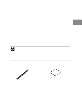
In the Box
EN
Heat-shrink×1430 Lite ESC×1
5
Page 8
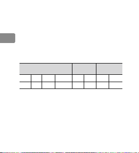
Gain Value Settings
The 430 Lite ESC features a square wave drive. To
achieve optimal sensitivity, adjust the gain values
EN
according to your ight control system and frame
before use. The table below shows typical gain
values used with the DJI NAZA
system and the DJI F450 multirotor ying platform,
at a takeoff weight of 1.3 kg.
Basic Attitude
Pitch Roll Yaw Vertical Pitch Roll Pitch Roll
85% 85% 100% 100% 95% 95% 300 300
Connecting the ESCs
Tools Required: Power distribution board (PDB),
electric soldering iron and soldering tin.
1. Solder the black GND cable and white VCC cable of
the ESCs to the pads on the PDB as shown. Make
sure the solder is rmly attached to the power pads
and that there is no possibility for a short circuit.
6
TM
-M V2 ight control
Max Angular
Velocity
Page 9
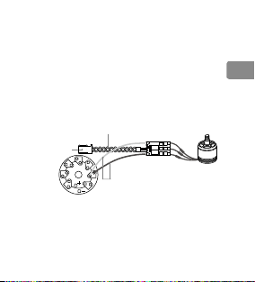
2. Connect the signal cable to your ight controller.
The signal cable’s white wire transmits the control
signal; the black wire is for GND.
3. Connect the motor to the ESC. Test the motors and
ensure that the rotation direction of each motor is
correct. You can reverse the rotation direction by
swapping the positions of any two cables.
4. A PWM signal cable is also used to connect to a
PC to update rmware.
PDB
Signal Cable
Power Cables
ESC
Motor
Connecting to the
ight controller
The outer power pads are for the black GND cables.
The inner power pads are for the white VCC cables.
Make sure you solder them correctly. Try to solder
EN
7
Page 10
the cables firmly to the power hub at the proper
length (the wires should be just long enough to reach
the soldering point, facing outwards, and should not
EN
be bunched up in front of the soldering point).
Ensure that there are no open circuits or
exposed wires when soldering the ESC cables.
•
It is recommended that you solder a power
connector onto the power hub.
•
DJI will release rmware updates when
available. Please refer to the ofcial DJI
website. An ESC Programmer is required for
ESC rmware updates. Please purchase this
from the DJI Online Store. Please refer to the
DJI Snail ESC Programmer User Guide for
details on rmware updates.
8
Page 11

Description of Sound System
The ESC will beep when in use. The table below
contains more information about the warning sound.
Normal Description
Chime
Abnormal Description
Rapid Beep Minimum throttle signal not reached.
Single Beep No signal
Double Beep Motor Stalled
Ready
Check the flight controller, remote
controller, or remote controller receiver.
Specications
Maximum Allowable Voltage 17.4 V
Maximum Allowable Current
(continuous)
Maximum Peak Current* (3 sec) 45 A
*Tested at well ventilated temperatures of 25℃.
30 A
EN
9
Page 12

PWM Input Signal Level 3.3 V/5 V Compatible
Signal Frequency 30 ~ 500 Hz
Battery 3S ~ 4S LiPo
EN
Weight (without cables) 2.8 g
Weight (with cables) 11.6 g
This content is subject to change.
Download the latest version from
http://www.dji.com/e305
DJI is a trademark of DJI.
Copyright © 2017 DJI All Rights Reserved.
Page 13

免责声明
感谢您购买 DJI
使用之前,请仔细阅读本声明,一旦使用,即被视为
对本声明全部内容的认可和接受。请严格遵守说明安
装和使用该产品。因用户不当使用、安装、改装(包
括使用非指定的 DJI 零配件,如:电机、螺旋桨等)
造成的任何损失,深圳市大疆 ™ 创新科技有限公司
及其关联公司将不承担任何责任。
DJI 是深圳市大疆创新科技有限公司及其关联公司的
商标。本文出现的产品名称、品牌等,均为其所属公
司的商标或注册商标。本产品及说明为深圳市大疆创
新科技有限公司版权所有。未经许可,不得以任何形
式复制翻印。
关于不同语言版本的免责声明可能存在的语义差异,
中国以中文版为准,其他地区以英文版为准。
产品使用注意事项
1. 使用时请远离不安全因素,如障碍物、人群、高压
2. 切勿贴近或接触旋转中的电机或螺旋桨,避免被旋
TM
430 Lite 电调(电子调速器)。在
线等。
转中的螺旋桨割伤。
CHS
11
Page 14

3. 确保电调焊接正确,电路无短路、无开路。
4. 使用前请检查螺旋桨和电机是否安装正确。
5. 使用前请检查各零部件是否完好。如有部件老化或
损坏,请更换新部件。
6. 每次飞行前,请检查飞行器各部分结构及螺丝是否
CHS
松动。
7. 由于电调默认带主动刹车功能,请勿使用直流稳压
电源连接电调进行测试,否则将导致电调以及电源
损坏。
8. 请严格按照本文规定的工作环境(如电压、电流等
参数)使用,否则将会对产品造成永久性损坏。
9. DJI 430 Lite 电调务必和同款电调搭配使用。
简 介
DJI 430 Lite 电调采用方波驱动,功能更加简化,外
形小巧轻便,可满足用户的不同需求。内置高效、快
速响应算法,能有效让飞行器姿态调整更加迅速,下
降更平稳。430 Lite 电调支持DJI ASSISTANT
参软件进行升级,方便用户享受未来更多新功能。
12
TM
2 调
Page 15

产品特性
支持主动刹车功能
支持最高转速电机
46000 rpm(7 对极电机)
322000 rpm(1 对极电机)
最高 30A 持续电流
支持 DJI Assistant 2 PC 调参
完整的电磁兼容性测试
辐射骚扰测试
静电抗扰度测试
射频电磁场辐射抗扰度测试
主动刹车:电机主动提供反向力矩来使螺旋桨
减速,同时将螺旋桨的转动动能转移至电池或
其他电机上。若关闭主动刹车功能,螺旋桨减
速将主要通过桨叶的空气阻力实现。
物品清单
CHS
备用热缩套 ×1430 Lite电调 ×1
13
Page 16

参数感度调节
430 Lite 电调采用方波驱动,使用前,用户需要根据
所使用的机架及飞控系统调节参数感度。下表是配合
TM
DJI NAZA
-M V2 飞控系统和DJI F450 多旋翼飞行
平台使用,起飞重量为 1.3 kg 时的组典型参数。
CHS
基本感度 姿态感度 最大角速度
俯仰 横滚 航向 垂直 俯仰 横滚 俯仰 横滚
85% 85% 100% 100% 95% 95% 300 300
安装连线
工具和材料(自备):分电板、电烙铁和焊锡。
1. 将电调电源线焊到分电板上,注意焊点牢固并且不
会出现短路。电源线白色为电源 VCC,黑色为地
GND。
2. 将电调 PWM 信号线连接至飞控。其中白色线为控
制信号线,黑色线为地线。
3. 将电机的三根线分别连到电调上。调试使电机按照
需求方向旋转。如果不一致,交换该电机的任意两
根连线。
4. 电调 PWM 信号线同时用于固件升级。
14
Page 17

电调 PWM信号线
连接至飞控
分电板
分电板内圈焊盘为电源 VCC,外圈焊盘为地 GND。
剥开一段电源线,长度刚好够焊接到板上即可,焊接
时请注意将线焊接到正确的电极上,焊接后电源线朝
向板外侧(如图所示),并且线能平贴在分电板上。
请确保电路中没有短路或者开路。
•
建议您将电池转接头焊接到分电板上。
•
若 430 Lite 电调固件需要升级,DJI 官网将发
布固件升级程序,请留意产品下载页面。电调
升级需要使用 DJI Snail 电调编程器(需自行
购买)。具体升级方法请参考《DJI Snail 电
调编程器使用说明》。
电源线
电调
电机
CHS
15
Page 18

电调提示音描述
使用时,请根据电调鸣音判断产品是否正常工作。如
果出现异常状态鸣音,请排查故障。
正常状态鸣音 描述
CHS
开机音
异常状态鸣音 描述
BBBB…
B--B--B… 无油门输入
B---B-B---B 电机堵转
准备就绪
油门输入不在最小值,请检查
飞控、接收机或遥控器设置
产品规格
最大允许电压 17.4 V
最大允许电流(持续) 30 A
最大允许峰值电流 *(3 秒) 45 A
* 25℃通风良好情况测得数据
16
Page 19

PWM 输入信号电平 3.3 V/5 V 兼容
兼容信号频率 30 ~ 500 Hz
电池 3S ~ 4S LiPo
默认输出 PWM 频率 16 kHz
重量(不含线) 2.8 g
重量(含线) 11.6 g
内容如有更新,恕不另行通知。
您可以在 DJI 官方网站查询最新版本
http://www.dji.com/e305
DJI 是大疆创新的商标。
Copyright © 2017 大疆创新 版权所有
CHS
Page 20

Haftungsausschluss
Vielen Dank, dass Sie sich für den Kauf des DJITM 430 Lite
ESC (im Folgenden als „das Produkt“ bezeichnet) entschieden
haben. Bitte lesen Sie sich diesen Haftungsausschluss
aufmerksam durch, bevor Sie das Produkt verwenden.
Durch die Verwendung dieses Produkts erklären Sie sich mit
DE
diesem Haftungsausschluss einverstanden und bestätigen,
dass Sie ihn vollständig gelesen haben. Montieren und
verwenden Sie dieses Produkt unter strikter Beachtung
der Bedienungsanleitung. Die SZ DJI TECHNOLOGY CO.,
LTD., und ihre verbundenen Unternehmen übernehmen
keine Haftung für Schäden oder Verletzungen, die direkt
oder indirekt aus unsachgemäßer Nutzung, Montage oder
Modizierung dieses Produkts entstehen, einschließlich, der
Verwendung von nicht vorgesehenem Zubehör.
DJI ist eine Marke der SZ DJI TECHNOLOGY CO., LTD. (kurz
DJI) und seiner verbundenen Unternehmen. Namen von
Produkten, Marken, usw., die in dieser Bedienungsanleitung
enthalten sind, sind Warenzeichen oder eingetragene
Warenzeichen der jeweiligen Besitzer. Dieses Produkt und
die Bedienungsanleitung sind urheberrechtlich geschütztes
Eigentum von DJI und alle Rechte sind vorbehalten. Kein
Teil dieses Produkts oder der Bedienungsanleitung darf in
irgendeiner Form ohne die vorherige schriftliche Zustimmung
oder Genehmigung durch DJI reproduziert werden.
18
Page 21

Dieser Haftungsausschluss existiert in verschiedenen
Sprachen. Im Falle von Abweichungen zwischen den
verschiedenen Versionen ist die chinesische Version
maßgeblich, wenn das fragliche Produkt in China
erworben wurde, bzw. die englische Version, wenn das
fragliche Produkt in anderen Regionen erworben wurde.
Warnung
1. Verwenden Sie Ihr Fluggerät stets in Bereichen, die
frei von Menschen, Tieren, Stromleitungen und andere
Hindernissen sind.
2. Sie sollten sich den Motoren oder den Propellern NICHT
nähern oder sie berühren, wenn das Gerät eingeschaltet ist.
3. Stellen Sie sicher, dass keine Schaltkreisunterbrechungen
oder Kurzschlüsse vorhanden sind, wenn Sie die ESCKabel (die Kabel des elektronischen Drehzahlreglers)
löten.
4. Stellen Sie vor dem Start sicher, dass die Propeller und
Motoren richtig montiert sind.
5. Stellen Sie sicher, dass alle Teile des Fluggeräts in gutem
Zustand sind. Fliegen Sie NICHT mit abgenutzten oder
beschädigten Teilen.
6. Stellen Sie vor jedem Flug sicher, dass alle Teile gut
befestigt und alle Schrauben fest angezogen sind.
DE
19
Page 22

7. Schließen Sie den elektronischen Drehzahlregler (ESC)
NICHT an eine geregelte Gleichstromversorgung an,
da ansonsten das Stromversorgungssystem und der
elektronische Drehzahlregler beschädigt werden, wenn
das Produkt die Energie aufnimmt, die beim Verzögern
produziert wird, da dieses Produkt standardmäßig mit
einer aktiven Bremsfunktion ausgestattet ist.
DE
8. Stellen Sie sicher, dass Sie das Produkt in strikter
Übereinstimmung mit den in diesem Dokument aufgeführten
Spezifikationen (Spannungs-/Stromstärke, Temperatur,
usw.) verwenden. Andernfalls kann es zu permanenten
Schäden am Produkt kommen.
9. Verwenden den DJI 430 Lite ESC NICHT mit ESCs
anderer Serien.
Einleitung
Der DJI 430 Lite ESC setzt einen Rechteckwellen-Antrieb,
der einfache Funktionen unterstützt, die die spezischen
Anforderungen des Benutzers erfüllen. Im Inneren sorgt
ein effizienter und reaktionsschneller Algorithmus für
Manövrierfähigkeit und Stabilität, die bei dieser Größe
sonst kaum zu erreichen wäre. Wie die meisten DJIProdukte kann auch die ESC-Firmware aktualisiert werden,
um sicherzustellen, dass der 430 Lite ESC immer optimal
abgestimmt ist.
20
Page 23

Eigenschaften
• Aktive Bremsfunktion
• Motoren mit hohen Drehzahlen
46.000 U/min (7 Polpaare)
322.000 U/min (1 Polpaar)
• Maximaler Dauerstrom: 30 A
• DJI ASSISTANTTM 2 Software
• Umfassende Prüfung der elektromagnetischen Kompatibilität
Störabstrahlung
Immunität gegen elektrostatische Entladung
Immunität gegen elektromagnetische Felder (abgestrahlte
Frequenz)
Aktive Bremsfunktion: Der Motor dreht das Drehmoment
beim Verzögern aktiv um und gewinnt so einen Teil der
Drehenergie zurück. Bei normalen Bremsvorgängen
wird hauptsächlich der Luftwiderstand genutzt.
Lieferumfang
DE
430 Lite ESC × 1
Wärmeschrumpfelement × 1
21
Page 24

Einstellungen der Verstärkungswerte
Der 430 Lite ESC verfügt über einen Rechteckwellenantrieb.
Zum Erreichen der optimalen Empfindlichkeit stellen
Sie die Verstärkungswerte vor dem Betrieb auf Ihr
Flugsteuerungssystem ein. In der Tabelle unten finden
Sie einige typische Verstärkungswerte für ein DJI
DE
NAZATM-M V2 Flugsteuerungssystem und einer DJI F450
Multirotorplattform mit einem Startgewicht von 1,3 kg.
Basis Fluglage
Nicken Rollen Gieren Vertikal Nicken Rollen Nicken Rollen
85 % 85 % 100 % 100 % 95 % 95 % 300 300
Anschließen der ESCs
Benötigte Werkzeuge: Stromkreisverteiler, Lötkolben und
Lötzinn
1. Löten Sie das schwarze GND-Kabel und das weiße
VCC-Kabel des ESC wie gezeigt an den Platten am
Stromkreisverteiler an. Vergewissern Sie sich, dass der
Lötzinn fest an den Platten sitzt und dass es nicht zu
einem Kurzschluss kommen kann.
22
Max. Winkelge-
schwindigkeit
Page 25

2. Schließen Sie das Signalkabel an Ihren Flugregler
an. Über die weiße Ader des Signalkabels wird das
Steuerungssignal übertragen, die schwarze Ader dient
zur Erdung (GND).
3. Schließen Sie den Motor an den ESC an. Testen Sie die
Motoren, und stellen Sie sicher, dass die Drehrichtung
aller Motoren korrekt ist. Sie können die Drehrichtung
durch Tauschen der beiden Kabel umkehren.
4. Außerdem wird ein PWM-Signalkabel verwendet, um den
PC zur Aktualisierung der Firmware anzuschließen.
Stromkreisverteiler
Signalkabel
Netzkabel
ESC
Motor
Anschließen an die
Flugsteuerung
DE
23
Page 26

Die äußeren Stromplatten sind für die schwarzen GNDKabel. Die inneren Stromplatten sind für die weißen VCCKabel. Achten Sie beim Löten darauf, dass die Kabel an
die korrekten Platten gelötet werden. Löten Sie die Kabel in
der passenden Länge an den Stromplatten fest (die Kabel
sollten gerade zu den Lötstellen reichen und nicht vor den
Lötstellen zusammengeknüllt sein).
DE
Stellen Sie sicher, dass keine
Schaltkreisunterbrechungen oder freiliegenden Drähte
vorhanden sind, wenn Sie die ESC-Kabel löten.
•
Es wird empfohlen einen Stromanschluss auf den
Stromverteiler zu löten.
•
DJI gibt Firmware-Aktualisierungen heraus, wenn
diese zur Verfügung stehen. Besuchen Sie hierzu
die ofzielle DJI Website. Für die Aktualisierung
der ESC-Firmware wird ein ESC-Programmierer
benötigt. Sie können diesen im DJI Webshop
erstehen. Nähere Informationen zu FirmwareUpdates finden Sie in der Bedienungsanleitung
des DJI Snail ESC-Programmierers.
24
Page 27

Beschreibung des Soundsystems
Der ESC gibt einen Signalton ab, wenn er benutzt wird.
Der Signalton wird in der Tabelle unten näher beschrieben.
Normal Beschreibung
Klingeln
Abnormal Beschreibung
Schnelles
Piepen
Einzelner
Piepton
Doppelter
Piepton
Bereit
Minimales Beschleunigungssignal nicht
erreicht. Prüfen Sie die Flugsteuerung,
die Fernbedienung und den Empfänger
der Fernbedienung.
Kein Signal
Motor ausgefallen
DE
25
Page 28

Technische Daten
Max. zulässige Spannung 17,4 V
Max. zulässige Stromstärke
(Dauerstrom)
Max. Spitzenstromstärke* (3 Sek.) 45 A
DE
PWM-Eingangssignalstärke 3,3 V/5 V kompatibel
Signalfrequenz 30 – 500 Hz
Akku 3S – 4S LiPo
Gewicht (ohne Kabel) 2,8 g
Gewicht (mit Kabeln) 11,6 g
*In gut ventilierter Umgebung bei 25 °C getestet.
Änderungen vorbehalten.
Die aktuelle Fassung nden Sie unter
http://www.dji.com/e305
DJI ist eine Marke von DJI.
Copyright © 2017 DJI Alle Rechte vorbehalten.
30 A
Page 29

Compliance Information
FCC Compliance
This device complies with Part 15 of the FCC Rules.
Operation is subject to the following two conditions:
(1) This device may not cause harmful interference, and
(2) This device must accept any interference received,
including interference that may cause undesired operation.
Any changes or modications not expressly approved by
the party responsible for compliance could void the user’s
authority to operate the equipment.
EU Compliance Statement: SZ DJI TECHNOLOGY CO.,
LTD. hereby declares that this device is in compliance with
the essential requirements and other relevant provisions of
the EMC Directive.
A copy of the EU Declaration of Conformity is available online
at HYPERLINK "http://www.dji.com/euro-compliance" www.
dji.com/euro-compliance
EU-Compliance: Hiermit erklärt SZ DJI TECHNOLOGY CO.,
LTD., dass dieses Gerät den wesentlichen Anforderungen
und anderen einschlägigen Bestimmungen der EU-Richtlinie
EMC entspricht.
27
Page 30

Eine Kopie der EU-Konformitätserklärung nden Sie online
auf www.dji.com/euro-compliance.
EU contact address: DJI GmbH, Industriestrasse. 12, 97618,
Niederlauer, Germany
28
Page 31

Page 32

DJI Support
DJI
技术支持
DJI Support
http://www.dji.com/support
If you have any questions about this document,
please contact DJI by sending a message to
DocSupport@dji.com
如果您对说明书有任何疑问或建议,请通过以
下电子邮箱联系我们:
.
DocSupport@dji.com
Printed in China.
。
中国印制
 Loading...