


IMPORTANT - READ CAREFULLY
The Dixon® ZTR® Mower is both easy and fun to operate. However, any power mower must be operated properly to be safe. It is not a toy or a recreational vehicle. Before you start to use the mower, read the operator's manual carefully and become completely familiar with the controls.
The information in this operator's manual applies to all Dixon@ZTR@5000 Series Model Mowers. Your Dixon dealer will gladly provide a check-out ride and answer any questions.
See your dealer for warranty service, parts and repairs.
DIXON INDUSTRIES, INC A BLOUNT COMPANY
AIRPORT INDUSTRIAL PARK PO BOX 1569
COFFEYVILLE KS 67337 O945 316 251 2OOO
FAX 316 251 4117

INDEX
SAFETY ............................................................ |
Pages |
1 - 6 |
WARRANTY POLICY......................................... |
Page |
7 |
SPECIFICATIONS.............................................. |
Page |
8 - 1 0 |
SEAT ADJUSTMENT ......................................... |
Page |
11 |
CONTROLS....................................................... |
Pages 1215 |
|
OPERATION INSTRUCTIONS ............................ |
Pages 1623 |
|
CARE AND MAINTENANCE............................... |
Pages 24 - 38 |
|
STANDARD SERVICE PARTS LIST .................... |
Page |
39 - 40 |
TROUBLESHOOTING ........................................ |
Pages 41 -43 |
|
DIAGRAMS........................................................ |
Pages 4462 |
|
Part No. 8965
September 1995
 SAFETY
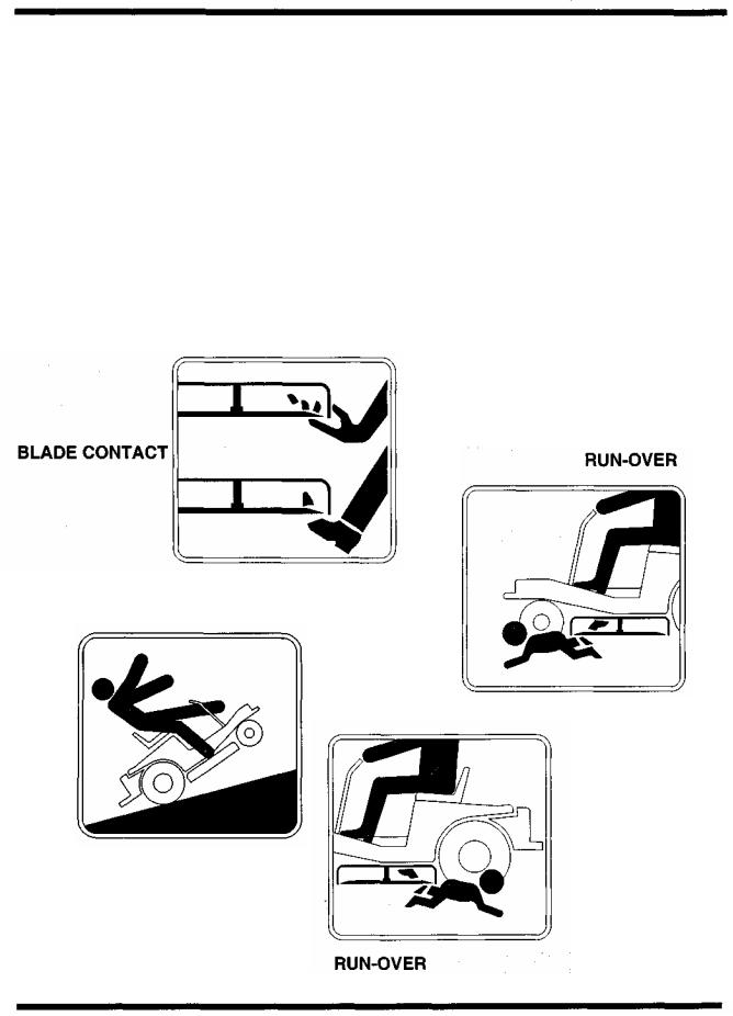
RIDING LAWNMOWERS, IF IMPROPERLY OPERATED, CAN CAUSE SERIOUS INJURY OR DEATH
The most common causes of injury to the operator or bystander...
TIP-OVER
Page 1
 SAFETY
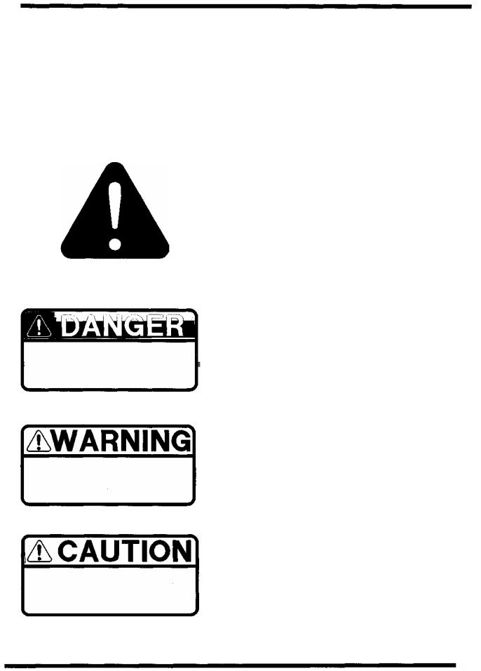
SAFETY SYMBOLS:
SAFETY ALERT SYMBOL -
When you see this symbol,
BE ALERT to the potential for injury.
Follow recommended safety precautions and safe operating practices.
Danger indicates an imminently hazardous situation which, if not avoided, will result in death or serious injury.
Warning indicates a potentially hazardous situation which, if not avoided, could result in death or serious injury.
Caution indicates a potentially hazardous situation which, if not avoided, may result in minor or moderate injury. It may also be used to alert against unsafe practices.
Page 2

This cutting mower is capable of amputating hands and feet, and throwing objects. Failure to observe the following safety instructions could result in
serious injury or death.
GENERAL OPERATION:
*Read, understand, and follow all instructions in the manual and on the mower before starting.
*Only allow responsible adults, who are familiar with the instructions, to operate the mower.
*Clear the area of objects such as rocks, toys, wire, etc., which could be picked up and thrown by the blade.
*Be sure the area is clear of other people before mowing. Stop mower if anyone enters the area.
*Never carry passengers.
*Do not mow in reverse unless absolutely necessary. Always look down and behind before and while backing.
*Be aware of the mower discharge direction and do not point it at anyone. Do not operate the mower without either the entire grass catcher or the deflector in place.
*Slow down before turning.
*Never leave a running mower unattended. Always turn off blades, set parking brake, stop engine, and remove key before dismounting.
*Turn off blades when not mowing.
*Stop engine before removing grass catcher or unclogging chute.
*Mow only in daylight or good artificial light.
*Do not operate the mower while under the influence of alcohol or drugs.
*Watch for traffic when operating near or crossing roadways.
*Use extra care when loading or unloading the mower into a trailer or truck. Do not ride the mower when loading & unloading.
The Engine Exhaust from this product contains chemicals known to the
State of California to cause cancer, birth defects or other reproductive harm.
Page3

 SAFETY
SLOPE OPERATION:
Slopes are a major factor related to loss-of-control and tip-over accidents, 'which can result in severe injury or death.
All slopes require extra caution. -.
If you cannot back up the slope or if you feel uneasy on it, do not mow it.
DO
Mow across the slope with your Dixon ZTR - never up or down.
Remove obstacles such as rocks, tree limbs, etc.
Watch for holes, ruts or bumps. Uneven terrain could overturn the mower. Tall grass can hide obstacles.
Use slow speed.
Use extra care with grass catchers or other attachments. These can change the stability of the mower.
Keep all movement on the slopes slow and gradual. Do not make sudden changes in speed or direction.
Avoid starting or stopping on a slope. If tires lose traction, disengage the blades and proceed slowly down the slope.
DO NOT
Do not turn on slopes unless necessary, and then, turn slowly and gradually downhill, if possible.
Do not mow near drop-offs, ditches, or embankments. The mower could suddenly turn over if a wheel is over the edge of a cliff or ditch, or if an edge caves in.
Do not mow on wet grass. Reduced traction could cause sliding.
Do not try to stabilize the mower by putting your foot on the ground..
Do not use grass catcher on steep slopes.
Page 4

 SAFETY
CHILDREN:
Tragic accidents can occur if the operator is not alert to the presence of children.
Children are attracted to lawn mowers and the mowing activity.
NEVER assume children will stay where they were last seen.
Be alert to avoid accidents.
∙Keep children out of the mowing area and under the watchful care of another responsible adult.
•Be alert and turn mower off if a child enters the area.
•Before and during backing, look behind and DOWN for small children.
•Never carry children. They may fall off and be seriously injured or interfere with safe mower operation.
•Never allow children to operate the mower.
•Use extra care when approaching blind corners, shrubs, trees, or other objects that may obscure vision.
Page 5

 SAFETY
SERVICE:
• Use extra care in handling gasoline and other fuels. They are flammable and vapors are explosive.
Use only an approved container.
Never remove gas cap or add fuel with the engine running. Allow engine to cool before refueling. Do not smoke.
Never refuel the mower indoors.
Never store the mower or fuel container inside a building where there is an open flame.
•Never run a mower inside a closed area.
•Keep nuts and bolts, especially blade attachment bolts, tight and keep equipment in good condition.
•Never tamper with safety devices. Check their proper operation regularly.
•Keep mower free of grass, leaves, or other debris buildup. Clean up oil or fuel spillage. Allow mower to cool before storing.
•Stop and inspect the equipment if you strike an object. Repair, if necessary, before restarting.
•Never make adjustments or repairs with the engine running.
•Grass catcher components are subject to wear, damage, and deterioration, which could expose moving parts or allow objects to be thrown. Frequently check components and replace with original equipment parts, when necessary.
•Mower blades are sharp and can cut. Wrap the blade(s) or wear gloves, and use extra caution when servicing them.
•Batteries contain sulfuric acid. To prevent burns avoid contact with skin, eyes and clothing. To prevent a fire or explosion keep sparks and open flames away from battery.
Before disconnecting the negative (-) ground cable, make sure all switches are OFF.
•Check to assure that the drive chains are properly adjusted. A loose chain may come off causing loss of control. This statement applies to chain drive models 2301, 3000 & 4000 Series.
Page 6

DIXON LIMITED WARRANTY POLICY -- HYDRO-GEAR MODELS
This warranty policy applies to all HydroGear mowers or any 50" model, purchased on or after March 1,1990.
WARRANTY: Dixon Warranty term is for a period of one (1) year from date of purchase or 400 hours of use, whichever occurs first. Mowers used for residential homeowner applications (used only at owner's primary place of residence) are warranted for two (2) years from date of purchase or 400 hours of use, whichever occurs first. DIXON ZTR MOWERS ARE WARRANTED AGAINST DEFECTS IN MATERIALS AND WORKMANSHI P AND PROVIDES FOR REPLACEMENT OR REPAIR OF PARTS INCLUDING LABOR COSTS. THIS WARRANTY IS SUBJECT TO THE FOLLOWING CONDITIONS AND LIMITATIONS:
1.Warranty applies only to original retail purchaser of new and unused mowers and accessories.
2.All Dixon warranty must be accomplished by authorized Dixon dealers and in accordance with Dixon warranty policy and allowances. All warranty claims must be approved by Dixon Industries, Inc.
3.Battery warranty: Limited to 90 days from date of purchase.
4.Accessories Warranty (Grass Catchers, Snow Blades, Tine Rakes, Covers, etc.): Limited to 90 days from date of purchase.
5.Warranty does not apply to damage in transit or incidents of misuse, negligence, accidents, or alteration. The use of parts or components other than those supplied by Dixon Industries, Inc. VOIDS ALL WARRANTY.
6.The following items are noLcovered by this warranty policy:
(a)Pick up and delivery charges for transportation of mower to and from an Authorized Dixon Dealer's place of business.
(b)Routine maintenance or adjustments.
(c)Belts / chains / sprockets / cutting blades.
(d)Engines -- All engines used on Dixon ZTR mowers are warranted by each individual engine manufacturer.
(e)Any costs or expense of providing substitute equipment while repair work is being performed on a warranted mower.
7.There is no other express warranty. Implied warranties, including those of merchantability and fitness for a particular purpose, are limited to the same duration of the express warranty, and to the extent permitted by law any and all implied warranties are excluded. Liabilities for consequential damages under any and all warranties are excluded.
WARRANTY VALIDATION: At the time of sale, selling dealer must review each portion of this warranty document, complete the information section below, secure customer's signature and send copy to Dixon Industries, Inc.
Page 7
SPECIFICATIONS
Model ZTR 5422
CHASSIS:
BODY:
11 GA - rectangular tube
Two piece - made of rotational molded polyethylene. Front body contains access panels for battery service and engine to mower deck belt removal. Rear body tilts up to allow service on the entire drive system.
SEAT: |
Designed for operator comfort by use of high density closed cell foam padded |
|
back and arm rests. Seat is adjustable fore and aft. |
MOWER DECK: |
13 GA stamped steel construction |
|
3 blades combine for a 42" cut width |
|
Cut height approximately 1 .5" to 4.5" via 7 position lift handle |
BLADE DRIVE: |
Electric clutch |
DRIVE SYSTEM: |
Each rear wheel is independently driven by a HydroGear BDU-10L Series 70 |
|
hydrostatic transmission. The hydrostatic transmissions, in turn, power a fully |
|
enclosed HydroGear gearbox. |
ENGINE: |
1 6 HP Kohler Magnum, Vertical Crankshaft, 4-Cycle, Air Cooled, Gasoline, Twin |
|
CylinderOpposed, Aluminum Crankcase, Removable Cast Iron Cylinder Barrels, |
|
Electronic Ignition, Full Pressure Lubrication. |
STARTING SYSTEM:
TIRES:
RECOMMENDED TIRE PRESSURE: -^ CAPACITIES:
DIMENSIONS:
N
Electric by key switch operation with safety interlocks on parking brake and blade drive clutch.
Front |
11 X 4 X 5 smooth profile |
Rear |
18 X 9.5 X 8 Multi Trac |
Front |
16-21 Ibs. |
Rear |
8 - 1 4 Ibs, |
Fuel - 4.8 gallons total (dual tanks)
Hydrostat oil tank - 3 quart with in-line 10 micron filter
Hydrostat oil recommendation, refer to page 37
Engine - 2 qts. SAE 30 (with filter)
Width |
51" |
|
|
Height |
45" |
: |
. |
|
|||
. Length |
72" |
|
|
Weight |
61 5 Ibs. |
|
|
NOTE: Additional information provided in service instructions under the individual component.
SPECIFICATIONS SUBJECT TO CHANGE WITHOUT NOTICE
Page 8

CHASSIS:
BODY:
SEAT:
MOWER DECK:
BLADE DRIVE:
DRIVE SYSTEM:
ENGINE:
STARTING SYSTEM:
TIRES:
RECOMMENDED TIRE PRESSURE: CAPACITIES:
DIMENSIONS:
NOTE:
SPECIFICATIONS
Model ZTR 5502
1 1 GA - rectangular tube
Two piece - made of rotational molded polyethylene. Front body contains access panels for battery service and engine to mower deck belt removal. Rear body tilts up to allow service on the entire drive system.
Ergonomically designed for operator comfort by use of high density closed cell foam, contoured back rest and arm rests. Seat is adjustable fore and aft.
1 1 GA fabricated welded construction with external reinforcement ribs
3 blades combine for a 50" cut width
Cut height approximately 1 .5" to 4.5" via 8 position lift handle
Electric clutch
Each rear wheel is independently driven by a HydroGear BDU-10L Series 70 hydrostatic transmission. The hydrostatic transmissions, in turn, power a fully enclosed HydroGear gearbox.
20 HP Kohler Magnum, Vertical Crankshaft, 4-Cycle, Air Cooled, Gasoline, Twin CylinderOpposed, Aluminum Crankcase, Removable Cast Iron Cylinder Barrels, Electronic Ignition, Full Pressure Lubrication.
Electric by key switch operation with safety interlocks on parking brake and blade drive clutch.
Front |
11 X 4 |
X 5 smooth profile |
Rear |
20 X 1 0 X 8 Multi Trac |
|
Front |
16-21 |
Ibs. |
Rear |
8- 14 |
Ibs. |
Fuel - 4.8 gallons total (dual tanks)
Hydrostat oil tank - 3 quart with in-line 10 micron filter
Hydrostat oil recommendation, refer to page 37
Engine - 2 qts. SAE 30 (with filter)
Width |
60" |
Height |
45" |
Length |
72" |
Weight |
680 Ibs. |
Additional information provided in service instructions under the individual component.
SPECIFICATIONS SUBJECT TO CHANGE WITHOUT NOTICE
Page 9

|
SPECIFICATIONS |
|
|
|
Model ZTR 5601 |
CHASSIS: |
11 GA - rectangular tube |
|
BODY: |
Two piece - made of rotational molded polyethylene. Front body contains |
|
|
access panels for battery service and engine to mower deck belt removal. Rear |
|
|
body tilts up to allow service on the entire drive system. |
|
SEAT: |
Ergonomically designed for operator comfort by use of high density closed cell |
|
|
foam, contoured back rest and arm rests. Seat is adjustable fore and aft. |
|
MOWER DECK: |
10 GA stamped steel construction |
|
|
3 blades combine for 60" cut width |
|
|
Cut height approximately 1" to 4" via 8 position lift handle |
|
BLADE DRIVE: |
Electric clutch |
|
DRIVE SYSTEM: |
Each rear wheel is independently driven by a HydroGear BDU-10L Series 70 |
|
|
hydrostatic transmission. The hydrostatic transmissions, in turn, power a fully |
|
|
enclosed HydroGear gearbox. |
|
ENGINE: |
22 HP Kohler Command, 4-Cycle, Twin Cylinder, V-Configuration, Overhead |
|
|
Valve, Air-Cooled, Gasoline, Vertical Shaft, Aluminum Head and Crankcase with |
|
|
Cast Iron Liners, Oil Cooler. |
|
STARTING SYSTEM: |
Electric by key switch operation with safety interlocks on parking brake and blade |
|
|
drive clutch. |
|
TIRES: |
Front |
1 1 X 4 X 5 ribbed tread |
|
Rear |
20 X 10X8 Muiti Trac |
RECOMMENDED |
Front |
16-21 Ibs. |
TIRE PRESSURE: - |
Rear |
8- 14 Ibs. |
CAPACITIES: |
Fuel - 4.8 gallons total (dual tanks) |
|
|
Hydrostat oil tank - 3 quart with in-line 10 micron filter |
|
|
Hydrostat oil recommendation, refer to page 37 |
|
|
Engine - 2 qts. SAE 10W30 (with filter) |
|
DIMENSIONS: |
Width |
72" |
|
Height |
45" |
|
Length |
72" |
|
Weight |
685 Ibs. |
NOTE: |
Additional information provided in service instructions under the individual |
|
|
component. |
|
SPECIFICATIONS SUBJECT TO CHANGE WITHOUT NOTICE
Page 10
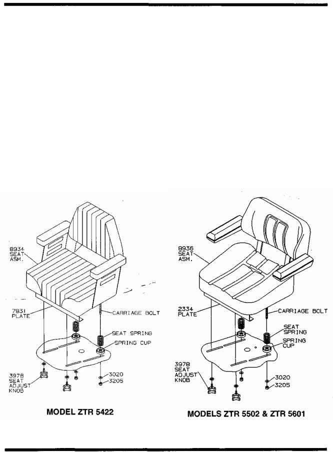
SEAT ADJUSTMENT INSTRUCTIONS
Models ZTR 5422 - ZTR 5502 - ZTR 5601 :
1.Place parking brake in ON position. (Pull brake lever up)
2.Raise and push seat assembly and upper body rearward.
3.Loosen two front seat adjustment knobs, P/N 3978, and slide seat forward or backward to desired position.
4.Re-tighten front seat adjustment knobs, P/N 3978.
DO NOT operate mower without seat adjustments properly tightened.
5.Carefully lower upper body and seat assembly to the closed position.
Page 11

Page 12
CONTROLS
CONTROLS
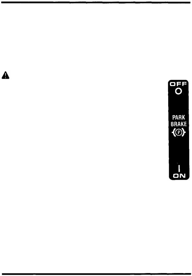
PARKING BRAKE:
The parking brake used on the 5000 Series Models is designed to hold the mower from moving and is not intended for use in stopping the mower while it is in motion.
CAUTION Engage parking brake before starting engine.
Do not leave engine running for extended periods of time without the parking brake engaged. Damage to the drive system could result.
TO SET PARKING BRAKE:
The hand operated parking brake is located at left hand side of mower.
To engage brake, pull lever up and to the rear. To release
brake, move lever forward and down. NOTE: Always set
parking brake before dismounting. Release parking brake
before moving mower.
HYDRO-GEAR DRIVE SYSTEM:
Allows the mower to turn on its own axis (zero turning radius).
Drive levers control braking, turning, travel speed and direction. Each lever controls one side of the mower.
NOTE: The pressure required to operate the mower is very light.
A minimum of 1/2 hour should be spent simply driving the mower without the blade drive engaged.
Page 13
CONTROLS
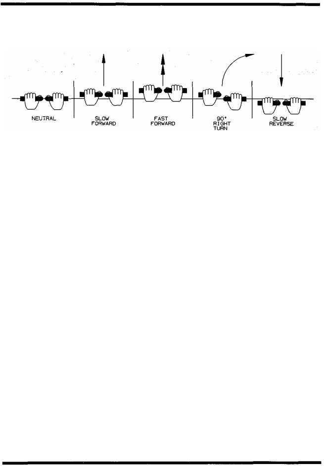
TO GO FORWARD:
From neutral position, gently push both drive levers forward.
To increase speed, move levers farther forward.
TO GO BACKWARD:
From neutral position, gently pull both drive levers toward you.
TURNING:
Turning is controlled by moving one drive lever slightly forward or rearward of the other.
To turn left, move left lever rearward of the right lever.
To turn "square corners" move lever of desired direction to neutral.
To turn on mower's own axis (zero turning radius) stop and move one lever to reverse position and the other to forward position. ,
BRAKING:
To brake mower, move both levers in direction opposite of travel, release levers to neutral, set parking brake. Park only on level surfaces.
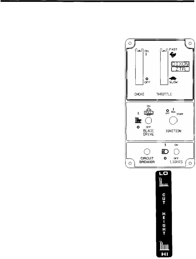
CHOKE CONTROL LEVER:
Located on control panel to operator's right.
Used to start a cold engine.
THROTTLE CONTROL LEVER:
Located on control panel to operator's right.
N
Controls engine speed, slow to maximum.
While mowing, throttle control shoujd be set to the MAXIMUM or wide open setting to insure adequate cooling of the engine and to maintain mower deck blade speed.
Page 14
CONTROLS
BLADE DRIVE:
Located on control panel, on operator's right.
To engage the mower blades, lift switch up lightly and push forward.
To disengage blades, pull switch backward.
Switch is clearly marked "on and off".
CIRCUIT BREAKER:
Located on control panel, on operator's right.
Protection of the electrical system is by (1)15 amp circuit breaker.
If circuit breaker trips, push button to reset.
If this condition repeats, consult dealer for inspection and repair.
MOWER DECK CUT HEIGHT LIFT LEVER:
Located to the right and front of operator.
Controls the cutting height.
Seven positions of adjustment, Model ZTR 5422.
Eight positions of adjustment, Model ZTR 5502 &
Model ZTR 5601.
Move lever in and forward to lower.
Move lever in and back to raise.
NOTE: Always use high position for transport.
Page 15

OPERATION INSTRUCTIONS
The safe and successful operation of the 5000 Series Models will depend upon the operator having the correct knowledge of all controls used on the mower and making good judgements about the terrain to be mowed.
NEVER allow anyone to operate the mower without complete knowledge of all controls and their functions.
During initial operation, "learning to drive", set throttle at slow speed.
Sound judgement by the owner will prevent accidents.
BEFORE OPERATING MOWER:
1. Read engine manufacturer's operating and maintenance instructions.
2.Discuss proper maintenance with your dealer.
3.Read and observe all safety instructions on your mower and in the manual.
4.Check engine oil.
5.Check gas cap to be sure it is in place.
6.Be sure parking brake is on.
7.Mower blade drive is off.
8.Know how to stop engine. (Turn key to off position)
Page 16

OPERATION INSTRUCTIONS
 TESTING OF SAFETY INTERLOCK SYSTEMS:
PARKING BRAKE SWITCH TEST: With parking brake in the OFF position, engine should not turn over or attempt to start when the key switch is moved to the start position.
BLADE DRIVE SWITCH TEST: (5000 Series)
a.With electric blade drive switch turned ON and parking brake in the ON position, engine should not turn over or attempt to start when key switch is moved to the start position.
b.In a SAFE AREA away from bystanders, start the engine, place throttle setting at maximum or full. Engage the blades by turning the blade drive switch to the ON position. Raise weight slightly off of seat.
Engine should stop.
c.If any Safety Check fails, do not operate the mower until the system has been checked and repaired by an Authorized Dixon ZTR Dealer.
OPERATION INSTRUCTIONS
STARTING INSTRUCTIONS: Cold Engine
1 . Push choke control lever fully forward.
2.Push throttle control lever to 1/2 setting.
3.Insert ignition key and turn to "Start" position. When engine starts, release ignition key. Key will return to "Run" position.
4.Once engine starts to warm up, slowly move choke control lever to the fully closed position.
5.Move throttle control lever to the wide open or maximum setting for actual operation of the mower deck.
6.Engine must be operated at wide open or maximum setting to insure adequate lubrication, cooling and cut quality of the mower deck.
NOTE: Model ZTR 5601 will require a slightly longer warm up period using partial choke settings.
Page 18

OPERATION INSTRUCTIONS
STARTING INSTRUCTIONS: |
Engine has been operated. |
1. Move throttle control lever to 1/4 to 1/2 setting.
2.Insert ignition key and turn to "Start" position. When engine starts, release ignition key. Key will return to "Run" position.
3.Move throttle control lever to wide open or maximum setting for actual operation of the mower deck.
NOTE: Model ZTR 5601 may require partial choke setting to start even if the engine has been operated for a period of time.
4.Engine must be operated at wide open or maximum setting to insure adequate lubrication, cooling and cut quality of the mower deck.
 CAUTION
DO NOT operate the engine in an enclosed area due to the harmful exhaust gas produced.
NOTE: On initial operation, set throttle at slow speed. Engine cannot be restarted when blade is engaged.
Safety switches stop engine when operator leaves seat while mower blade is engaged.
Always turn engine off when leaving mower.
Page 19
 Loading...