

Page 1
dIXEL
Installing and Operating Instructions
1598026100
1598026100 XR420C GB r1.0 22.02.2007.doc XR420C 1/4
XR420C
DUAL TEMPERATURE CONTROLLER
1. GENERAL WARNING
1.1 PLEASE READ BEFORE USING THIS MANUAL
• This manual is part of the product and should be kept near the instrument for easy and quick
reference.
• The instrument shall not be used for purposes different from those described hereunder. It
cannot be used as a safety device.
• Check the application limits before proceeding.
1.2
SAFETY PRECAUTIONS
• Check the supply voltage is correct before connecting the instrument.
• Do not expose to water or moisture: use the controller only within the operating limits avoiding
sudden temperature changes with high atmospheric humidity to prevent formation of
condensation
• Warning: disconnect all electrical connections before any kind of maintenance.
• Fit the probe where it is not accessible by the End User. The instrument must not be opened.
• In case of failure or faulty operation send the instrument back to the distributor or to “Dixell
S.p.A.” (see address) with a detailed description of the fault.
• Consider the maximum current which can be applied to each relay (see Technical Data).
• Ensure that the wires for probes, loads and the power supply are separated and far enough
from each other, without crossing or intertwining.
• In case of applications in industrial environments, the use of mains filters (our mod. FT1) in
parallel with inductive loads could be useful.
2. GENERAL DESCRIPTION
Model XR420C, 32x74 mm format, is a microcontroller based device, able to control 2 temperatures
in an independent way. Both sections are suitable for applications on normal or medium
temperature refrigerating units or cooking applications. It is provided with 3 relay outputs to control
two compressors and one light. Defrost process is performed through simple stop of compressors.
It is also provided with 2 NTC or PTC probe inputs, one for section 1 and the other one for section 2.
There is one digital input (free voltage contact) completely configurable by parameter. The standard
TTL output allows the user to connect, by means of a TTL/RS485 external module, a ModBUS-RTU
compatible monitoring system and to programme the parameter list with the “Hot Key”.
3. REGULATION
Two kinds of actions are available for both sections: cooling action and heating action. The type is
selected through cH1/cH2 section parameter.
3.1 HOW TO SET THE TYPE OF ACTION
By means of CH1/2 parameters the kind of action can be set for each section: cH1/cH2 = CL:
refrigerating action (1/2); cH1/cH2 = Ht: heating action (1/2)
3.2 CH1/CH2 = CL FOR COOLING ACTION
For each section, the regulation is
performed according to the
temperature measured by its own
thermostat probe with a positive
differential from the set point.
If the temperature increases and
reaches set point1 (2) plus
differential1 (2) the compressor is
started and then turned off when
the temperature reaches the set
point value again.
In case of fault in the thermostat probe the start and stop of
the compressor are timed through parameters “COn1(2)” and
“COF1(2)”.
3.3 CH1/CH2 = HT FOR HEATING ACTION
For each section, the regulation is performed
according to the temperature measured by its
own thermostat probe with a negative
differential from the set point. If temperature
decreases and reaches set point 1/2 minus
differential 1/2 the output is activated and then
turned off when the temperature reaches the
set point value again and then turned off when
the temperature reaches the set point value
again.
NOTE: For turn-off defrost you can set
MdF1/MdF2 = 0.
4. DEFROST
4.1 SECTION 1 (2)
Defrost is performed through a simple stop of the compressor for both sections. Different kinds of
defrosts are available for each section.
4.2 RELATION BETWEEN DEFROSTS
The relation between defrosts is set by the dFS parameter: relation between defrosts.
4 relation between the 2 sections of the controller are available, to manage different kinds for
applications:
- in = independent defrosts;
- StS = same defrost start, synchronised defrost end;
- St = same defrost start, independent defrost end;
- SE = sequential defrost;
4.2.1 dFS= in - independent defrosts
The defrosts of the 2 sections of controller are completely independent.
First section: defrost interval is set by idF1 parameter.
Second section: defrost interval is set by idF2 parameter.
The defrost interval is control by means of parameter “EdF1(2)”:
- in the defrost is made every “IdF1(2)” time
- Sd the interval “IdF1(2)” is calculate through Smart Defrost algorithm (only when the
compressor is ON)
Manual defrost activation, by pushing the DOWN key (defrost 1) or UP key (defrost 2).
By pushing the Down key or Up key for 3s, a defrost request is generated for section 1 or 2
respectively. The defrost interval is re-loaded.
4.2.2 dFS = StS – Same defrost start, end defrost synchronised or dFS = St
- Same defrost start, end defrost independent.
The defrost of the 2 sections of controller starts at the same time. idF1 parameter sets the defrost
interval for both the sections. The defrosts are performed at regular interval if EdF1 = in or according
to the Smartdefrost algorithm if EdF1 = Sd.
With dFS = StS regulation restarts only when defrost is finished for both the sections. The section
that finishes the defrost before the other starts dripping time until also the other section has not
finished its defrost.
Manual defrost activation, by pushing the DOWN key (defrost 1) or UP key (defrost 2).
By pushing the Down key or Up key for 3s, a defrost request is generated for both the sections 1
and 2.The defrost interval is re-loaded.
With dFS = St each section restarts regulation as soon as its defrost is finished.
4.2.3 dFS = SE – sequential defrost
The defrost of 2 sections is synchronised. idF1 parameter sets the defrost interval for both the
sections. Defrosts are performed at regular interval if EdF1 = in or according to the Smartdefrost
algorithm if EdF1 = Sd. Section 1 does its defrost first, at the end of the defrost of section 1, section
2 starts its defrost..
Manual defrost activation, by pushing the DOWN key (defrost 1) or UP key (defrost 2).
By pushing the Down key or Up key for 3s, a defrost request is generated for both the sections 1
and 2.The defrost interval is re-loaded.
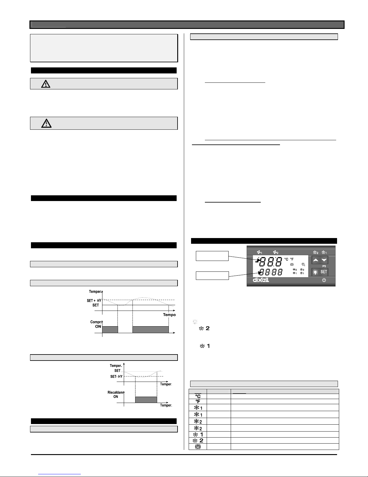
5. THE DISPLAY
X----C
XR400
The display is divided in 2 parts:
Upper left part: to see the temperature2 (upper display)
Lower left part: to see the temperature1(lower display)
SET To display and modify target set point 1 and set point 2, in programming mode it
selects a parameter or confirm an operation.
light activation/deactivation.
o/
(UP/DEFROST 2) in programming mode it browses the parameter codes or
increases the displayed value. By holding it pressed for 3s the defrost for section 2
is started
.
n/
(DOWN/DEFROST 1) in programming mode it browses the parameter codes or
decreases the displayed value. By holding it pressed for 3s the defrost for section 1
is started.
o + n
To lock and unlock the keyboard.
SET +
n To enter the programming mode.
SET +
o To exit the programming mode.
5.1 MEANING OF THE ICONS
Icon FUNCTION Meaning
ON Celsius degree
ON Fahrenheit degree
ON Compressor 1 on
FLASHING Anti-short cycle delay enabled for compressor 1
ON Compressor 2 on
FLASHING Anti-short cycle delay enabled for compressor 2
ON Defrost 1 in progress
ON Defrost 2 in progress
ON ALARM signal
Temperature2
Temperatature1
Page 2
dIXEL
Installing and Operating Instructions
1598026100
1598026100 XR420C GB r1.0 22.02.2007.doc XR420C 2/4
5.2 HOW TO SEE AND MODIFY THE SET-POINT
1. Push and release the SET key:
2. the bottom display shows the St1 label
3. the upper display shows the Set point value flashing
4. To change the Set value push the o or n;
5. To memorise the new set point value push the SET key again,
6. To change the SET2 repeat this procedure.
5.3 HOW TO START MANUAL DEFROST FOR THE SECTION 1 OR SECTION 2
To start a defrost for the section 1: push the DOWN key( ) for 3s.
To start a defrost for the section 2: push the UP key(
) for 3s.
5.4 HOW TO ENTER THE “PR1” PARAMETER LIST
To change the parameter’s value operate as follows:
1. Enter the Programming mode by pressing the Set1 and DOWN key for 3s
2. The controller will show the first parameter present in the Pr1 menu:
- Bottom menu: label
- Upper menu: value
To exit: Press SET + UP or wait 15s without pressing a key.
5.5 HOW TO ENTER IN PARAMETERS LIST “PR2”
To access parameters in “Pr2”:
1. Enter the “Pr1” level.
2. Select “Pr2” – “PAS” parameter and press the “SET” key.
3. The flashing value “0 - - ” is displayed. use o or n to input the security code and confirm the
figure by pressing “SET” key.
The security code is “321”.
4. If the security code is correct the access to “Pr2” is enabled by pressing “SET1” on the last
digit.
NOTE: Each parameter present in “Pr2” MENU can be removed or put into “Pr1”, user level, by
pressing “SET1 + n”. In “Pr2” when a parameter is present in “Pr1” the decimal point LE of the
bottom display is on.
5.6 HOW TO CHANGE A PARAMETER
To change a parameter value operates as follows:
1. Enter the Programming mode
2. Select the required parameter.
3. Press the “SET” key and the value starts blinking.
4. Use “UP” or “DOWN” to change its value.
5. Press “SET” to store the new value and move to the following parameter.
TO EXIT: Press SET + o or wait 15s without pressing a key.
NOTE: the set value is stored even when the procedure is exited by waiting the time-out to expire.
5.7 HOW TO LOCK THE KEYBOARD
1. Keep pressed for more than 3 s the o and n keys.
2. The “POF” message will be displayed and the keyboard will be
locked. At this point it will be possible only to see the set points.
3. If a key is pressed more than 3s the “POF” message will be
displayed.
5.8 TO UNLOCK THE KEYBOARD
Keep pressed together for more than 3s the o and n keys, till the “Pon” message will be
displayed.
5.9 ON/OFF FUNCTION – HOW TO SWITCH ON AND OFF THE CONTROLLER
If the function is enabled (par. onF=yES), by pressing the SET key for more than 5s the controller is
switched OFF. The stand-by function switches OFF all the relays and stops the regulation. During
the stand by if a monitored unit is connected, it does not record the instrument data and alarms
To switch the instrument on again press the SET1 key for 5s.
NOTE1: When the instrument is under Stand-by, all the relays are under power supply. Don’t
connect any loads to the normal closed contact of the relays.
NOTE2: With the instrument in stand-by, it’s possible to see and modify the set points and
enter the programming mode.
6. PARAMETER LIST
DIFFERENTIALS
Hy1 Differential1: (0,1÷25,5°C; 1÷45°F): Intervention differential for set point1, always positive.
Compressor1 Cut IN is Set Point Plus Differential1 (Hy1). Compressor1 Cut OUT is when
the temperature reaches the set point1.
Hy2 Differential2: (0,1÷25,5°C; 1÷45°F): Intervention differential for set point2, always positive.
Compressor2 Cut IN is Set Point2 Plus Differential2 (Hy2). Compressor2 Cut OUT is when
the temperature reaches the set point2.
REGULATION – SECTION 1
LS1 Minimum set point1 limit: (-50,0°C÷SET1; -58°F÷SET1) Sets the minimum acceptable
value for the set point1.
US1 Maximum set point1 limit: (SET1
÷110°C; SET1÷230°F) Set the maximum acceptable
value for set point1.
OdS1 Outputs activation delay of section 1 at start up: (0÷255 min) This function is enabled at
the initial start up of the instrument and inhibits any output activation of the section 1 for the
period of time set in the parameter. (Light can work)
AC1 Anti-short cycle delay for compressor1: (0÷30 min) interval between the compressor1
stop and the following restart.
Con1 Compressor1 ON time with faulty probe1: (0÷255 min) time during which the
compressor1 is active in case of faulty thermostat probe. With COn=0 compressor1 is
always OFF.
COF1 Compressor1 OFF time with faulty probe1: (0÷255 min) time during which the
compressor is off in case of faulty thermostat probe. With COF=0 compressor is always
active.
CH1 Kind of action for section 1: CL = cooling; Ht = heating
REGULATION – SECTION 2
LS2 Minimum set point2 limit: (-50,0°C÷SET2; -58°F÷SET2) Sets the minimum acceptable
value for the set point2.
US2 Maximum set point2 limit: (SET2
÷110°C; SET2÷230°F) Set the maximum acceptable
value for set point2.
OdS2 Outputs activation delay of section 2 at start up: (0÷255 min) This function is enabled at
the initial start up of the instrument and inhibits any output activation of the section 1 for the
period of time set in the parameter.
Ac2 Anti-short cycle delay for compressor2: (0÷30 min) interval between the compressor2
stop and the following restart.
con2 Compressor2 ON time with faulty probe2: (0÷255 min) time during which the
compressor2 is active in case of faulty thermostat probe. With COn=0 compressor2 is
always OFF.
coF2 Compressor2 OFF time with faulty probe2: (0÷255 min) time during which the
compressor is off in case of faulty thermostat probe. With COF=0 compressor2 is always
active.
cH2 Kind of action for section 2: CL = cooling; Ht = heating
DISPLAY
CF Temperature measurement unit: °C = Celsius; °F = Fahrenheit. When the measurement
unit is changed the SET point and the values of some parameters have to be modified.
rES Resolution (for °C): (in = 1°C; de = 0,1°C) allows decimal point display. dE = 0,1°C; in = 1
°C
Lod1 Bottom display visualization: select which probe is displayed by the instrument in the
bottom display: P1 = Thermostat1 probe; P2 = Evaporator probe; P2 = Thermostat2 probe
Lod2 Upper display visualization: select which probe is displayed by the instrument in the
upper display: P1 = Thermostat1 probe; P2 = Evaporator probe; P2 = Thermostat2 probe
DEFROST
dFS relation between defrosts.4 relation between the 2 sections of the controller are available,
to manage different kinds for applications: in = independent defrosts;
StS = same defrost start, synchronised defrost end; St = same defrost start, independent
defrost end; SE = sequential defrost;
EdF1 Defrost mode, section 1: in = interval mode. The defrost starts when the time “If” is
expired.
IdF1 Interval between defrosts, section 1: (1÷120h) Determines the time interval between the
beginning of two defrost cycles.
MdF1 Maximum duration of defrost, section 1: (0÷255 min) When P2P = no, no evaporator
probe, it sets the defrost duration, when P2P = yES, defrost end based on temperature, it
sets the maximum length for defrost.
EdF2 Defrost mode, section 2: in = interval mode. The defrost starts when the time “IdF" is
expired.
IdF2 Interval between defrosts, section 2: (1÷120h) Determines the time interval between the
beginning of two defrost cycles.
MdF2 (Maximum) duration of defrost, section 2: (0÷255 min) it sets the defrost duration.
dFd Display during defrost: rt = real temperature; it = temperature reading at the defrost
start; Set = set point; dEF = “dEF” label; dEG = “dEG” label;
dAd Defrost display time out: (0
÷255 min) Sets the maximum time between the end of defrost
and the restarting of the real room temperature display.
ALARMS
ALc1 Temperature alarms configuration, section 1: it determines if alarms are relative to set
point 1 or referred to absolute values: rE relative to set point; Ab absolute temperature
ALu1 Maximum alarm, section 1:
with ALc1=rE: alarm relative to set point1, (0÷50°C) Maximum alarm is enabled when the
probe values exceeds the “SET1+ALU” value.
with ALc1=Ab: absolute alarm, (Set1÷Full Sc.) Maximum alarm is enabled when the probe
values exceeds the “ALU” value.
ALL1 Minimum alarm, section 1:
with ALc1=rE: relative to set point1, (0÷50°C) this value is subtracted from the set point1.
The alarm signal is enabled when the probe values goes below the “SET1-ALL” value.
with ALc1=Ab absolute value, minimum alarm is enabled when the probe values goes
below the “ALL1” value.
ALd1 Temperature alarm delay, section 1: (0÷255 min) time interval between the detection of
an alarm condition and the corresponding alarm signalling.
dAo1 Delay of temperature alarm at start-up, section 1: (0min÷23h 50min) time interval
between the detection of the temperature alarm condition in section after the instrument
power on and the alarm signalling.
ALc2 Temperature alarms configuration, section 2: it determines if alarms are relative to set
point 2 or referred to absolute values: rE relative to set point; Ab absolute temperature
ALu2 Maximum alarm, section 2:
with ALc2=rE: alarm relative to set point1, (0÷50°C) Maximum alarm is enabled when the
probe values exceeds the “SET2+ALU” value.
with ALc2=Ab: absolute alarm, (Set2÷Full Sc.) Maximum alarm is enabled when the probe
values exceeds the “ALU” value.
ALL2 Minimum alarm, section 2:
with ALc2=rE: relative to set point1, (0÷50°C) this value is subtracted from the set point2.
The alarm signal is enabled when the probe values goes below the “SET2-ALL” value.
with ALc2=Ab absolute value, minimum alarm is enabled when the probe values goes
below the “ALL2” value.
ALd2 Temperature alarm delay, section 2: (0÷255 min) time interval between the detection of
an alarm condition and the corresponding alarm signalling.
dAo2 Delay of temperature alarm at start-up, section 2: (0min÷23h 50min) time interval
between the detection of the temperature alarm condition in section after the instrument
power on and the alarm signalling.
AFH Temperature alarm / defrost differential: (0,1÷25,5°C; 1÷45°F) Intervention differential
for temperature alarm set point and defrost set point.
Page 3

dIXEL
Installing and Operating Instructions
1598026100
1598026100 XR420C GB r1.0 22.02.2007.doc XR420C 3/4
EdA Alarm delay at the end of defrost: (0÷255 min) Time interval between the detection of the
temperature alarm condition at the end of defrost and the alarm signalling.
dot Delay of temperature alarm after closing the door : (0
÷255 min) Time delay to signal the
temperature alarm condition after closing the door.
doA Open door alarm delay:(0÷255 min) delay between the detection of the open door
condition and its alarm signalling: the flashing message “dA” is displayed.
PROBE INPUTS
Pbc Kind of probe: Ptc = PTC; ntc = NTC
oFS1 Thermostat1 probe calibration: (-12.0
÷12.0°C/ -21÷21°F) allows to adjust possible offset
of the thermostat1 probe.
oFS2 Thermostat2 probe calibration: (-12.0
÷12.0°C/ -21÷21°F) allows to adjust possible offset
of the thermostat2 probe.
P2P Thermostat2 probe presence : no= not present; yES= present.
DIGITAL INPUTS
i1P Digital input 1 polarity:
CL : the digital input is activated by closing the contact;
OP : the digital input is activated by opening the contact.
i1F Digital input 1 operating mode: configure the digital input function:
MP1 = door switch 1; MP2 = doors witch 2, MP: door switch (it’s used by both the sections);
EA1 = generic alarm section 1; EA2 = generic alarm section 2; EAL = generic alarm (it’s
used by both the sections); bA1 = serious alarm mode section 1; bA2 = serious alarm
mode section 2; , bAL = serious alarm mode section (it’s used by both the sections); dF1 =
Start defrost, section 1; dF2 = Start defrost, section 2; dEF = Start defrost (it’s used by both
the sections); oF1 = remote on/ off, section1; oF2 = remote on/ off, section 2; oFF = =
remote on/ off (it’s used by both the sections); ES = Energy Saving
odc1 Compressor and fan status when open door, section 1: no = normal; Fan = Fan OFF;
CPr = Compressor OFF; F_C = Compressor and fan OFF.
rrd1 Outputs restart after door open alarm, section 1: n = status of outputs according to
odc1; Y= outputs restart working.
did1 Time interval delay for digital input alarm, section 1:(0
÷255 min.) With i1F or i2F =
EAL1 or bAL1 (external alarms), “did” parameter defines the time delay between the
detection and the successive signalling of the alarm.
odc2 Compressor status when open door, section 2: no ,Fan = normal;; CPr, F_C =
Compressor OFF.
rrd2 Outputs restart after door open alarm, section 2: n = status of outputs according to
odc2; Y= outputs restart working.
did2 Time interval delay for digital input alarm, section 2:(0
÷255 min.) With i1F or i2F =
EAL1 or bAL1 (external alarms), “did” parameter defines the time delay between the
detection and the successive signalling of the alarm.
OTHER
HES1 Temperature increase during the Energy Saving cycle, section 1:
(-30÷30°C / -54÷54°F) sets the increasing value of the set point1 during the Energy Saving
cycle.
HES2 Temperature increase during the Energy Saving cycle, section 2:
(-30÷30°C / -54÷54°F) sets the increasing value of the set point2 during the Energy Saving
cycle.
Adr1 RS485 serial address, section 1 (1÷247): Identifies section 1 address when connected to
a ModBUS compatible monitoring system.
Adr2 RS485 serial address, section 2 (1÷247): Identifies section 2 address when connected to
a ModBUS compatible monitoring system.
OnF Stand-by function: 0 = Stand-by function not enabled; 1 = Stand-by function enabled
(under SET key control).
rEL Release software: (read only) Software version of the microprocessor.
Ptb Parameter table: (read only) it shows the original code of the dIXEL parameter map.
Pr2 Access to the protected parameter list (read only).
7. DIGITAL INPUT
The instrument support 1 free contact digital input. This is programmable in different configurations
by means of the “I1F” parameter.
7.1 DOOR SWITCH INPUT (I1F=MP1,MP2,MP)
It signals the door status: MP1 = section 1 door is open; MP2 = section 2 door is open; MP door
open for both the sections. When the door is open the status of compressor depends on the “odc1”
and “odc2”parameters: no, Fan = normal (no changes); CPr, F_C = Compressor OFF;
Since the door is opened, after the delay time set through parameter “dOA”, the alarm output is
enabled and the display shows the message “dA”. The alarm stops as soon as the external digital
input is disabled again. During this time and then for the delay “dot” after closing the door, the high
and low temperature alarms are disabled.
7.2 CONFIGURABLE INPUT - GENERIC ALARM (i1F=EA1,EA2,EAL)
It signals to the controller:
EA1: generic alarm – section 1;
EA2: generic alarm – section 2;
EAL: generic alarm – it counts for both the sections.
As soon as the digital input is activated the unit will wait for “did1” time for section 1 and “did2” time
for section 2 delay before signalling the “EAL” alarm message. The outputs status don’t change.
The alarm stops just after the digital input is de-activated.
7.3 CONFIGURABLE INPUT - SERIOUS ALARM MODE (i2F=bA1,bA2,bAL)
It signals to the controller:
bA1: serious alarm – section 1; bA2: serious alarm – section 2;
bAL: serious alarm – it counts for both the sections.
As soon as the digital input is activated the unit will wait for “did1” time for section 1 and “did2” time
for section 2 delay before signalling the “bAL” alarm message. The relay outputs are switched OFF.
The alarm will stop as soon as the digital input is de-activated.
7.4 CONFIGURABLE INPUT - START DEFROST (i1F=dF1,dF2,dEF)
It executes a defrost if there are the right conditions, respectively for:
dF1: section 1; dF2: section 2; dEF: both the sections.
After the defrost is finished, the normal regulation will restart only if the digital input is disabled
otherwise the instrument will wait until the “Mdf1” and “MdF2” safety time is expired.
7.5 CONFIGURABLE INPUT - ENERGY SAVING (i1F=ES)
The Energy Saving function allows to change the set point value as the result of the SET1+HES1 for
section and SET2 + HES2 fro section 2. This function is enabled until the digital input is activated.
7.6 CONFIGURABLE INPUT - REMOTE ON/OFF (i1F=oF1,oF2,oFF)
This function allows to switch ON and OFF a sections of the instrument or the whole instrument
according to the following setting: .
oF1: section 1; oF2: section 2; onF: it counts for both the sections.
When the digital input is de-activated, the corresponding section restarts working.
7.7 DIGITAL INPUTS POLARITY
The digital inputs polarity depends on “I1P”. CL : the digital input is activated by closing the contact.
OP : the digital input is activated by opening the contact
8. INSTALLATION AND MOUNTING
Instruments shall be mounted on panel, in a 29x71 mm hole,
and fixed using the special brackets supplied.
To obtain an IP65 protection grade use the front panel
rubber gasket (mod. RG-C) as shown in figure.
The temperature range allowed
for correct operation is 0÷60 °C.
Avoid places subject to strong
vibrations, corrosive gases,
excessive dirt or humidity. The
same recommendations apply to
probes. Let air circulate by the
cooling holes.
9. ELECTRICAL CONNECTIONS
The instrument are provided with screw terminal block to connect cables with a cross section up to
2,5 mm
2
. Heat-resistant cables have to be used. Before connecting cables make sure the power
supply complies with the instrument’s requirements. Separate the probe cables from the power
supply cables, from the outputs and the power connections. Do not exceed the maximum current
allowed on each relay, in case of heavier loads use a suitable external relay.
9.1 PROBE CONNECTION
The probes shall be mounted with the bulb upwards to prevent damages due to casual liquid
infiltration. It is recommended to place probe away from air streams to correctly measure the
average room temperature.
10. SERIAL LINE
The optional RS485 output allows the unit to connect to a network line ModBUS-RTU compatible as
the dIXEL monitoring system.
11. USE OF THE PROGRAMMING “HOT KEY “
The unit can UPLOAD or DOWNLOAD the parameter list from its own E2 internal memory to the
“Hot Key” and vice-versa.
11.1 DOWNLOAD (FROM THE “HOT KEY” TO THE INSTRUMENT)
1. Turn OFF the instrument, insert the “Hot Key” and then turn the instrument ON.
2. Automatically the parameter list of the “Hot Key” is downloaded into the memory, the “doL”
message is blinking. After 10 seconds the instrument will restart working with the new
parameters.
3. Turn OFF the instrument remove the “Hot Key”, plug in the TTL serial cable, then turn it ON
again.
At the end of the data transfer phase the instrument displays the following messages:
“end “ for right programming. The instrument starts regularly with the new programming.
“err” for failed programming. In this case turn the unit off and then on if you want to restart the
download again or remove the “Hot key” to abort the operation.
11.2 UPLOAD (FROM THE INSTRUMENT TO THE “HOT KEY”)
1. When the unit is ON, insert the “Hot key” and push è key; the "uPL" message appears.
2. Push “SET” key to start the UPLOAD; the “uPL” message is blinking.
3. Turn OFF the instrument remove the “Hot Key”, plug in the TTL serial cable, then turn it ON
again.
At the end of the data transfer phase the instrument displays the following messages:
“end “ for right programming.
“err” for failed programming. In this case push “SET” key if you want to restart the programming
again or remove the not programmed “Hot key”.
12. ALARM SIGNALS
Message Cause Outputs
“P1” Thermostat probe 1 failure Output 1 according to parameters “Con1” and “COF1”
“P2” Thermostat probe 2 failure Output 2 according to parameters “Con2” and “COF2”
“HA” High temperature alarm Outputs unchanged
Page 4

dIXEL
Installing and Operating Instructions
1598026100
1598026100 XR420C GB r1.0 22.02.2007.doc XR420C 4/4
“LA” Low temperature alarm Outputs unchanged
“EE” Some memory problems
“dA” Door switch alarm Outputs unchanged
“EAL” External alarm Outputs unchanged
“bAL” Serious external alarm Regulation outputs deactivated
“POF” Keyboard locked Outputs unchanged
“POn” Keyboard unlocked Outputs unchanged
The alarm message is displayed until the alarm condition is recovery.
All the alarm messages are showed alternating with the room temperature except for the “P1” which
is flashing. To reset the “EE” alarm and restart the normal functioning press any key, the “rSt”
message is displayed for about 3s.
12.1 SILENCING BUZZER
Once the alarm signal is detected the buzzer can be silenced by pressing any key.
12.2 “EE” ALARM
The dIXEL instruments are provided with an internal check for the data integrity. Alarm “EE”
flashes when a failure in the memory data occurs. In such cases the alarm output is enabled.
12.3 ALARM RECOVERY
Probe alarms : “P1” (probe1 faulty), “P2”; they automatically stop 10s after the probe restarts normal
operation. Check connections before replacing the probe. Door switch alarm “dA” stop as soon as
the door is closed. External alarms “EAL”, “BAL” stop as soon as the external digital input is
disabled “PAL” alarm is recovered by switching OFF the instrument.
13. TECHNICAL DATA
Housing: self extinguishing ABS. Case: frontal 32x74 mm; depth 60mm;
Mounting: panel mounting in a 71x29mm panel cut-out
Protection: IP20. Frontal protection: IP65 with frontal gasket RG-C (optional).
Connections: Screw terminal block ≤ 2,5 mm
2
heat-resistant wiring.
Power supply: 110Vac ±10%; 230Vac ±10%;
Power absorption: 5VA max. Inputs: 2 NTC or PTC probes
Relay outputs: compressor 1: SPST relay 8(3) A, 250Vac
light/alarm: SPDT relay 8(3) A, 250Vac
compressor 2: SPDT relay 8(3) A, 250Vac
Other output: Alarm buzzer
Kind of action: 1B.; Pollution grade: normal; Software class: A.
Data storing: on the non-volatile memory (EEPROM).
Operating temperature: 0÷60 °C (32÷140°F). Storage temperature: -30÷85 °C (-22÷185°F).
Relative humidity: 20÷85% (no condensing)
Measuring and regulation range: PTC probe: -50÷150°C (-58÷302°F); NTC probe: -40÷110°C (-
58÷230°F)
Accuracy (ambient temp. 25°C): range -40÷50°C (-40÷122°F): ±0,5 °C ±1 digit
14. WIRING CONNECTIONS
Power supply 110Vac: connect to 11-12 terminals
15. DEFAULT SETTING VALUES
Label Nome Limiti Default Livello
REGULATION
Set1 Set point 1 LS1÷US1 3 - - -
Set2 Set point 2 LS2÷US2 3 - - Hy1 Differential 1 0,1÷25,5 °C / 1÷45°F 2 Pr1
Hy2 Differential 2 0,1÷25,5 °C / 1÷45°F 2 Pr1
REGULATION – SECTION 1
LS1 Minimum set point1 limit -50,0°C÷SET1 / -58°F÷SET1 -50 Pr2
US1 Maximum set point1 limit SET1 ÷ 150°C / SET1 ÷ 302°F 110 Pr2
odS1 Outputs activation delay of sect. 1 at start up 0÷255 min. 0 Pr2
Ac1 Anti-short cycle delay for compressor1 0÷30 min. 1 Pr1
con1 Compressor1 ON time with faulty probe1 0÷255 min. 15 Pr2
coF1 Compressor1 OFF time with faulty probe1 0÷255 min. 30 Pr2
cH1 Kind of action for section 1 cL / Ht cL Pr2
REGULATION – SECTION 2
LS2 Minimum set point2 limit -50,0°C÷SET2 / -58°F÷SET2 -50 Pr2
US2 Maximum set point2 limit SET2 ÷ 150°C / SET2 ÷ 302°F 110 Pr2
odS2 Outputs activation delay of sect. 2 at start up 0÷255 min. 0 Pr2
Ac2 Anti-short cycle delay for compressor2 0÷30 min. 1 Pr1
con2 Compressor2 ON time with faulty probe2 0÷255 min. 15 Pr2
coF2 Compressor2 OFF time with faulty probe2 0÷255 min. 30 Pr2
cH2 Kind of action for section 2 cL / Ht cL Pr2
DISPLAY
Label Nome Limiti Default Livello
cF Temperature measurement unit °C / °F °C Pr2
rES Resolution (for °C in ÷ de dE Pr1
Lod1 Bottom display visualization P1 ÷ P4 P1 Pr2
Lod2 Upper display visualization P1 ÷ P4 P2 Pr2
DEFROST
dFS relation between defrosts ind; StS; Sti, SE ind Pr2
EdF1 Defrost mode, section 1 In, Sd,RTC In Pr2
idF1 Interval between defrosts, section 1 1÷120ore 8 Pr1
MdF1 Maximum duration of defrost, section 1 0÷255 min. 20 Pr1
EdF2 Defrost mode, section 2: In, Sd, RTC In Pr2
idF2 Interval between defrosts, section 2 1÷120ore 8 Pr1
MdF2 (Maximum) duration of defrost, section 2 0÷255 min. 20 Pr1
dFd Display during defrost rt, it, SEt, dEF, dEG it Pr2
dAd Defrost display time out 0÷255 min. 20 Pr2
ALARM
ALc1 Temperature alarms configuration, section 1 rE / Ab Ab Pr2
ALu1 Maximum alarm, section 1 -50,0÷150°C/ -58÷302°F 110 Pr1
ALL1 Minimum alarm, section 1 -50,0÷150°C/ -58÷302°F -50 Pr1
ALd1 Temperature alarm delay, section 1 0÷255 min. 15 Pr2
dAo1 Delay of temp. alarm at start-up, section 1 0 ÷ 23h 50 min. 1,3 Pr2
ALc2 Temp. alarms configuration, section 2 re ÷ Ab Ab Pr2
ALu2 Maximum alarm, section 2 -50,0÷150°C/ -58÷302°F 110 Pr1
ALL2 Minimum alarm, section 2 -50,0÷150°C/ -58÷302°F -50 Pr1
ALd2 Temperature alarm delay, section 2 0÷255 min. 15 Pr2
dAo2 Delay of temp. alarm at start-up, section 2 0 ÷ 23h 50 min. 1,3 Pr2
AFH Temperature alarm and fan differential 0,1÷25,5 °C / 1÷45°F 1 Pr2
EdA Alarm delay at the end of defrost 0÷255 min. 20 Pr2
dot Delay of temp. alarm after closing the door 0÷255 min. 20 Pr2
doA Open door alarm delay 0÷254 min., nu 15 Pr2
Pbc Kind of probe PTC/ntc ntc Pr2
ANALOG INPUTS
oFS1 Thermostat1 probe calibration -12,0÷12,0°C / -21÷21°F 0 Pr2
oFS2 Thermostat2 probe calibration -12,0÷12,0°C / -21÷21°F 0 Pr2
P2P Thermostat2 probe presence n / y y Pr2
DIGITAL INPUTS
i1P Digital input 1 polarity cL÷OP cL Pr2
i1F Digital input 1 operating mode
MP1; MP2, MP; EA1; EA2;
EAL; bA1; bA2; , bAL; dF1;
dF2; dEF; oF1; oF2; oFF; ES
EAL Pr2
odc1 Comp. and fan status when open door, sect 1 no, Fan, CPr, F_C no Pr2
rrd1 Outputs restart after door open alarm, sect. 1 n, y y Pr2
did1 Time interval delay for digital input alarm,
sect. 1
0÷255 min. 5 Pr2
odc2 Comp. status when open door, section 2: no, Fan, CPr, F_C no Pr2
rrd2 Outputs restart after door open alarm, sect. 2 n, y y Pr2
did2 Time interval delay for digital input alarm,
sect. 2
0÷255 min. 5 Pr2
OTHER
HES1 Temp. increase during the Energy Saving
cycle, sect. 1
-30÷30°C / -54÷54°F 0 Pr2
HES2 Temp. increase during the Energy Saving
cycle, section 2
-30÷30°C / -54÷54°F 0 Pr2
Adr1 RS485 serial address, section 1 1÷247 1 Pr2
Adr2 RS485 serial address, section 2 1÷247 1 Pr2
onF Stand-by function y, n n Pr2
rEL Release software --- - - - Pr2
Ptb Parameter table - - - 1 Pr2
Pr2 Access to the protected parameter list - - - Pr1
dIXEL S.p.a.
Z.I. Via dell’Industria, 27 - 32010 Pieve d’Alpago (BL) ITALY
tel. +39 - 0437 - 98 33 - fax +39 - 0437 - 98 93 13
http://www.dixell.com
E-mail: dixell@dixell.com
 Loading...