


XB590L
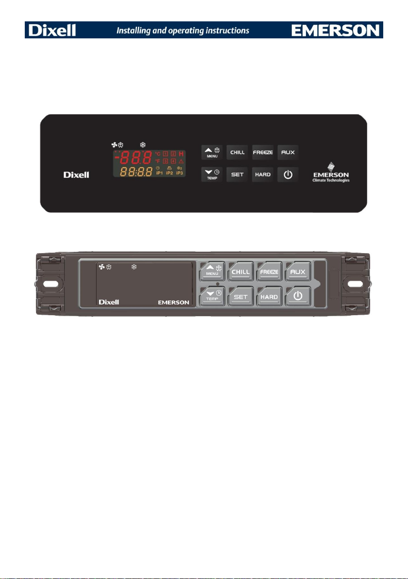
XB590L
BLAST CHILLER

1592006230 XB590L GB r1.0 29.02.2016 XB590L 2/32
INDEX
1. GENERAL WARNING 4
1.1 PLEASE READ BEFORE USING THIS MANUAL ......................................................................................... 4
1.2 SAFETY PRECAUTIONS ............................................................................................................................... 4
2. GENERAL FEATURES 4
3. MOUNTING & INSTALLATION 5
3.1 CUT OUT FOR FRONT OR BACK-PANEL MOUNTING............................................................................... 5
4. CONNECTIONS 5
5. FRONT PANEL 6
5.1 POLYCARBONATE VERSION (BACK PANEL MOUNTING - STANDARD DIXELL) ................................... 6
5.2 INOX VERSION (FRONT PANEL MOUNTING – STANDARD DIXELL) ....................................................... 6
6. QUICK REFERENCE GUIDE 6
6.1 DISPLAY ......................................................................................................................................................... 6
6.2 KEYBOARD .................................................................................................................................................... 6
6.3 INSTRUMENT IN OFF AND STAND-BY ....................................................................................................... 7
6.4 STARTING A CYCLE ..................................................................................................................................... 7
6.5 THE KEYBOARD AND DISPLAY DURING OPERATION OF A CYCLE ...................................................... 8
6.6 OTHER FUNCTIONS (DEPENDING ON THE CONFIGURATION OF THE KEYS) ..................................... 9
6.7 KEY COMBINATIONS .................................................................................................................................... 9
6.8 CONFIGURATION OF KEYS ....................................................................................................................... 10
6.9 MEANING OF THE LEDS............................................................................................................................. 10
7. CHILLING CYCLES (1, 2, 3, 4) 11
7.1 HOW TO EDIT THE PARAMETERS OF A CHILLING/FREEZING CYCLE ................................................ 11
7.2 STRUCTURE OF CHILLING/FREEZING CYCLES (1,2,3,4) - PARAMETERS .......................................... 12
7.3 INSERT PROBE MANAGEMENT ................................................................................................................ 13
7.4 CHILLING CYCLE EXAMPLE ...................................................................................................................... 14
7.4.1 First phase: “Hard chill” ................................................................................................................................................... 14
7.4.2 Second phase: “Soft chill” ............................................................................................................................................... 14
7.4.3 Third phase: “Freezing cycle” ......................................................................................................................................... 14
7.4.4 End of the freezing cycle and start of the hold phase (selectable) .................................................................................. 15
8. DEFROST 15
8.1 DEFROST REQUEST .................................................................................................................................. 15
8.1.1 Expiration of interval between defrosts (only during hold) ............................................................................................... 15
8.1.2 Pressing of DEF key (only during hold) ........................................................................................................................... 15
8.2 TYPE OF DEFROST .................................................................................................................................... 15
8.2.1 With electric heater (tdF=rE) ........................................................................................................................................... 15
8.2.2 With Hot Gas (tdF=in) ..................................................................................................................................................... 16
8.3 END OF DEFROST ...................................................................................................................................... 16
8.3.1 Timed .............................................................................................................................................................................. 16
8.3.2 Because of temperature .................................................................................................................................................. 16
8.3.3 Request for defrost with evaporator probe temperature greater than the end-of-defrost temperature dtE. ..................... 16
8.4 DRAIN TIME ................................................................................................................................................. 16
8.5 TEMPERATURE ALARM DELAY AFTER DEFROST ................................................................................. 16
8.6 DISPLAY DURING DEFROST ..................................................................................................................... 16
9. CLOCK MANAGEMENT 17
10. CONDENSER TEMPERATURE ALARM MANAGEMENT 17
11. ALARM SIGNALS 17
11.1 KIND OF ALARMS ........................................................................................................................................ 17
11.2 HACCP ALARMS .......................................................................................................................................... 18
12. COMPRESSOR CRANKCASE HEATING DELAY 19
13. PROGRAMMING PARAMETERS 20
13.1 USER PARAMETERS PR1 LEVEL .............................................................................................................. 20
13.1.1 How to access programming .......................................................................................................................................... 20
13.2 PARAMETERS WITH PR2 LEVEL PASSWORD ........................................................................................ 20
14. PARAMETERS 21
14.1 PROBE .......................................................................................................................................................... 21
14.2 DISPLAY AND MEASUREMENT UNIT ....................................................................................................... 21
14.3 DIGITAL INPUTS .......................................................................................................................................... 21
14.4 AUXILIARY RELAY CONFIGURATION ....................................................................................................... 22
14.5 SECOND RELAY MANAGEMENT ............................................................................................................... 22
14.6 AUXILIARY RELAY MANAGEMENT ........................................................................................................... 22
14.7 DEFROST ..................................................................................................................................................... 22

1592006230 XB590L GB r1.0 29.02.2016 XB590L 3/32
14.8 FANS ............................................................................................................................................................. 22
14.9 TEMPERATURE ALARMS ........................................................................................................................... 23
14.10 CONDENSER TEMPERATURE ALARM ............................................................................................... 23
14.11 CONFIGURATION OF KEYS ................................................................................................................. 23
14.12 CARTER HEATING ................................................................................................................................ 23
14.13 CYCLE ACTIVATED BY 2° DIGITAL INPUT ......................................................................................... 23
14.14 CYCLE LOG ........................................................................................................................................... 23
14.15 OTHER ................................................................................................................................................... 24
15. PRINTER MANAGEMENT (IF PROVIDED AND CONFIGURED) 24
15.1 XB07PR – KIT (OPTIONAL) ........................................................................................................................ 24
15.2 XB07PR - DIMENSIONS .............................................................................................................................. 24
15.3 XB07PR – MOUNTING ................................................................................................................................. 25
15.4 CONNECTION TO THE XB590L – XB07PR ................................................................................................ 25
15.5 PRINTER SETTING ...................................................................................................................................... 26
16. ELECTRICAL CONNECTIONS 26
16.1 PROBES CONNECTION .............................................................................................................................. 26
17. SERIAL LINE 27
18. USE OF THE PROGRAMMING “HOT KEY “ 27
18.1 DOWNLOAD (FROM THE “HOT KEY” TO THE INSTRUMENT) ................................................................ 27
18.2 DOWNLOAD PROCEDURE OF PARAMETERS FROM THE INSTRUMENT TO THE USB KEY ............ 27
19. TECHNICAL DATA 28
20. STANDARD VALUES OF THE PARAMETERS. 29
20.1 Chilling cycles ............................................................................................................................................... 31

1592006230 XB590L GB r1.0 29.02.2016 XB590L 4/32
1. GENERAL WARNING
1.1 PLEASE READ BEFORE USING THIS MANUAL
This manual is part of the product and should be kept near the instrument for easy and quick reference.
The instrument shall not be used for purposes different from those described hereunder. It cannot be used
as a safety device.
Check the application limits before proceeding.
Dixell Srl reserves the right to change the composition of its products, even without notice, ensuring the
same and unchanged functionality.
1.2 SAFETY PRECAUTIONS
Check the supply voltage is correct before connecting the instrument.
Do not expose to water or moisture: use the controller only within the operating limits avoiding sudden
temperature changes with high atmospheric humidity to prevent formation of condensation
Warning: disconnect all electrical connections before any kind of maintenance.
Fit the probe where it is not accessible by the End User. The instrument must not be opened.
In case of failure or faulty operation send the instrument back to the distributor or to “Dixell S.r.l.” (see
address) with a detailed description of the fault.
Consider the maximum current which can be applied to each relay (see Technical Data).
Ensure that the wires for probes, loads and the power supply are separated and far enough from each
other, without crossing or intertwining.
In case of applications in industrial environments, the use of mains filters (our mod. FT1) in parallel with
inductive loads could be useful.
2. GENERAL FEATURES
The series XB has been created for fast chilling or freezing goods according to international food safety
standards. Lo strumento dispone delle seguenti funzioni:
there are FOUR types of cycles:
* Soft Chilling
* Hard Chilling
* Soft Freezing
* Hard Freezing
At the end of each cycle the instrument switches automatically to Hold mode.
The user can select one of them according to his own requirements and modify it as he wants..
Any cycle can be manually terminated before the normal.
Each cycle can use up to 3 insert probes or a MultiPoint probe (max 3 points) to be inserted in the product.
During the Cycle there are no defrosts and the fans are always on, a defrost cycle can be done before any
freezing cycle.
Each cycle can be divided into 3 phases + hold with dedicated parameters.
Low and high temperature alarm management of the condenser.
Log of last 15 HACCP alarm incidents (high temperature, power failure and maximum cycle time
exceeded).
Option to activate a delay on instrument startup to enable heating of the compressor carter.
Each instrument is provided with an output for remote display
The XB590L controller is provided with internal real time clock and can be connected to the XB07PR
printer.
Reading and writing parameters can be managed, in addition from the instrument keyboard, through the
Dixell Wizmate software.
1592006230 XB590L GB r1.0 29.02.2016 XB590L 5/32
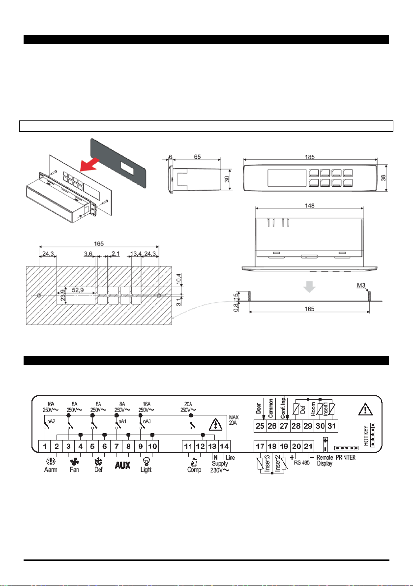
3. MOUNTING & INSTALLATION
The XB590L can be fitted to the back panel, with a 150x31mm hole, and fixed with 2 studs 165mm apart. To
increase protection, use the rear-front protective rubber mod. PG-L (optional). To apply the polycarbonate in
the front panel, drill a hole in the panel as shown in chapter 3.1.
The ambient operating temperature range is from 0÷60°C (RH 20÷85%). Avoid locations subject to heavy
vibration, corrosive gases or excessive dirt. The same warnings have to be applied to the probes. Ensure
enought ventilation around the instrument.
3.1 CUT OUT FOR FRONT OR BACK-PANEL MOUNTING
4. CONNECTIONS
Insert probes 2 and 3 (17-18-19) are disabled at the factory.
Relay outputs 9-10 (oA3)=light, 7-8 (oA1)=Aux, 1-2(oA2)=alarm are configured at the factory.
Port micro connects to contacts 25-26.
1592006230 XB590L GB r1.0 29.02.2016 XB590L 6/32
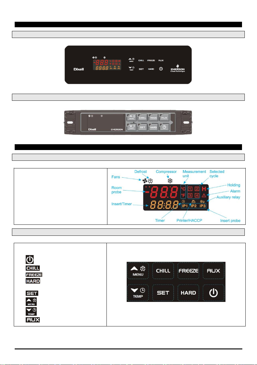
5. FRONT PANEL
5.1 POLYCARBONATE VERSION (BACK PANEL MOUNTING - STANDARD DIXELL)
5.2 INOX VERSION (FRONT PANEL MOUNTING – STANDARD DIXELL)
6. QUICK REFERENCE GUIDE
6.1 DISPLAY
Upper Display: Cell temperature
Lower Display:Timer or insert probe
Alarm and status icons.
If an icon or LED is on, the correspondent
function is enabled.
If an icon or LED is flashing, the
correspondent function is delayed.
6.2 KEYBOARD
The keyboard consists of 8 keys
configured as follows:
On/Off
Chilling cycle
Freezing cycle
Hard Cycles (Chilling and
freezing)
Setting holding set
Menu key, up and defrosting
Down key, temperature/time
Auxiliary exit key
1592006230 XB590L GB r1.0 29.02.2016 XB590L 7/32
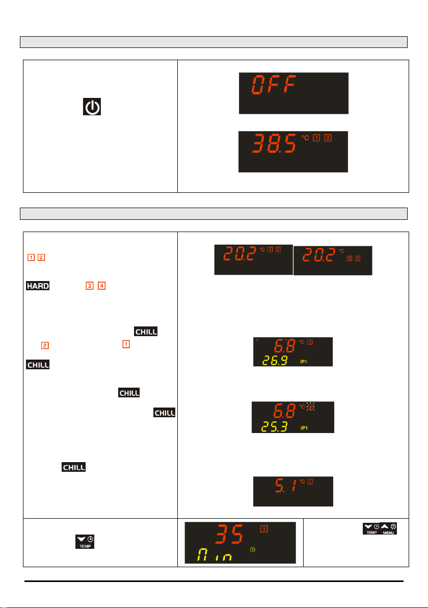
6.3 INSTRUMENT IN OFF AND STAND-BY
Off:
To switch on the instrument from the OFF
status, shown by the OFF label on the
display.
press the button .
The instrument will be placed in stand-by
while waiting for a cycle to be selected and
displaying the temperature of the control
probe.
Display in the OFF status:
Display in the Stand-by status:
6.4 STARTING A CYCLE
Stand-by:
On switching the instrument on, the icons
in the display will flash to indicate
that the Soft Chilling (1) or Soft Freezing (2)
cycles can be selected; by pressing the key
the LEDs will flash to indicate
that the Hard Chilling (3) or Hard Freezing
(4) cycles can be selected.
Soft Chilling selection:
Press and release the button , the
icon turns off and the icon stays on. To
start the cycle press and release the key
.
Manual interruption:
Press and release the key . The icon
for the current cycle starts to flash. The
cycle is restarted by pressing the key
again or automatically after the time set by
the PAU parameter (maximum time cycle
interruption).
Final stop:
Keep the button pressed for more
than 2 seconds; the controller will go into
stand-by.
Stand-by SOFT Cycles Stand-by HARD Cycles
SOFT Chilling on
Manual interruption (cycle icon which flashes)
Final stop of cycle
Setting the clock(RTC):
Keep the key pressed to access the
clock menu and set the date and time.
Use the arrows
to view the elements:
Min= minutes
Hou= hour

1592006230 XB590L GB r1.0 29.02.2016 XB590L 8/32
Use the arrows to move
between the parameters.
- To edit: press and set the desired
value with the arrows.
- To confirm: press .
- To exit from the menu: press the keys
together or wait 5 sec.
dAY= day
Mon= month
YEA= year
tiM=date format
Eu=dd/mm/yyyy
USA =mm/dd/yyyy
Set the holding temperature at cycle
end:
If a chilling cycle requires holding then
press and release the key , and its
HdS value (holding setpoint) will be
displayed for 5 seconds.
To edit HdS:
within 5 seconds keep pressed until
HdS flashes, use the arrows to
edit the value.
To confirm:
press the key again.
To disable the holding:
To disable the holding simply set the
parameter HdS=OFF; this value can be set
as 50.1°C)
Example of a holding
setpoint which will start at the
end of the Soft Chilling cycle.
After a Chilling or Freezing
cycle, the device switches to
hold; this phase is
recognised because the icon
is on.
6.5 THE KEYBOARD AND DISPLAY DURING OPERATION OF A CYCLE
After starting a chilling cycle, the display will show the following information:
Temperature displaying:
Upper display: thermostat probe.
Lower display: insert probe (if enabled) or
the countdown of the maximum time.
Displaying change:
by pressing the button the probes iP2,
iP3 (if present) are displayed in sequence
and followed by the maximum duration to
the end of the cycle.
Thermostat probe temperature
Insert probe temperature
Thermostat probe temperature
Remaining time
Displaying cycle phase:
By pressing once, the phase of the
current cycle is displayed for 5 seconds. If a
phase is not enabled this will not be
displayed.
Depending on the cycle
configuration, the display will
show:
PH1= phase 1
PH2= phase 2
PH3= phase 3
1592006230 XB590L GB r1.0 29.02.2016 XB590L 9/32
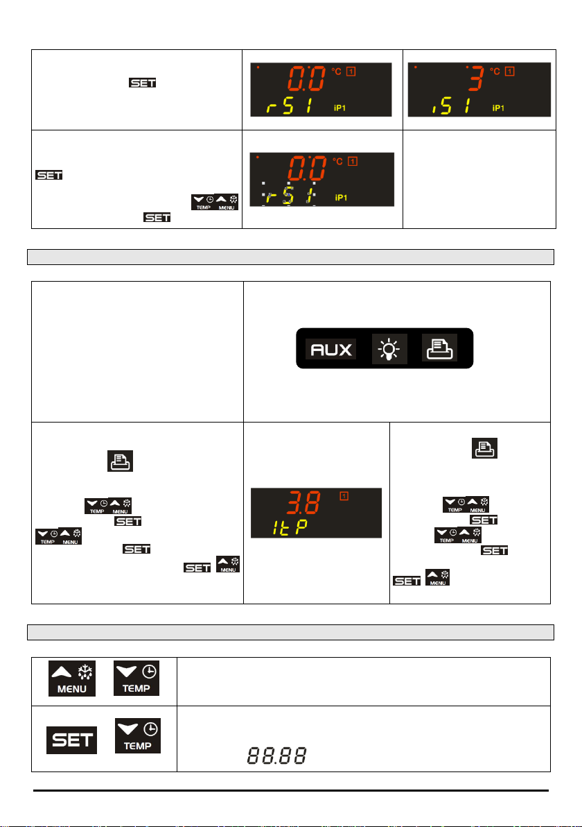
Checking the control set:
By pressing the key in sequence:
1) rSI = thermostat set
2) iSI = phase end set for the probe
3) return to normal display
Changing the control sets:
When rSI or iSI are displayed, hold the key
pressed until the label on the display
flashes.
At this point, use the arrow keys
and then press the key to confirm.
6.6 OTHER FUNCTIONS (DEPENDING ON THE CONFIGURATION OF THE KEYS)
AUX: by pressing and releasing the AUX
key you activate/deactivate the auxiliary
relay (if configured)
LIGHT: Pressing and releasing it activates
or deactivates the light relay.
PRINTER: by pressing the key, if it is
connected to a printer, printing starts at
intervals as per the configuration.
PRINTER CONFIGURATION
Press the key for a few seconds to
access the printer menu.
The first label itP is displayed.
To scroll:
To edit: press and then the keys
To confirm: press .
To exit from the menu: press +
together or wait 5 seconds.
PRINTER CONFIGURATION
Press the key for a few
seconds to access the printer
menu.
The first label itP is displayed.
To scroll:
To edit: press and then
the keys
To confirm: press .
To exit from the menu: press
+ together or wait 5
seconds.
6.7 KEY COMBINATIONS
+
The keyboard unlock or lock combination; the lock does not allow editing the
parameters while the instrument functions are still active.
+
Access to parameter programming from stand-by.
From level "Pr2" you can show or hide a parameter in level "Pr1"; from level
Pr2 it is clear whether the parameter is visible in Pr1 if the point of the lower
display is on
1592006230 XB590L GB r1.0 29.02.2016 XB590L 10/32
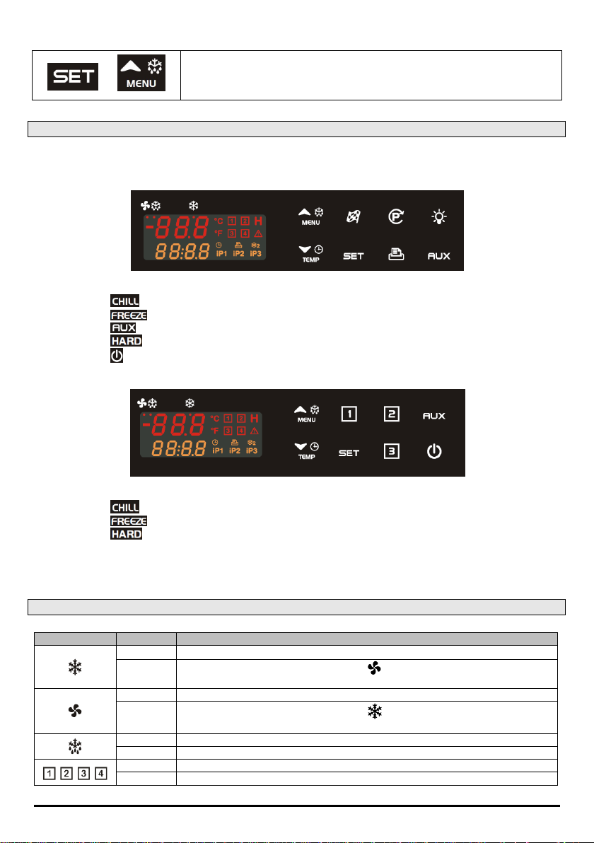
+
From programming, you go back to the upper menu
6.8 CONFIGURATION OF KEYS
The instrument, compared to the standard Dixell configuration, can be configured with different functions for
the keys; other possible configurations are:
This type of configuration requires:
Key (parameter b2) configured as SSt
Key (parameter b3) configured as SCy
Key (parameter b4) configured as Lig
Key (parameter b7) configured as Prn
Key (parameter b8) configured as AuS.
This type of configuration requires:
Key (parameter b2) configured as Cy1
Key (parameter b3) configured as Cy2
Key (parameter b7) configured as Cy3
If the keys are configured with the same function, the controller display will display the label “Err ConF”.
6.9 MEANING OF THE LEDS
LED
MODE
ACTION
ON
Compressor enabled
Flashing
Programming Phase (flashing with LED )
Anti-short cycle delay enabled
ON
Fan enabled
Flashing
Programming Phase (flashing with LED )
Activation delay active
ON
Defrost active
Flashing
Drip time active
ON
Freezing cycle 1, 2, 3, 4 or hold mode active
Flashing
Cycle not yet selected or cycle temporarily suspended
 Loading...