

Page 1

Dixell
Installing and Operating Instructions
release 7.0
XR160C - XR160D - XR170C - XR170D - XR162C - XR172C
CONTENTS
1. GENERAL WARNING__________________________________________________ 2
1.1 Please read before using this manual _____________________________________ 2
1.2 Safety Precautions____________________________________________________ 2
2. GENERAL DESCRIPTION ______________________________________________ 2
3. CONTROLLING LOADS________________________________________________ 2
3.1 The compressor______________________________________________________ 2
3.2 Fast freezing ________________________________________________________ 3
3.3 Defrost _____________________________________________________________ 3
3.4 “Air dryer” applications_________________________________________________ 3
3.5 Control of evaporator fans ______________________________________________ 3
3.6 Fan relay used as 2° compressor ________________________________________ 3
4. FRONT PANEL COMMANDS____________________________________________ 3
4.1 Use of LEDS ________________________________________________________ 4
5. FUNCTION AND PARAMETERS’ PROGRAMMING MENU ____________________ 4
5.1 Function Menu_______________________________________________________ 4
5.2 List of functions ______________________________________________________ 4
5.3 Exit Timeout_________________________________________________________ 5
5.4 Accessing “Pr2” and SECURITY CODE input _______________________________ 5
5.5 Changing a parameter’s value___________________________________________ 5
6. LIST OF PARAMETERS________________________________________________ 5
7. INSTALLATION AND MOUNTING ________________________________________ 7
8. ELECTRICAL CONNECTIONS __________________________________________ 7
8.1 Probes connection____________________________________________________ 7
9. ALARM SIGNALS_____________________________________________________ 7
9.1 Silencing buzzer / alarm relay output______________________________________ 7
9.2 Alarm “EE” __________________________________________________________ 7
9.3 Alarm reset through keyboard ___________________________________________ 8
9.4 Alarm recovery_______________________________________________________ 8
10. TECHNICAL DATA ___________________________________________________ 8
11. CONNECTIONS _____________________________________________________ 9
12. DEFAULT SETTING VALUES
952057-58 XR160C - XR170C - XR160D - XR170D - XR162C - XR172C 1/י
- STANDARD MODELS _____________________ 10
Page 2
Dixell
Installing and Operating Instructions
release 7.0
1. GENERAL WARNING
1.1 Please read before using this manual
• This manual is part of the product and should be kept near the instrument for easy and quick reference.
• The instrument shall not be used for purposes different from those described hereunder. It cannot be used
as a safety device.
• Check the application limits before proceeding.
1.2
• Check the supply voltage is correct before connecting the instrument.
• Do not expose to water or moisture: use the controller only within the operating limits avoiding sudden
temperature changes with high atmospheric humidity to prevent formation of condensation
• Warning: disconnect all electrical connections before any kind of maintenance.
• The instrument must not be opened.
• Fit the probe where it is not accessible by the End User.
• In case of failure or faulty operation send the instrument back to the distributor or to dIXEL s.r.l (see
address) with a detailed description of the fault.
• Consider the maximum current which can be applied to each relay (see Technical Data).
• Ensure that the wires for probes, loads and the power supply are separated and far enough from each
other, without crossing or intertwining.
• In case of applications in industrial environments, the use of mains filters (our mod. FT1) in parallel with
inductive loads could be useful.
Safety Precautions
2. GENERAL DESCRIPTION
Models XR160C and XR170C, 32x74 mm format, are microprocessor based controllers suitable for
applications on medium or low temperature refrigerating units. They are provided with three relay outputs to
control compressor, defrost - which can be either electrical or hot gas - and the evaporator fans. They are also
provided with two PTC probe inputs, one for temperature control, the other to be located onto the evaporator
to control the defrost termination temperature.
Model XR170C also features an additional relay for the alarm output and an internal buzzer for acoustic signal.
Models XR160D and XR170D, DIN RAIL format, provide the same features as the correspondent XR160C
and XR170C models. Alarm conditions in model XR160D are also signalled by a 12V/40mA output.
Models XR162C and XR172C, matched with slave devices XR30SL and XR40SL respectively, provide the
same features as XR160C and XR170C.
Each instrument is fully configurable through special parameters that can be easily programmed through the
keypad.
3. CONTROLLING LOADS
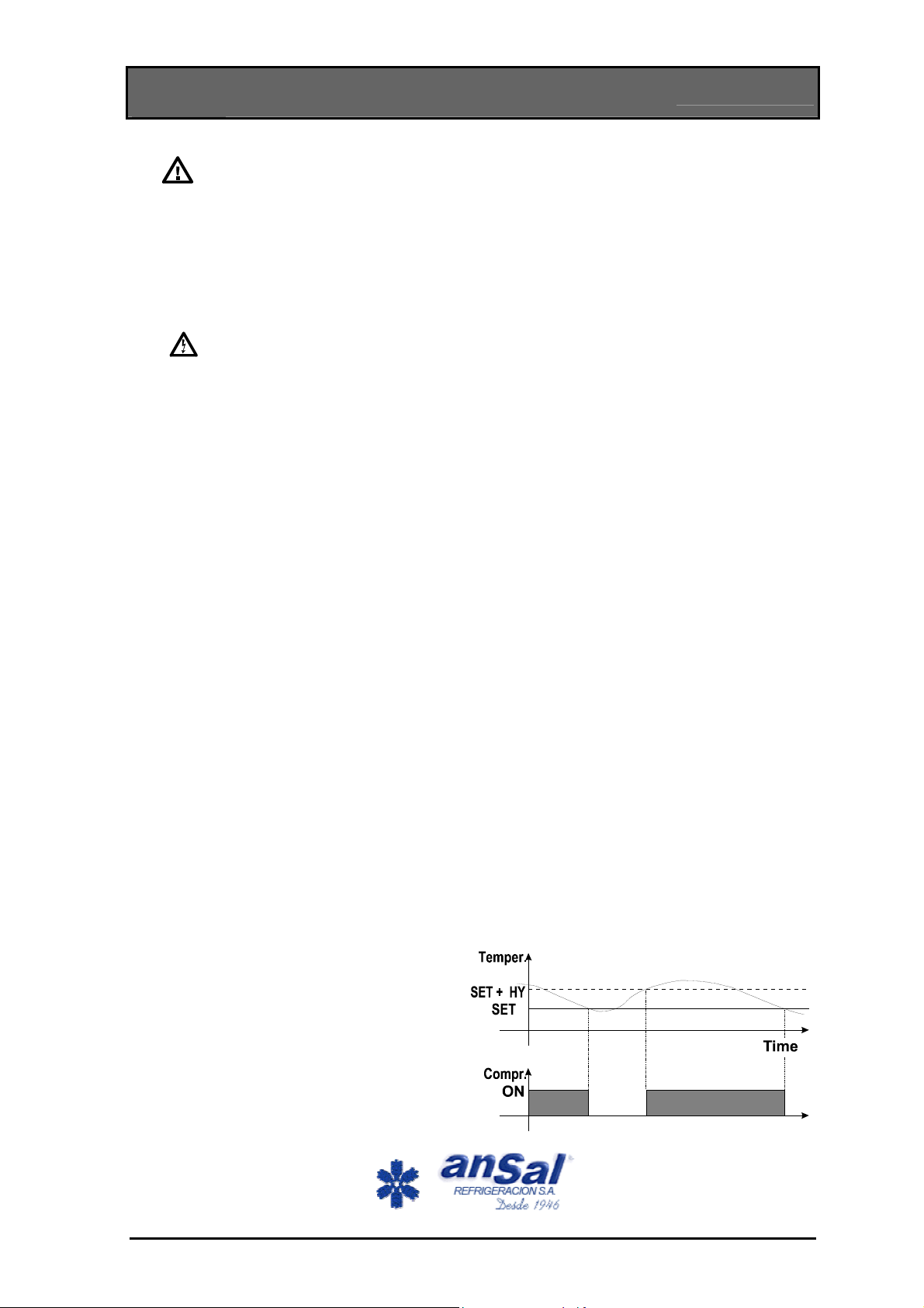
3.1 The compressor
The regulation is performed according to the
temperature measured by the thermostat probe
with a positive differential from the set point: if the
temperature increases and reaches set point plus
differential the compressor is started and then
turned off when the temperature reaches the set
point value again.
In case of fault in the thermostat probe the start
and stop of the compressor are timed through
parameters “COn” and “COF”.
952057-58 XR160C - XR170C - XR160D - XR170D - XR162C - XR172C 2/י
Page 3
Dixell
Installing and Operating Instructions
release 7.0
3.2 Fast freezing
When defrost is not in progress, it can be activated the keypad by holding the “UP” key pressed for about 3
seconds. The compressor operates in continuous mode for the time set through the “CCt” parameter. The
cycle can be terminated before the end of the set time using the same activation key, “UP” for about 3
seconds.
3.3 Defrost
Two defrost modes are available through the “tdF” parameter: defrost through electrical heater (tdF = 0) and
hot gas defrost (tdF = 1). Other parameters are used to control the interval between defrost cycles and its
maximum length.The defrost end is controlled by the evaporator’s probe.
At the end of defrost the drip time starts - it is controlled through the “Fdt” parameter.
3.4 “Air dryer” applications
The tdF parameter can be set also for “Air dryer” applications. In this case (tdF=2 or 3) the defrost relay is
energised according to the “Short Time” mode. The following parameter table describes the cycle times when
the tdF parameter is selected for Long or Short time.
Parameters Long time (tdF = 0; 1) Short time (tdF = 2; 3)
dAF, dSd, MdF, Fdt minutes seconds
IdF hours minutes
3.5 Control of evaporator fans
The fan control mode is selected by means of the “FnC” parameter:
FnC=0 fans will switch ON and OFF with the compressor and not run during defrost:;
FnC=1 fans will run continuously, but not during defrost
After defrost, there is a timed fan delay allowing for drip time, set by means of the “Fnd” parameter.
FnC=2 fans will switch ON and OFF with the compressor and run during defrost;
FnC=3 fans will run continuously also during defrost
An additional parameter “FSt” provides the setting of temperature, detected by the evaporator probe, above
which the fans are always OFF. This can be used to make sure circulation of air only if his temperature is
lower than set in “FSt”.
3.6 Fan relay used as 2° compressor
If FnC=4 the fan relay is programmed to control a second compressor, in this case the Fnd parameter value is
defined as time delay, in seconds, between turning on compressors 1 and 2.
4. FRONT PANEL COMMANDS
SET: TO DISPLAY TARGET SET POINT: by pressing and releasing this key the set point is displayed
for 5s.
TO MODIFY SET POINT: by holding the key pressed for at least 2s set point change mode is entered: the set
point is displayed and the LEDs of the first and third digits blink. To change the value use the “UP”
and “DOWN” keys. The new value can be stored either by pressing the “SET” key (the instrument
TO START A FAST FREEZING CYCLE: in normal operation, by holding it pressed for 3s the fast
restores temperature display) or by waiting the exit time-out to expire (15s).
(UP): in programming mode or in “Function Menu” it browses the parameter codes or increases the
value of the displayed variable. Hold pressed for a faster change.
freezing cycle is started. Such cycle can be interrupted by holding the “UP” key pressed for 3s.
952057-58 XR160C - XR170C - XR160D - XR170D - XR162C - XR172C 3/י
Page 4

Dixell
(DOWN): in programming mode or in “Function Menu” it browses the parameter codes or decreases
the value of the displayed variable. Hold pressed for a faster change.
TO START A MANUAL DEFROST: by holding it pressed for 3s the defrost cycle is started
KEY COMBINATIONS:
Installing and Operating Instructions
release 7.0
+ TO UNLOCK THE KEYBOARD: when held pressed for 3s the keyboard is unlocked (see
“LOC” function).
SET +
TO ENTER ON FUNCTION MENU: when held pressed for 3s the Function Menu is entered.
SET +
TO RETURN TO THE ROOM TEMPERATURE DISPLAY: programming end, return to the
room temperature display.
4.1 Use of LEDS
A series of light points on the front panels is used to monitor the loads
controlled by the instrument. Each LED function is described in the
following table.
LED MODE Function
Alarm
ON Compressor enabled
FLASHING
ON Fan enabled
FLASHING
ON Defrost enabled
FLASHING Drip time in progress
ON Fast freezing enabled
ON - ALARM signal
- Programming Phase (flashing with LED )
- Anti-short cycle delay enabled
Programming Phase (flashing with LED )
- In “Pr2” indicates the parameter is also present in “Pr1”
5. FUNCTION AND PARAMETERS’ PROGRAMMING MENU
5.1 Function Menu
Includes all the main functions controlled by the instrument.
Access procedure:
• The menu is entered by holding the SET and DOWN keys pressed for three seconds. The label of the first
function is displayed.
• The UP and DOWN keys are used to cycle backwards or forward in the menu.
• By pressing the SET key the currently displayed function is enabled.
5.2 List of functions
1. “dFt”: displays for 5s the time to defrost [hours].
2. “Pt2”: displays for 5s the temperature of the second probe.
3. “Pr1”: includes all user accessible parameters.
952057-58 XR160C - XR170C - XR160D - XR170D - XR162C - XR172C 4/י
Page 5

Dixell
4. “Pr2”: includes all the instrument’s parameters (at installer level). It can be accessed through a security
code. Hence it is possible to modify all parameters and add or remove parameters from “Pr1” (user level)
by pressing “SET” + “DOWN”. When a parameter is enabled at user level, LED (Alarm LED) is on.
5. “LOC”: keyboard lock. When enabled the “POF” flashing message is displayed for a few seconds then the
keys are locked . Only the set point display is enabled.
6. “Out”: exits from menu.
From functions “dFt” and “Pt2” the instrument will go back to “Functions Menu” by time out. From the all other
functions the instrument will display again the room temperature by time out.
Installing and Operating Instructions
release 7.0
5.3 Exit Timeout
If no key is pressed within 15 seconds the instrument switches back to room temperature display mode.
5.4 Accessing “Pr2” and SECURITY CODE input
To access parameters in “Pr2” a security code is required.
1. Enter Function Menu, select label “Pr2” and press the “SET” key. The “PAS” flashing message is
displayed, shortly followed by “0 - -” with a flashing zero.
2. Use “UP” or “DOWN” to input the security code in the flashing digit;
3. Confirm the figure by pressing “SET”.
4. Repeat operations 2 and 3 for the other digits.
5. If the security code is correct the access to “Pr2” is enabled by pressing “SET” on the last digit, otherwise
the security code input process restarts from the beginning.
If no key is pressed within 15 seconds the instrument reverts to room temperature display mode.
SECURITY CODE is 321
NOTE: each parameter in “Pr2” can be removed or put into “Pr1” (user level) by pressing “SET” + “DOWN”.
When a parameter is present in “Pr1” LED
is on.
5.5 Changing a parameter’s value
Each parameter is identified by a special alphanumeric code (label).
To change the parameter’s value operate as follows:
1. Enter the Function Menu and select the parameters’ list you require: “Pr1” or “Pr2”.
2. Browse the parameters’ list using “UP” or “DOWN” until the required parameter is displayed.
3. Press the “SET” key to display its value.
4. Use “UP” or “DOWN” to change its value.
5. Press “SET” to store the new value and skip to the following parameter.
TO EXIT: Press “SET”+”UP” or wait 15s without pressing a key.
NOTE: the set value is stored even when the procedure is exited by waiting the timeout to expire.
6. LIST OF PARAMETERS
Hy Differential: (0,2°C ÷ 12,0°C / 2°F ÷120°F) Intervention differential for set point, always positive.
Compressor Cut IN is Set Point Plus Differential (Hy). Compressor Cut OUT is when the temperature
reaches the set point.
LS Minimum set point: (-57°C÷SET/-57°F÷SET): Sets the minimum acceptable value for the set point.
US Maximum set point: (SET÷99°C/SET÷196°F). Set the maximum acceptable value for set point.
AC Anti-short cycle delay: (0÷30 min) minimum interval between the compressor stop and the following
restart.
ALC Temperature alarms configuration: (0 = temperature alarm are related to SET, alarm relay and buzzer
works in parallel; 1 = temperature alarms are referred to absolute values; alarm relay and buzzer work in
parallel; 2= referred to set, alarm relay is active when the alarm is active; 3= absolute temperature, alarm
relay is active when the alarm is active) determines if temperature alarms are referred to set point or if
alarms are referred to absolute temperatures.
952057-58 XR160C - XR170C - XR160D - XR170D - XR162C - XR172C 5/י
Page 6

Dixell
ALU MAXIMUM temperature alarm: (with ALC = 0 or 2, from 0 to 50°C/90°F; with ALC = 1 o 3, from
ALL÷99°C/196°F) when this temperature is reached the alarm is enabled, after the ALd delay time.
ALL Minimum temperature alarm: (with ALC = 0 or 2, from 0 to 50°C/90°F; with ALC = 1 or 3, from -
57°C/°F to ALU) when this temperature is reached the alarm is enabled, after the ALd delay time.
ALd Temperature alarm delay: (0÷120 min) time interval between the detection of an alarm condition and
alarm signalling.
dAO Delay of temperature alarm at startup: (from 0 min to 720 min; res. 10min) time interval between the
detection of the temperature alarm condition after instrument power on and alarm signalling.
OdS Outputs activation delay at start up: (0÷120min) This function is enabled at the initial start up of the
instrument and inhibits any output activation for the period of time set in the parameter.
CCt Compressor ON time during fast freezing: (0÷990min; res. 10 min) allows to set the length of the
continuous cycle. Can be used, for instance, when the room is filled with new products.
dAF Defrost delay after fast freezing: (with tdF=0 or 1: 0÷120min; with tdF=2 or 3: 0÷120sec) time interval
between the end of the fast freezing and the following defrost related to it.
IdF Interval between defrost cycles: (with tdF=0 or 1: 0÷120h; with tdF=2 or 3: 0÷120min) Determines the
time interval between the beginning of two defrost cycles.
dSd Start defrost delay:(with tdF=0 or 1: 0÷59min; with tdF=2 or 3: 0÷59sec) This is useful when different
defrost start times are necessary to avoid overloading the plant.
MdF (Maximum) length for defrost:(with tdF=0 or 1: 0÷120min; with tdF=2 or 3: 0÷120sec) When EdF = 0,
(not evaporator probe: timed defrost) it sets the defrost duration, when EdF = 1 (defrost end based on
temperature) it sets the maximum length for defrost.
dtE Defrost termination temperature: (-57 ÷ 99°C/-57÷196°F) (Enabled only when EdF=1) sets the
temperature measured by the evaporator probe, which causes the end of defrost.
dFd Temperature displayed during defrost: (0 = real temperature; 1 = temperature at defrost start; 2 = set
point; 3 = “dEF” label)
dAd MAX display delay after defrost: (0÷120 min). Sets the maximum time between the end of defrost and
the restarting of the real room temperature display.
tdF Defrost type: (0 = electrical heater, long time; 1 = hot gas, long time; 2=OFF compressor, short
time; 3= ON compressor, short time)
EdF Evaporator probe presence: (0 = Not present: timed defrost end; 1=present: defrost end based on
temperature)
Fdt Drain time: (with tdF=0 or 1: 0÷120min; with tdF=2 or 3: 0÷120sec) time interval between reaching
defrost termination temperature and the restoring of the control’s normal operation. This time allows the
evaporator to eliminate water drops that might have formed due to defrost.
dPO First defrost after startup: (0 = Immediately; 1 = after the IdF time)
FnC Fan operating mode: (0 = runs with the compressor, OFF during defrost; 1 = continuous mode, OFF
during defrost; 2 = runs with the compressor, ON during defrost; 3 = continuous mode, ON during
defrost; 4 = fan relay is used as 2° compressor output)
FSt Fan stop temperature: (-57÷99°C/196°F) setting of temperature, detected by evaporator probe, above
which the fan is always OFF.
Fnd Fan delay after defrost: (with tdF=0 or 1: 0÷120min; with tdF=2 or 3: 0÷120sec) The time interval
between end of defrost and evaporator fans start.
Ot Thermostat probe calibration: (-12.0÷12.0°C; -120÷120°F) allows to adjust possible offset of the
thermostat probe.
OE Evaporator probe calibration: (-12.0÷12.0°C; -120÷120°F) allows to adjust possible offsets of the
evaporator probe.
CF Temperature measurement unit: 0 = Celsius; 1 = Fahrenheit.
WARNING: When the measurement unit is changed the SET point and the values of the parameters Hy,
LS, US, ALU, ALL, dtE, FSt, Ot and OE have to be modified
COn Compressor ON time with faulty probe (0÷120 min) time during which the compressor is active in case
of faulty thermostat probe. With COn=0 compressor is always OFF.
COF Compressor OFF time with faulty probe (0÷120 min) time during which the compressor is off in case
of faulty thermostat probe. With COF=0 compressor is always active.
Installing and Operating Instructions
release 7.0
952057-58 XR160C - XR170C - XR160D - XR170D - XR162C - XR172C 6/י
Page 7

Dixell
Installing and Operating Instructions
release 7.0
7. INSTALLATION AND MOUNTING
Instruments XR160C, XR170C, XR162C and XR172C shall be mounted on panel, in a 29x71 mm hole, and
fixed using the special bracket supplied. XR160D, XR170D and slave modules XR30SL and XR40SL shall be
mounted on an omega DIN rail. The instruments provided with a slave module shall be connected through the
special multipolar cable supplied.
The temperature range allowed for correct operation is 0 - 60 °C. Avoid places subject to strong vibrations,
corrosive gases, excessive dirt or humidity. The same recommendations apply to probes. Let air circulate by
the cooling holes.
8. ELECTRICAL CONNECTIONS
The instruments are provided with screw terminal block to connect cables with a cross section up to 2,5 mm2.
Before connecting cables make sure the power supply complies with the instrument’s requirements. Separate
the probe cables from the power supply cables, from the outputs and the power connections. Do not exceed
the maximum current allowed on each relay, in case of heavier loads use a suitable external relay.
Instruments XR162C and XR172C are connected to slave modules XR30SL and XR40SL, respectively,
through a multipolar connector (included). They accommodate the instrument relays and the transformer
powering the whole system.
8.1 Probes connection
The probes shall be mounted with the bulb upwards to prevent damages due to casual liquid infiltration. It is
recommended to place the thermostat probe away from air streams to correctly measure the average room
temperature. Place the defrost termination probe among the evaporator fins in the coldest place, where most
ice is formed, far from heaters or from the warmest place during defrost, to prevent premature defrost
termination.
9. ALARM SIGNALS
Message - Mode Cause Outputs
“EE” Flashing Data or memory failure Alarm output ON; Other outputs unchanged
“P1” Flashing Thermostat probe failure Alarm output ON; Compressor output
according to parameters “COn” and “COF”
“P2” Alternating
with room temperature
“HA” Alternating
with room temperature
“LA” Alternating
with room temperature
“dEA” Alternating
with room temperature
“FF” Alternating
with room temperature
9.1 Silencing buzzer / alarm relay output
Once the alarm signal is detected the buzzer and the alarm output can be disabled by pressing any key
according to the ALC par.
With ALC=0 or 1 buzzer and alarm relay are silenced by pressing any key
With ALC=2 or 3 the buzzer is silenced by pressing a key, the alarm relay remains activated as long as the
alarm condition lasts.
The display signal remains as long as the alarm condition remains.
Evaporator probe failure Alarm output ON; Other outputs unchanged;
End defrost is timed
Maximum temperature
alarm
Minimum temperature alarm Alarm output ON; Other outputs unchanged.
Defrost timeout alarm Alarm output ON; Other outputs unchanged.
Fast freezing interrupted by
power failure
Alarm output ON; Other outputs unchanged.
Alarm output ON; Other outputs unchanged.
952057-58 XR160C - XR170C - XR160D - XR170D - XR162C - XR172C 7/י
Page 8

Dixell
Installing and Operating Instructions
release 7.0
9.2 Alarm “EE”
The instruments in the Dixell range are provided with an internal check verifying data and memory integrity.
Alarm “EE” flashes when a failure in data or in the internal memory is detected. In such case the alarm output
is enabled.
WHAT TO DO
1. Cancel the alarm by pressing a key.
2. Check the value of all parameters and restore correct values when wrong.
3. Check the correct instrument operation and in case of further errors replace it.
9.3 Alarm reset through keyboard
It is referred to alarms “EE”, “dEA” and “FF”. Reset is performed by pressing any key while the alarm is being
signalled, then message “rES” is displayed for about 3s before normal operation is restored.
9.4 Alarm recovery
Probe alarms “P1” and “P2” start 30 seconds after the fault in the related probe; they automatically stop 30
seconds after the probe restarts normal operation. Check connections before replacing the probe.
Temperature alarms “HA” and “LA” automatically stop as soon as the thermostat temperature returns to
normal values and when defrost starts.
Alarms “dEA” and “FF” automatically stop after 30 minutes.
10. TECHNICAL DATA
Housing: self extinguishing ABS.
Case
XR160C, XR162C, XR172C: frontal 32x74 mm; depth 60mm;
XR170C: frontal 32x74 mm; depth 70mm
XR160D, XR170D, XR30SL, XR40SL: 4 DIN modules 70x85 mm; depth 61mm.
Mounting
XR160C, XR170C, XR162C, XR172C panel mounting in a 71x29 mm panel cut-out.
XR160D, XR170D, XR30SL, XR40SL: DIN RAIL mounted in a omega (3) din rail .
Frontal protection
XR160C, XR170C, XR162C, XR172C: IP65
Connections: Screw terminal block ≤ 2,5 mm
XR162C is connected to the slave module XR30SL through a multipolar connector.
XR172C is connected to the slave module XR40SL through a multipolar connector.
Power supply
XR160C, XR170C: 12Vac/dc, -10% +15%.
XR160D, XR170D, XR30SL, XR40SL: 110/230Vac, ± 10% 50/60Hz (opt. 24Vac, ± 10% 50/60Hz).
XR162C: by the slave XR30SL.
XR172C: by the slave XR40SL.
Power absorption: 3VA max.
Display: 3 digits, red LED, 14,2 mm high.
Inputs: 2 PTC probes.
Relay outputs
compressor
XR160C, XR170C, XR160D, XR170D: SPDT relay 8(3)A, 250Vac
XR162C, XR172C SPST relay 16(6)A, 250Vac
defrost
XR160C, XR170C, XR162C, XR172C: SPDT relay 8(3) A, 250Vac
XR160D, XR170D: SPST relay 5(2)A, 250Vac
fans
XR160C, XR170C, XR162C, XR172C: SPST 8(3)A, 250Vac
XR160D, XR170D: SPST relay 5(2)A, 250Vac
2
wiring.
952057-58 XR160C - XR170C - XR160D - XR170D - XR162C - XR172C 8/י
Page 9

Dixell
alarm
XR170C, XR172C: SPDT relay 8(3) A, 250Vac
XR170D: SPST relay 5(2)A, 250Vac
Other output
XR160D, XR162C: alarm output 12V/40mA
XR160C, XR170C, XR160D, XR170D, XR172C: buzzer for an acoustic signal of alarms
Data storing: on the non-volatile memory (EEPROM).
Operating temperature: 0÷60 °C.
Relative humidity: 20÷85% (no condensing)
Storage temperature: -30÷85 °C.
Measuring and regulation range: -55÷99 °C / -57÷196 °F
Resolution: 0,1 °C or 1 °F (selectable).
Accuracy of the controller at 25°C: range -40÷50°C (-40÷122°F): ±0,3 °C ±1 digit
Installing and Operating Instructions
11. CONNECTIONS
release 7.0
952057-58 XR160C - XR170C - XR160D - XR170D - XR162C - XR172C 9/י
Page 10

Dixell
Installing and Operating Instructions
release 7.0
12. DEFAULT SETTING VALUES - STANDARD MODELS
PARAMETER
Set LS ÷ US Pr1 -5/0
HY 0,2÷12°C / 2÷120°F Pr1 2/4
LS -57 ÷ Set Pr2 -30/-22
US Set ÷ 99°C / 196°F Pr2 20/68
AC 0 ÷ 30 Pr2 1
ALC 0 o 2=rel (0 ÷50); 1o 3=absolute Pr2 0
ALU 0÷50°C or 90°F /ALL ÷ 99°C / 196°F Pr2 10/20
ALL 0÷50°C or 90°F / -57÷ ALU Pr2 10/20
ALd 0 ÷ 120 Pr2 15
dAO 0 ÷ 720 Pr2 90/180
OdS 0÷120 Pr2 1
CCt 0 ÷ 990 Pr2 240
dAF 0 ÷ 120 Pr2 120
IdF 1 ÷ 120 Pr2 6
dSd 1 ÷ 120 Pr2 0
MdF 0 ÷ 120 Pr2 30
dtE -57 ÷50°C o 196°F Pr2 8/46
dFd 0=Real, 1=Start, 2=Set, 3=dEF Pr2 1
dAd 0 ÷ 120 Pr2 30
tdF 0=Eletrical, 1=Hot gas (Long Time); 2= Relay OFF; 3=Relay ON (Short time) Pr2 0
EdF 0=Not present, 1= Evap. Probe present Pr2 1
Fdt 0 ÷ 120 Pr2 0
dPO 0=Immediately - 1=Normal Pr2 1
FnC OFF during defrost: 0=with compressor; 1=Continuously
ON during defrost: 2=with compressor; 3=Continuously;
FSt -60 ÷ 50°C / 122°F Pr2 2/35
Fnd 0 ÷ 120 Pr2 10
Ot -12÷12°C; -120÷120°F Pr2 0
OE -12÷12°C; -120÷120°F Pr2 0
CF 0=°Celsius 1=°Fahrenheit Pr2 0/1
COn 0 ÷ 120 Pr2 15
COF 0 ÷ 120 Pr2 30
RANGE LEVEL DEFAULT
°C/°F
Pr2 1
4=As 2° compressor
952057-58 XR160C - XR170C - XR160D - XR170D - XR162C - XR172C 10/י
 Loading...