

Page 1

1592030000 xh50_55p r1.2 gb 2011.06.28.doc
XH50-55P 1/5
XH50P - XH55P
Temperature/relative humidity probe with RS485 serial line
1. GENERAL WARNINGS ........... ................. ............... ................ ................ ............. 1
2. DESCRIPTION.. ................ ................ ................ ............... ................. ............... .... 1
3. FIXING, DIM ENSION AND DRILLING ............... ................ ............... ................. ... 1
4. INSTALLATION ADVISE ...... ................. ............... ................ ................ ................ 1
5. WIRING DIAGR AM ... ................. ............... ................ ................ ................ ........... 2
6. DEVICE CONFIGU RATION .............. ................ ................ ................ ............... .... 2
7. CASE CLOSURE ........ ................ ................ ................ ............... ................ .......... 2
8. CASE OPENING ............ ................ ................ ................ ............... ................. ...... 2
9. HOTKEY ............... ................ ................ ................ ............... ................ ................ 3
10. ANTI-SWEAT HEAT ERS REGULATION (WITH RELAY OUTPU T) ... ................ .... 3
11. ANTI-SWEAT HEAT ERS REGULATION (WITH ANALOG OUTPU T) ... ................ . 3
12. CONFIGURATI ON AS THERMOSTAT ............... ................. ............... ................ .. 3
13. KNOB (ONLY XH55P) ......... ................ ................ ................ ............... ................. . 3
14. PARAMETER LIST. ................. ............... ................ ................ ................ .............. 3
15. RELAY CONFIGUR ATION .... ................ ............... ................. ............... ................ 4
16. TECHNICAL D ATA ................ ................ ................ ................ ................ .............. 5
1. GENERAL WARNINGS
1.1 PLEASE READ BEFORE USING THIS MA NUAL
This manual is part of the product and should be kept near t he instrument for easy
and quick reference.
The instrument shall not be used for purposes different from those described
hereunder. It cannot be us ed as a safety device.
Check the application lim its before proceeding.
1.2 SAFET Y PRECAUTIONS
Check the supply voltage is correct before connecting the ins trument.
Do not expose to water or moisture: use the controller only within the operating
limits avoiding s udden t emperature changes with high atmospheric humidity to
prevent formation of condensation
Warning: disconnect all elec trical connections before any kind of m aintenance.
Fit t he probe where it is not accessible by the End User. The instrument must not
be opened.
In case of failure or faulty operation send the inst rument back to the distributor or to
“Dixell S.r.l.” (see address) wit h a detailed description of the fault.
Consider the maximum c urrent which can be applied to each relay (s ee Technical
Data).
Ensure that the wires for probes, loads and the power supply are separated and far
enough from each other, w ithout crossing or intertwining.
In case of applications in industrial environments, the use of m ains filters (our mod.
FT1) in parallel with induct ive loads could be useful.
2. DESCRIPTION
The XH50P and XH55P dev ices (version with knob) are temperature/relative humidity
probe, but their ability to calculate dew-point of the ambient where they are placed,
joined to t he available resources (relay and analog output depending on the models)
make them like a regulators.
Thanks to it s features, the device c an be used a anti-sweat heaters controller on
refrigeration f ield, as a zone therm ostat or as temperature/humidity probe on air
conditioning field. On this m anual, there are some instructions that c an be useful to
configure the device on it s main applications.
3. FIXING, DIMENSION AND DRILLING
During the fixing of the device please, pay attention for the procedure that is described
below.
In order to censure a correct functioning the device has to be placed horizontally (as
indicated by the f igure above) so that the dIXEL logo c an be read, only in this way
the drilling on the case allow the correct inflow of air into the case.
4. INSTALLATION ADVISE
In c ase of XH55P it’s necessary to mount t he knob before
closing the case. First of all, insert the pivot inside of the knob
. The ins ertion of the knob has to be done without effort. The
pivot has a small plastic toot h in order to guide y ou during the
insertion. Ended this operation, insert the other extremity of the
pivot into the trimmer that is mounted on the board as you can
see on the following figure.
Please pay attention during the fixing of the pivot on the trimmer because the small
tooth on the knob has to be on the position described by the f ollowing figure .
In case of box 503 installation, t he cables should be arrive into the devic es through the
central hole as you c an see as follow.
Otherwise, if y ou
need to use wireway
so that you cannot
use the c entral hole,
it’s advised to make
a small hole on the
bottom of t he case
after having
removed the cover
in order to avoid the
possibility to
damage the
electronic board.
Please follow the
figure nearby.
Page 2
1592030000 xh50_55p r1.2 gb 2011.06.28.doc
XH50-55P 2/5
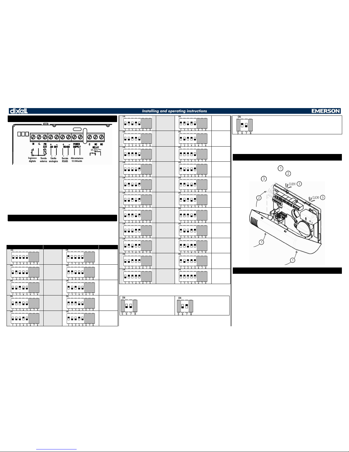
5. WIRING DIAGRAM
Here you can see the full wiring diagram. The presence/ absence of analog output and
the relay size depend on t he.
MEANING OF LEDs
RED LED there is an alarm. It f lashes when an hotkey is detected and during the
copy of the paramet ers with HOTKEY;
GREEN LED It is ON during normal functioning if the device is powered correctly. It
flashes when an hotkey is detected and during the copy of the parameters with
HOTKEY;
YELLOW LED it f lashes quickly if there is serial activ ity and when an hotkey is
detected and during the copy of the parameters with HOTKEY;
6. DEVICE CONFIGURATION
The device can communicate with the serial line only if a serial address is selected. This
setting has to be done with DIP-SWITCH. The s erial address has to be arranged only in
case of using the serial line, if the programming procedure will be made by HOTKEY
this procedure can be skipped. There are 31 address available as ex plained by the
following table:
SELECTOR ADDRESS SELECTOR ADDRESS
ADR 1
ADR 1
ADR 2
ADR 3
ADR 4
ADR 5
ADR 6
ADR 7
ADR 8
ADR 9
ADR 10
ADR 11
ADR 12
ADR 13
ADR 14
ADR 15
ADR 16
ADR 17
ADR 18
ADR 19
ADR 20
ADR 21
ADR 22
ADR 23
ADR 24
ADR 25
ADR 26
ADR 27
ADR 28
ADR 29
ADR 30
ADR 31
With the selectors 6 and 7 it’s possible to configure the internal/external temperature
probe. Please see the follow ing table:
The probe used to
calculate the dew-point is
the internal probe
The probe used to
calculate the dew-point
is the external probe
The device read only t he humidity
Thanks t o the last selector (number 8) it’s possible to select the digital input polarity. If
the selector is in ON position, the digital input is considered as active when the electrical
contact is closed, with t he opposite configuration the digital input is active when the
electrical contact is opened.
7. CASE CLOSURE
After making the connections, please clos e the box following the procedure described
here below. As described as point insert the cover starting from the bottom and
perform a rotat ion as described by point The closing of the case is made when
you’ll hear a light click .
8. CASE OPENING
Please pay at tention in order to av oid the damaging of elect ronic parts. In order to open
the case, you s hould follow the figure below
Page 3

1592030000 xh50_55p r1.2 gb 2011.06.28.doc
XH50-55P 3/5
9. HOTKEY
The configuration of the instrument can be done by serial RS485 line or thanks to the
HOTKEY DK00000100.
HOW TO COPY TH E PARAMETERS FROM DEVICE TO HOTKEY
With d evice powered ON , insert the hotkey in the 5 pin receptacle, the device notices
the hotkey presence and the three LEDs flashes for three sec onds in order to inform you
that the copy is starting. To indicate that the procedure ends up w ith s uccess the
GREEN LED will blink for 5 s econds or otherwise if the procedure ends up without
success the RED LED will blink for 5 seconds, in t his last case it’s necessary to repeat
the procedure or to change t he HOTKEY.
HOW TO COPY TH E PARAMETERS FROM HOTKEY TO DEVICE
With d evice powered OF F, insert the hotkey in the 5 pin receptacle and sw itch on the
device. The procedure starts automatic ally and to indicate that the procedure ends up
with success the GREEN LED will blink for 5 seconds or otherwise if the procedure
ends up without suc cess the RED LED will blink for 5 seconds.
10. ANTI-SWEAT HEATERS REGULATION (WITH RELAY
OUTPUT)
The default factory settings perm it to regulate the anti-sweat heaters with the relay on
board and the external probe that should be placed on the glass. In case of the default
parameters aren’t able to give you the optimum performance, we can advise to change
the following parameters:
ID Descrizione Range Default
odr Regulation offset [-12.0 ÷ 12.0°C] [-21 ÷ 21°F] 1.0°C
Hy Regulation differential [0.1 ÷ 25.5°C] [1 ÷ 45°F] 5.0°C
tAr PWM period 10 ÷ 255 min 10 min
The odr parameter is setted at 1.0°C by default and permits a small safety margin
during the regulation. The Hy parameter perm its t o set the modulation band for the
power of the heaters. R educing Hy the load stays OFF for more time (at the same
temperature and dew-point), increasing Hy we can obtain the opposite functioning. The
relay commutation is performed on the tAr time.
11. ANTI-SWEAT HEATERS REGULATION (WITH ANALOG
OUTPUT)
The regulation of the ant i-sweat heaters t hrough analog output is obtained by changing
AOC paramet er to dEP value. After t hat, it’s poss ible to refine the regulation using odr
and Hy parameters.
12. CONFIGURATION AS THERMOSTAT
By setting rLC=tER the relay works as a simple thermostat based on set point. I n this
case, the device works as zone thermostat in heating mode. By changing the parameter
it’s possible to inv ert the action.
13. KNOB (ONLY XH55P)
In case of XH55P it’s present a knob that permits to set an offset respect to the set
point of 3°C (this value can be changed w ith Ltr and Utr parameters). If the knob is
completely turned off all the output are switched off.
14. PARAMETER LIST
Set Regulation set point: is the set point for relay or analog output regulation.
Hy Regulation differential: band for the regulation of the relay or histeresys of
activation/deactivat ion of relay during thermostatic functioning.
odr Reg ulation offset: offset for regulat ion set point.
HES Energy saving offset: is the energy saving offset that is added to the set point
when the digital input conf igured as i1F=ES is activated.
CH Reg ulation kind of action: direct or reverse functioning for the relay.
rPA Regulation probe A: selects the first regulation probe bet ween: nP=not
present, external probe (Etr) or internal probe (int).
rPb Regulati on probe B: selects the second regulation probe between: nP=not
present, external probe (Etr) or internal probe (int).
rPE Regulation percentage between probes A and B: percentage between probe
A and probe B. The virtual probe follow the formula:
Value = (rPA*rPE + rPb*(100-rPE))/100
CF Measu rement units: °C=Celsius; °F =Fahrenheit. WARNING: after changing
measurement unit you hav e to check all the values of all param eters.
odS Start up outputs delay: allows starting the out put and the regulation wit h soma
delay to allow measurement stabilization.
rHC Digital humidity sensor presence: enable or dis able the humidity sensor.
orH Humidity sensor offset: it permits simple reading off set.
tdC Digital temperature sensor activation.
ot Digital temperature sensor offset: it permits simple reading offset.
AuC External temperature sensor presence: it permits to enable/disable external
probe.
oE External temperature sensor offset: it permits simple reading off set for
auxiliary probe.
AOC Anal og Output working mode: s elect the working mode for analog output.
If:
nP: not present, analog out put deactivated.
Etr: analog output regulation based on the external temperat ure probe.
int: analog output regulation bas ed on the internal temperature probe.
HPr: analog output regulation bas ed on the humidity value.
dP: analog output regulation based on the dew-point temperature.
dEP: analog output regulation based on the dew-point.
MAn: analog output goes on An value.
The value of analog output can c hange from 0 to 100% inside of the band define
by LAO and UAO as reported on the following charts.
--------- --------- --------- --------- --------- --------- ---------
AoC=Etr, int, HPr, dP and Ant=dir
--------- --------- --------- --------- --------- --------- ---------
Page 4

1592030000 xh50_55p r1.2 gb 2011.06.28.doc
XH50-55P 4/5
AoC=Etr, int, HPr, dP and Ant=ind
--------- --------- --------- --------- --------- --------- ---------
NOTE:
If AoC=dEP the analog output follow the same behavior that is explained at section 11.
If AoC=MA n the analog output works in manual mode w ith the percentage An.
Ant Analog Output kind of action: selects direct or reverse functioning for the
analog output.
LAo Min imum input value: is the value of input that return minimum or maximum
output value (respec tively for direct functioning or inverse functioning of the
analog output).
uAo Maximu m input value: is the value of input that return minimum or maxim um
output value (respectiv ely for inverse or direct functioning of t he analog output).
oAL Min imum analog output percentage: is the minim um value for the analog
output.
oAU Maximum analog output percentage: is the maximum value for t he analog
output.
An MANUAL MOD E: analog output percentage during manual mode (AoC=MAn ).
oAE Analog Output safety value: is the value of t he output in case of probe fault.
15. RELAY CONFIGURATION
rLS Relay pr esence: allow to enable/disable the relay. no= Relay disabled;
YES=Relay enabled.
rLC Relay workin g mode: it configures the functioning of the relay: nP= the relay is
always OFF; Mod=the output c hange its ON/OFF time f ollowing the temperature
of regulation probe (obtained by rPA/rPb/rPE). The regulation is direct or inverse
depending on the CH parameter.
--------- --------- --------- --------- --------- --------- ---------
rLC=Mod and CH=dir
--------- --------- --------- --------- --------- --------- ---------
rLC=Mod and CH=ind
--------- --------- --------- --------- --------- --------- ---------
For rLC=dEP t he relay works as described in paragraph 10. For rLC=tER the
relay works as a simple thermostat in cooling m ode if CH=dir and in heating
mode if C H=ind. In this case, the SET and Hy are used. For r LC=Man the relay
works as manual mode, its output percentage (PW M) is roP, so if roP=0 the
relay is always OF F, if roP=100 the relay is always ON.
Ltr Lower trimmer offset (only for XH55P): Offset added to setpoint when the
trimmer is at m inimum value.
Utr Up per tr immer offset (on ly fo r XH 55P): Offs et added to setpoint when the
trimmer is at m aximum value.
tAr PWM period: ON/OFF period for relay PWM.
LrL PWM minimum percentage: minimum value for PWM duty c ycle. The minimum
ON time for the relay is LrL*tAR/100 minutes. This limit is neglected in case of
working in manual mode.
urL PWM maximum percentage: maximum value f or PWM duty cycle. The relay
can be switched ON for at maxim um the time urL* tAR/100 minutes. This limit is
neglected in case of working in manual mode.
roP MANUA L MODE: relay output percentage during manual mode r LC=MAn.
rLo PWM safety value: in case of probe error the relay works in PWM mode with
percentage defined by rLO. If rLO=0 the relay is sw itched OFF, if rLO=100% the
relay is switched ON.
ALP Probe selection for temperatu re alarm: n P=not present, alarm disabled;
Etr=external probe; int= internal probe; teq=virtual probe.
ALL Min imum temperature alarm.
ALU Maximum temperature al arm.
AFH Differential for temperature alarm.
ALd Temper ature alarm delay.
dAo Delay for temperature alarm at start-up.
diS Digital input presence: enable or disable the digital input activity . no= digital
input disabled; YES=digital input is present.
idF Digital Input function: def ines the work ing mode for digital input
(!!!WARNING!!!: the digital input polarity is defined following the paragraph 6)
between En= regulation enabling; ES=energy saving; inA= inversion of kind of
action (relative to C H).
idd Digital Input delay: is the delay of activation of digital input.
Page 5

1592030000 xh50_55p r1.2 gb 2011.06.28.doc
XH50-55P 5/5
The following table describes the default parameters:
Label Description Range Value
SEt Set point
[-40.0°C ÷ 80.0°C]
[-40°F ÷ 176°F]
18.0
Hy Diff erential
[0.1°C ÷ 25.5°C]
[1°F ÷ 45°F]
5.0
odr Regulation offset
[-12.0°C ÷ 12.0°C]
[-21°F ÷ 21°F]
1.0
HES
Temperature increase during energy
saving cycle
[-20.0°C ÷ 20.0°C]
[-36°F ÷ 36°F]
0.0
CH Kind of action: heating cooling dir(0); ind(1) ind
rPA Regulation probe A nP(0); Etr(1); int(2) ext
rPb Regulation probe B nP(0); Etr(1); int(2) nP
rPE Virtual probe perc entage 0 ÷ 100% 100
CF Measurement units °C(0); °F(1) °C
odS Start up outputs delay 0 ÷ 255 sec 0
rHC Humidity probe presence no(0); YES(1) YES
orH H umidity probe calibration -10 ÷ 10 %HR 0
tdC Internal probe temperature presence no(0); YES(1) YES
ot Internal probe temperature calibration
[-12.0°C ÷ 12.0°C]
[-21°F ÷ 21°F]
0.0
AuC Ext ernal temperature probe presence no(0); YES(1) YES
oE External t emperature probe calibration
[-12.0°C ÷ 12.0°C]
[-21°F ÷ 21°F]
0.0
AOC Analog output configuration
nP(0); Etr(1); int(2);
HPr( 3); dP(4); dEP(5);
MAn(6)
HPr
Ant Analog output action: direct or inverse dir(0); in (1) dir
LAo Lower input limit f or analog output value
[-40.0°C ÷ uAO]
[-40°F ÷ uAO]
[0% ÷ uAO]
0
uAo Upper input limit f or analog output value
[LAo ÷ 80.0°C]
[LAo ÷ 176°F]
[LAo ÷ 100%]
100
oAL Minimum analog output perc entage 0% ÷ oAU 0
oAU Max imum analog output percentage oAL÷ 100% 100
An
MANUAL MODE: Analog out put
percentage
0 ÷ 100% 0
oAE
Analog output percentage during probe
error
0 ÷ 100% 0
rLS Relay presence no(0); YES(1) YES
rLC R elay configuration
nP(0); Mod(1); dEP(2);
tEr(3); MAn(4)
dEP
Ltr Lower trimm er offset (Only for XH55P)
[-12.0°C ÷ Utr]
[-21°F ÷ Utr]
-3.0
Utr Upper trimmer of fset (Only for XH55P)
[Ltr ÷ 12.0°C]
[Ltr ÷ 21°F]
3.0
tAr PWM cycle (Period) 10 ÷ 255 min 10
LrL Minimum PWM percentage 0% ÷ urL 0
urL Maximum PWM percentage LrL ÷ 100% 100
rOP
MANUAL MODE: Relay output
percentage
0 ÷ 100% 0
rLO
Relay output percentage during probe
error
0 ÷ 100% 80
ALP Probe selection for temperature alarms
nP(0); Etr(1); int(2);
TEq(3)
nP
ALL Minimum temperature alarm
[-40.0°C ÷ ALU]
[-40°F ÷ ALU]
-40.0
ALU Max imum temperature alarm
[ALL ÷ 80.0°C]
[ALL ÷ 176°F]
80.0
AFH
Differential for tem perature alarm
recovery
[0.1°C ÷ 25.5°C]
[1°F ÷ 45°F]
1.0
ALd Temperature alarm delay 0 ÷ 255 min 0
dAo Delay of temperat ure alarm at start up 0 ÷ 255 min 0
diS Digital input presence no(0); YES(1) YES
idF Digital input configuration En(0); ES(1); inA(2) En
idd Digital input delay 0 ÷ 60sec 0
rEL Software release sola lettura 1.1
Ptb Map code sola lettura 1
16. TECHNICAL DATA
Case: for box 503 and wall mounting. 80x120x25.6mm
Connections: s crew terminal blocks 2.5mm
2
Power supply: 12 ÷ 24Vac or 12 ÷ 40Vdc
Power absorptio n: 3VA max
NTC input: 10Kohm@25°C
Digital inp ut: free of voltage
Outputs: 8A SPDT (16A SPD T optional)
0÷10Vdc output impedance 47 ohm 10mA maximum
Measuring an d regulation range: Hum idity 1 ÷ 99% R.H. 3.5%
Temperature -40 ÷ 80°C (-40 ÷ 176°F)
Operating temperatu re: -10 ÷ 60°C
Storing temperatu re: -25 ÷ 60°C
Data storing: on the non-volatile memory (FLASH)
Pollution d egree: normal
Software class: A
Rated impulsive voltage: 2500V
 Loading...