

Page 1
2SHUDWLQJLQVWUXFWLRQV
1592002711 XH260L-V GB r1.0 12.01.04.doc
;+/ ;+9
1/4
;+/²;+9
7(03(5$785( $1' +80,',7< &21752//(5
7(03(5$785( $1' +80,',7< &21752//(5
1. GENERAL WARNING
1.1
PLEASE READ BEFORE USING THIS MANUAL
• This manual is part of the pr oduct and should be kept near the instrument for easy and quick
reference.
• The instrument shall not be used for purposes different from thos e described hereunder . It cannot
be used as a safety device.
• Check the application limits before proceeding.
1.2
SAFETY PRECAUTIONS
• Check the supply voltage is correct before connecting the instrument.
• Do not expose to water or moisture: use the c ontroller only within the operating limit s avoiding
sudden temperature changes with high atmospheric humidity to prevent formation of condensation
• Warning: disconnect all electrical connections before any kind of maintenance.
• Fit the probe where it is not accessible by the End User. The instrument must not be opened.
• In case of failure or faulty operation send the ins trument back to the distr ibutor or to “Dixell s.r.l.”
(see address) with a detailed description of the fault.
• Consider the maximum current which can be applied to each relay (see Technical Data).
• Ensure that the wires for probes, loads and the power supply are separated and far enough from
each other, without crossing or intertwining.
• In case of applications i n i ndustr i al env i r onm ents , the us e of m ai ns fi l t ers ( our m od. F T1) i n parallel
with inductive loads could be useful.
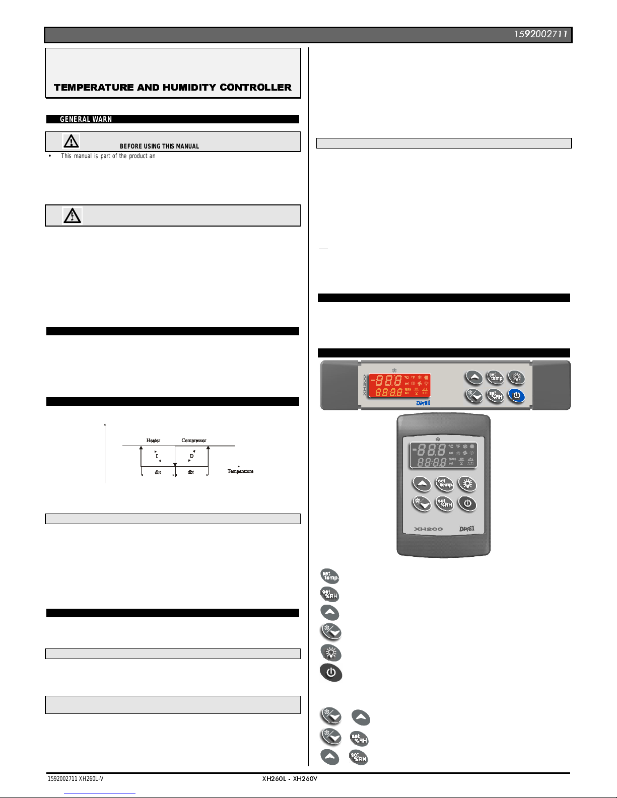
2. GENERAL DESCRIPTION
The
XH260L, 38x185
format, and the
XH260V, 100x64
format, are microproc essor control lers, suit able
for applications on medium or low temperature refrigerating units. They control both humidity and
temperature. They have 6 output relays to control compressor, heating elements, defrost, fan dehumidifier and humidi fier. They have 2 NTC inputs one for thermos tat the other one for defrost. It’ s als o
present and 4÷20mA input for humidity. There is one digital input (free contact) configurable by
parameter. An output allows the user to programme the parameter list with the
“Hot Key”.
3. TEMPERATURE REGULATION
The temperature regulation is performed through neutral zone using compressor and heater output
relays.
Set point
OFF
ON
•
Heating
output: CUT IN is “SET_TEMP-dbt”, CUT OUT is when the temperature reaches the set point.
•
Compressor
output CUT IN is “ SET_TEMP + dbt”, CUT O UT is when the tem per atur e r eac hes the set
point.
3.1 DEFROST
Two defrost modes are avai lable through the “
tdF
” parameter: defrost with electri cal heater or hot gas.
The defrost interval is control by means of parameter “
EdF
”: (EdF=in) the defrost i s made every “
IdF
”
time, (EdF=Sd) the interval “IdF” is calcul ate thr ough S m ar t Defros t al gor i t hm (only when the compressor
is ON).
To
disable
the defrost set the
MdF
parameter to
zero
Humidity regulation during a defrost depends on the
Hud
parameter.
With
Hud=no
humidity regulation is disabled.
Con
Hud=yES
humidity regulation is performed also during a defrost.
4. HUMIDITY REGULATION
The humidity regulation is performed through neutral zone, by humidifying dehumidifying actions.
Humidity control can be dis abled setting the
SET_RH
to “nu” value. In this case only the tem perature
control is perform.
4.1 HUMIDIFYING ACTION
The humidifying action is done enabling the humidifier relay when the humidity is lower than the
“SET_RH-dbH” value.
The relay is switch off when humidity reaches the set values.
4.2 DEHUMIDIFYING ACTION WITHOUT DEHUMIDIFIER RELAY (OA1 DIFFERENT FROM DEH) –
STANDARD CONFIGURATION
In this case the dehumidifying action is performed by setting the following parameters in this way:
tHu = c-H kind of dehumidifying by means of heating and compressor relays
oA1 different from dEH:
The heating and compressor outputs are activ ated together when humidi ty is higher than SE T_RH+dbH
value. Outputs are disabled when humidity comes back to the SET_RH value.
4.2.1 Relation between cooling, heating and dehumidifying
1. If is simultaneousl y present a r equest of cooli ng (temp>S ET_TEM P+dbt) and dehumi difyi ng (RH
> SET_RH+dbH): the cooling acti on has the priority over the dehumidifying acti on: only the
compressor relay is energised till the SET_TEMP is reached at this point also the heating rel ay is
enabled.
2. If is simultaneously present a request of heating (tem p< SET_T EMP- dbt) and dehumidi fying (RH
> SET_RH+dbH): the dehumidi fying action has the priority over the heating action: both the
compressor and the heating rel ays are energi sed t ill the humidity set is reached at this point only
the heating relay is enabled.
4.3 DEHUMIDIFYING ACTION WITH DEHUMIDIFIER RELAY (OA1 = DEH)
The configurable relay is used,
(XH260L terminals 3-4, XH260V t er min als 11-12)
setting the parameter
oA1 =dEH.
NOTE:
the LIGHT button is not more available;
Two kinds of de-humidifying are available:
4.3.1 Dehumidifying action with ONLY de-humidifier relay
By setting the parameter
tHu = db
the de-humidifying ac tion is per formed by enabl ing the de-humidi fier
relay when the humidity is higher than SET_RH + dbH.
The relay is switch off when humidity comes back to the SET_RH value.
4.3.2 Dehumidifying action with de-humidifier and compressor relays
By setting the parameter
tHu = cHu
the de-humidifying ac ti on i s per for m ed by enabl i ng the de- hum i difier
and compressor relays together. when the humidity is higher than SET_RH + dbH.
The relays are switched off when humidity comes back to the SET_RH value.
If is simultaneousl y present a request of cooling (temp>SET_TEMP +dbt) and dehumidifying (RH >
SET_RH+dbH): the cooling action has the priority over the dehumidifying action: onl y the compressor
relay is energised till the SET_TEMP is reached at this point also the de-humidifier is enabled.
5. FA NS
The fan control mode is selected by means of the “
FnC
” parameter:
FnC=C-n
fans will switch ON and OFF with the compressor and
not run
during defrost:;
FnC= O-n
fans will run co ntinuously, but not during defrost
FnC=C-y
fans will switch ON and OFF with the compressor and
run
during defrost;
FnC=O-y
fans will run continuously also during defrost
6. THE DISPLAY
To display and modify target temperature set point. (SET_TEMP)
To display and modify target humidity set point (SET_RH); in programming mode it selects a
parameter or confirm an operation.
In programming mode it browses the parameter codes or increases the displayed value.
To start a manual defrost: hold it pressed for at least 3s.
In programming mode it browses the parameter codes or decreases the displayed value.
Switch ON and OFF the light, if present (oA1=lig)
Switch ON and OFF the instrument.
KEY COMBINATIONS
+
To lock and unlock the keyboard
+
To enter the programming mode.
+
To exit the programming mode.
Page 2
2SHUDWLQJLQVWUXFWLRQV
1592002711 XH260L-V GB r1.0 12.01.04.doc
;+/ ;+9
2/4
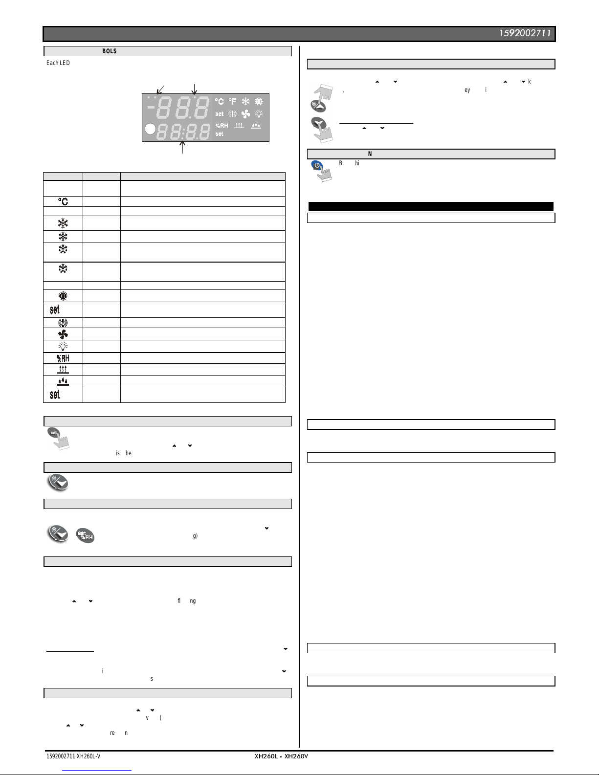
6.1 ICONS AND SYMBOLS
Each LED function is described in the following table.
LED2
LED3
LED4
Temperature
Display
Humidity
Display
LED MODE FUNCTION
Led 4
ON - Instrument in stand by.
- In “Pr2” indicates that the parameter is also present in “Pr1”.
ON °C
°F
ON °C
ON The compressor is running
FLASHING - Anti-short cycle delay enabled
LED 3
ON The defrost is enabled
LED 3
FLASHING Drip time in progress
LED 2
FLASHING Programming Phase (flashing with LED3)
ON Heating enabled
(temp)
FLASHING Temperature Set programming phase
ON - ALARM signal
ON Fan is running
ON The light is on
ON RH%
ON Dehumidifying enabled
ON Humidifying enabled
(umid)
FLASHING Humidity Set programming phase
6.2 HOW TO SEE AND MODIFY THE SET POINT (TEMPERATURE AND HUMIDITY)
1. Push and immediatel y release the SET key: the display will show the Set point
valueand the correspondant set icon starts flashing;
2. To change the Set value push the
9
9
or
8
8
arrows within 10s.
3. To memorise the new set point value push the SET key again or wait 10s.
6.3 TO START A MANUAL DEFROST
1. Push the DOWN key for more than 2 seconds and a manual defrost will start.
6.4 TO ENTER IN PARAMETERS LIST “PR1”
To enter the parameter list “Pr1” (user accessible parameters) operate as follows:
+
1. Enter the Programmi ng mode by pressing the SET_RH+
8
8
for few
seconds. (LED2&3 start flashing)
2. The instrument will sho w the first parameter presen t in “Pr1”
6.5 TO ENTER IN PARAMETERS LIST “PR2”
To access parameters in “Pr2”:
1. Enter t he “Pr1” level.
2. Select “Pr2” parameter and press the “ SET_RH ” key.
3. The “PAS” flashing message is displayed, shortly followed by “0 - -” with a flashing zero.
4. Use
9
9
or
8
8
to input the security code in the fl ashing digit; confirm the figure by pres sing “
SET_RH ”.
The security code is “321“.
5. If the security code is correct the acces s to “Pr2” is enabled by pr essing “ SET_RH ” on the last
digit.
Another possibility is the following: after s wi tc hi ng O N the i ns tr um ent the us er c an pus h SET_RH +
8
8
keys within 30 seconds.
NOTE: each parameter in “Pr2” c an be removed or put into “Pr1” (user l ev el) by press i ng SET_RH +
8
8
.
When a parameter is present in “Pr1” LED 4 is on.
6.6 TO CHANGE PARAMETER VALUES
1. Enter the Programming mode.
2. Select the required parameter with
9
9
or
8
8
.
3. Press the “ SET_RH ” key to display its value (LED2&3 start blinking).
4. Use
9
9
or
8
8
to change its value.
5. Press “ SET_RH ” to store the new value and move to the following parameter.
To exit: Press SET_RH + UP or wait 15s without pressing a key.
NOTE: the new programming is stored even when the procedure is exited by waiting the time-out.
6.7 HOW TO LOCK THE KEYBOARD
1.
Keep the
9
9
and
8
8
keys pressed together for more than 3 s the
9
9
and
8
8
keys.
2.
The “POF” message will be displayed and the keyboard is locked. At this poi nt it is
only possible the vi ewing of the set point or the MAX o M in tem perature s tored and
to switch ON and OFF the light, the auxiliary output and the instrument.
TO UNLOCK THE KEYBOARD
Keep the
9
9
and
8
8
keys pressed together for more than 3s.
6.8 ON/OFF FUNCTION
By pushing the ON/OFF key, the ins tr um ent shows “OF F” for 5 s ec . and the ON/OFF LED
is switched ON.
During the OFF status, all the relays are switched OFF and the regulations are stopped;
N.B. During the OFF status the LED4 button is lighted.
7. PARAMETER LIST
REGULATION
dbt half dead band width for temperature: (0,1÷25,5°C; 1÷45°F) this band is pl ac e bel ow and abov e
the temperature set point (SET_TEMP). The compressor is enabled when the temperature
increases and reaches the SET_TEMP + dbt value. It i s turned off when it comes back to the
SET_TEMP. The heating output i s enabled when temperatur e is less than SET_TE MP -dbt value
and disabled when the SET_TEMP is reached.
dbHhalf dead band width for humidity: (0,5÷25,5RH) this band is place below and above the
humidity set point (SET_RH). The dehumidifying action is enabled when the humidity increases and
reaches the SET_RH + dbH value. It is stopped when it comes back to the SET_RH. The
humidifying output is enabl ed when humidi ty is l ess than S ET_RH -dbH val ue and disabl ed when
the SET_RH is reached.
LS Minimum temperature set point limit: (-50,0°C
÷
SET; -58°F ÷SET) S ets the mi nim um acc eptable
value for the set point.
US Maximum temperature set point limit: (SET
÷
110°C; SET÷230° F) S et the maximum acceptable
value for set point.
OdS Output s act ivatio n d elay at st ar t u p: ( 0÷255 min) Thi s func ti on i s enabl ed at the initial start up of
the instrument and inhibits any output acti vation for the peri od of time set in the par ameter. (Light
can work)
AC Anti-short cycle delay: (0÷30 min) interval between the compressor stop and the following restart.
tHu Kind of de-humidifying: db: only with de-humidifier relay (oA1= dEH)
cHu with de-humidifier and compressor relay (oA1= dEH)
c-H: without de-humidifier relay, by means of compressor and heating relays (oA1≠ dEH).
LSH Minimum humidity set point limit: (Lci ÷ Set H) Sets the minimum acceptabl e value for the
humidity set point.
USH Maximum humidity set point limit: (Set H ÷ uci) Set the maximum acceptable value for
humidity set point.
DISPLAY
CF Measurement unit: °C= Celsius; °F= Fahrenheit
rES Resol uti on (for °C): allows decimal point display. dE = 0,1°C; in = 1 °C
rEH Resolution for RH%: in = integer; Hd= half digit.
DEFROST
tdF Defrost type: rE = electrical heater (Compressor OFF)
in = hot gas (Compressor and defrost relays ON)
EdF Defrost mode: in = interval mode. The defrost starts when the time “Idf” is expired.
Sd = Smartfrost mode. The time IdF (interval between defrosts) is increased only when the
compressor is running (even non consecutively).
SdF Set point for SMARTFROST: (-30
÷
30 °C/ -22÷86 °F) evaporator temperature which allows the IdF
counting (interval between defrosts) in SMARTFROST mode.
dtE Defrost termination temperature: (-50,0÷110,0°C; -58÷230°F) (Enabled only when the
evaporator probe is present) sets the temperatur e m easur ed by the ev apor ator pr obe whi c h c aus es
the end of defrost.
IdF Interval between defrosts: (1÷ 120h) Deter mines the time i nterval between the beginning of two
defrost cycles.
MdF Duration of defrost: (0÷255 m i n) W hen P2P = n, no evaporator probe, it sets the defrost dur ati on,
when P2P = y, defrost end based on temperature, it sets the maximum length for defrost.
dFd Display during defrost: rt = real temperature; it = temperature reading at the defrost start;
Set = set point; dEF = “dEF” label; dEG = “dEG” label;
dAd Defrost displa y time out: (0
÷
255 min) Sets the maxim um time between the end of defrost and the
restarting of the real room temperature display.
Fdt Drain down time: (0÷60 m in.) time i nterv al between reac hing defr ost term inati on temperatur e and
the restoring of the control’s normal oper ation. This time al lows the evaporator to el iminate water
drops that might have formed due to defrost.
dPO First defrost after start-up: y = Immediately; n = after the IdF time
Hud Humidity control during defrost: no: the humidity control is stopped dur ing the defrost; yES the
humidity control works also during the defrost.
FANS
FnC Fan operating mode: C-n = running when a load is on, OFF during the defrost;
C-y = running when a load is on, ON during the defrost;
O-n = continuous mode, OFF during the defrost; O-y = continuous mode, ON during the defrost;
TEMPERATURE ALARMS
ALC Temperature alarm configuration: rE = High and Low alarms related to Set Point
Ab = High and low alarms related to the absolute temperature.
ALL Low temperature alarm setting:ALC = rE , 0
÷
50 °C or 90°F
ALC = Ab , - 50°C or -58°F
÷
ALU
when this temperature is reached and after the ALd delay time, the LA alarm is enabled,.
ALU High temperature alarm setting: ALC= rE, 0
÷
50°C or 90°F
ALC= Ab, ALL
÷
110°C or 230°F
when this temperature is reached and after the ALd delay time the HA alarm is enabled.
Page 3

2SHUDWLQJLQVWUXFWLRQV
1592002711 XH260L-V GB r1.0 12.01.04.doc
;+/ ;+9
3/4
ALH Temperature alarm recovery differential: (0,1÷25,5°C; 1÷45°F) Intervention differential for
recovery of temperature alarm.
ALd Temperature alarm delay: (0÷255 min) ti me inter val between the detecti on of an alarm condi tion
and the corresponding alarm signalling.
dAO Delay of temperature alarm at start-up: (0min÷23h 50min) time interval between the detection of
the temperature alarm condition after the instrument power on and the alarm signalling.
EdA Alarm delay at the end of defrost: (0
÷
255 min) Time interv al between the detection of the
temperature alarm condition at the end of defrost and the alarm signalling.
dot Delay of temperature alarm after closing the door : (0
÷
255 min) Time delay to signal the
temperature alarm condition after closing the door.
HUMIDITY ALARMS
AHC Humidity alarm configuration: rE = High and Low alarms related to humidity Set Point
Ab = High and low alarms related to the “absolute” humidity.
AHL Low humidity alarm setting: (with AHC = rE: 0 ÷ 50. With AHC = Ab: Lci ÷ AHu)
when this humidity is reached and after the AHd delay time, the HLA alarm is enabled,.
AHu High humidity alarm setting: (with AHC = rE: 0÷50°C. with AHC = Ab: AHL ÷ uci
when this humidity is reached and after the AHd delay time the HHA alarm is enabled.
AHH Humidity alarm recovery differ ential: (0.5÷20.0) Interventi on differenti al for recov ery of humi dity
alarm.
AHd Humidity alarm delay: (0÷ 255 mi n) time interval between the detection of an alar m conditi on and
the corresponding alarm signalling.
dHo Delay of humidity alarm at start-up: (0min÷23h 50min) time interval between the detection of the
humidity alarm condition after the instrument power on and the alarm signalling.
doH Alarm delay at the end of defrost: (0
÷
255 min) Time interv al between the detection of the
humidity alarm condition at the end of defrost and the alarm signalling.
doA Open door alarm delay:(0÷ 255 min) delay between the detection of the open door condition and
its alarm signalling: the flashing message “dA” is displayed.
nPS Pressure switch number: (0
÷
15) Number of activation of the pres sure switch, during the “did”
interval, before signalling the alarm event (I2F= PAL).
If the nPS activation in t he “ did ” t ime is r eached , swit ch o ff an d on the instr u ment t o r est ar t
normal regulation.
PROBE INPUTS
Ot Thermostat probe calibration: (-12.0÷12.0°C/ -21÷21°F) al lows to adjust possible offs et of the
thermostat probe.
OE Evaporator probe calibration: (-12.0
÷
12.0°C/ -21÷21°F) al lows to adjust possi ble offsets of the
evaporator probe.
O3 Humidity probe calibration: (-10÷10 RH) allows to adjust possible offsets of the humidity probe.
P2P Evaporator probe presence: n= not present: the defrost stops only by ti me; y= present: the
defrost stops by temperature and time.
P3P Humidity probe presence: n= not present; y= present.
LCI Readout with 4 mA : (-999 ÷ 999). Adjustment of read out corresponding to 4mA signal.
UCI Readout with 20 mA : (-999 ÷ 999). Adjustment of read out corresponding to 20mA signal.
DIGITAL INPUTS
i1P Digital input polarity: CL : the digital input is activated by closing the contact; OP : the digital input
is activated by opening the contact
i1F Digital input operating mode: configure the digital input function: EAL = generic alarm; bAL =
serious alarm mode; PAL = Pressure switch; Ht = heating relay safety; dor = door switch
odc Outputs status when open door: on = normal; Fan = Fan OFF; oFF = all the loads off
rrd Outputs r estar ting after doA alar m: no = outputs not affec ted by the doA al arm; yES = outputs
restart with the doA alarm;
did Time interval/delay for digital input alarm:(0
÷
255 min.) Time interv al to calc ulate the number of
the pressure switch acti v ati on when I1F= P A L. If I1F= E A L or bA L (ex ter nal alarms), “di d” par am eter
defines the time delay between the detection and the successive signalling of alarms.
OTHER
oA1 Light relay configuration (XH260L terminals 3-4, XH260V termin als. 11- 12): ALr = alar m; dEH
= dehumidifier; onF = on/off r elay: close wi th instrument on, open with instr ument off; Lig = light,
ESt, dEF not select
Adr RS485 serial address (0÷247) identifies the instrument within a control or supervising system.
Ptb Parameter table: (read only) it shows the original code of the
parameter map.
rEL Software release: (read only) Software version of the microprocessor.
Prd Probes display: (read only) display the temperature values of the evaporator probe Pb2.
Pr2 Access to the protected parameter list (read only).
8. DIGITAL INPUT
One digital input is present configurable by user by means of the i1F parameter according to the following
descriptions.
8.1 DOOR SWITCH (I1F = dor)
It signals the door status and the corresponding rel ay output status through the “odc” parameter: no =
normal (any change); Fan = Fan OFF; oFF = all the loads are switched off.
Since the door is opened, after the delay tim e set through par ameter “dOA”, the alar m output is enabl ed
and the display shows the message “dA”.
The status of loads depends on the “rrd” parameter:
with rrd=no outputs are not affected by the doA alarm;
with rrd=yES = outputs restart with the doA alarm;
The alarm stops as soon as the external digi tal i nput is di sabl ed again. Duri ng thi s tim e and then for the
delay “dot” and “doH” after closing the door, the temperature and humidity alarms are disabled.
8.2 GENERIC ALARM (I1F = EAL)
As soon as the digital input is ac tivated the unit w ill wait for “did” time delay before signalling the “EAL”
alarm message. The outputs s tatus don’t change. The alarm stops just after the digi tal input is deactivated.
8.3 SERIOUS ALARM MODE (I1F = BAL)
When the digital input is ac tivated, the unit will wait for “did” delay before signalling the “bAL” alarm
message. The relay outputs ar e switched OFF. The al arm will stop as soon as the digital input is deactivated.
8.4 PRESSURE SWITCH (I1F = PAL )
If during the interval time set by “did” param eter, the pressure switch has reached the number of
activation of the “nPS” parameter, the “PAL” pressure alarm message will be displayed. The compresso r
and the regulation are stopped. When the digital input is ON the compressor is always OFF.
If the nPS activation in t he d id t ime is reached, switch off and on t he in st r umen t to r est ar t n or mal
regulation.
8.5 HEATING RELAY SAFETY (i1F=Ht)
With i1F=Ht as soon as the digital input is activated for “did” time heating relay is disabled.
The alarm will stop as soon as the digital input is de-activated.
8.6 DIGITAL INPUTS POLARITY
The digital input polarity depends on the “i1P” parameters.
CL : the digital input is activated by closing the contact.
OP : the digital input is activated by opening the contact
9. INSTALLATION AND MOUNTING
Instruments XW240L shall be mounted on vertical panel, in a 150x31 m m hole, and fixed using two
screws
∅
3 x 2mm. To obtain an IP65 protection grade use the front panel rubber gasket (mod. RG-L).
Instrument XH260V s hal l be m ounted on v er t i c al panel , i n a 72x 56 m m hole, and fixed using sc r ews
∅
3
x 2mm. To obtain an IP65 protection grade use the front panel rubber gasket (mod. RG-V).
The temperature range allowed for correct operation is 0 - 60 °C. Avoid places subject to strong
vibrations, corros ive gas es, exc essi ve di rt or hum idi ty. T he same r ecomm endations apply to probes. Let
the air circulate by the cooling holes.
9.1 XH260V: CUT OUT
56
7
2
40
8
3
,
5
9.2 XH260L: CUT OUT
165
150
31
+0.5
-0
+0.5
-0
+1
-1
Ø3 x2
10. ELECTRICAL CONNECTIONS
The instruments are provi ded with s crew ter mi nal bl ock to c onnect cables wi th a cr oss sec tion up to 2,5
mm
2
for the digital and analogue inputs . Relays and power suppl y have a Faston connec tion (6,3mm ).
Heat-resistant cables hav e to be used. Before connec ting cabl es make s ure the power supply com plies
with the instrument’s r equirements. Separate the pr obe cables from the power s upply cables , from the
outputs and the power connections. Do not exceed the m axim um c urrent al lowed on each relay , i n c ase
of heavier loads use a suitable external relay.
N.B. Maximum current allowed for all the loads is 20A.
10.1 PROBE CONNECTIONS
The probes shall be mounted with the bulb upwards to prevent damages due to casual liquid infiltration. It
is recommended to place the thermostat probe away from ai r stream s to corr ectly m easure the aver age
room temperature.
11. HOW TO USE THE HOT KEY
11.1 HOW TO PROGRAM A HOT KEY FROM THE INSTRUMENT (UPLOAD)
1. Program one controller with the front keypad.
2. When the controller is ON, ins ert the “Hot key” and push
9
9
key; the "uPL" message appears
followed a by flashing “End”
3. Push “SET” key and the End will stop flashing.
4. Turn OFF the instrument remove the “Hot Key”, then turn it ON again.
NOTE: the “Err” message is displayed for failed programming. In this case push again
9
9
key if you want
to restart the upload again or remove the “Hot key” to abort the operation.
11.2 HOW TO PROGRAM AN INSTRUMENT USING A HOT KEY (DOWNLOAD)
1. Turn OFF the instrument.
2. Insert a programmed “Hot Key” into the 5 PIN receptacle and then turn the Controller ON.
3. Automatically the param eter li st of the “Hot Key” is downloaded into the Control ler mem ory, the
“doL” message is blinking followed a by flashing “End”.
4. After 10 seconds the instrument will restart working wit h the new pa r ameters.
5. Remove the “Hot Key”..
NOTE the message “Err” is displ ayed for fai led pr ogramm ing. In thi s c ase turn the uni t off and then on if
you want to restart the download again or remove the “Hot key” to abort the operation.
Page 4

2SHUDWLQJLQVWUXFWLRQV
1592002711 XH260L-V GB r1.0 12.01.04.doc
;+/ ;+9
4/4
12. ALARM SIGNALLING
Message Cause Outputs
“P1” Thermostat probe failure Compressor and heating outputs off
“P2” Evaporator probe failure Defrost and by time
“P3” Humidity probe failure Humidity regulation off
“HA” High temperature alarm Outputs unchanged
“LA” Low temperature alarm Outputs unchanged
“HHA” High humidity alarm Outputs unchanged
“HLA” Low humidity alarm Outputs unchanged
“dA” Door switch alarm Outputs depending on the odC parameter
“EAL” External alarm Other outputs unchanged
“BAL” Serious external alarm Outputs OFF
“PAL” Pressure switch alarm Outputs OFF
The alarm message is displayed until the alarm condition recoveries.
All the alarm mes sages are showed alter nating with the room temperature ex cept for the “P1” which is
flashing. To reset the “EE” alarm and restart the normal functioni ng press any key, the “
rSt
” message is
displayed for about 3s.
12.1 SILENCING BUZZER
Once the alarm signal is detected the buzzer, if present, can be silenced by pressing any key.
12.2 ALARM RECOVERY
Probe alarms
: “P1” (probe1 faulty), “P2”, “P3”; they automatically stop 10s after the probe rest arts
normal operation. Check connections before replacing the probe.
Temperature alarms “HA
” and “LA” automatically stop as s oon as the ther m os tat tem per ature r etur ns to
normal values or when the defrost starts.
Humidity alarms “HHA
” and “
LHA
” automatically stop as soon as the humidity returns to normal values.
Door switch alarm “dA
” stop as soon as the door is closed.
External alarms “EAL
”, “
BAL
” stop as soon as the external digital input is disabled
Pressure switch alarm “PAL” alarm is recovered by switching OFF the instrument
.
13. TECHNICAL DATA
Housing:
self extinguishing ABS.
Case: XH260L:
facia 38x185 mm; depth 76mm;
XH260V:
facia 100x64 mm; depth 76mm
Mounting: XH260L:
panel mounting in a 150x31 mm panel cut-out with two screws.
∅
3 x 2mm.
Distance between the holes 165mm
XH260V:
panel mounting in a 56x72 mm panel c ut-out with two screws.
∅
3x2mm. Distance
between the holes 40mm
Protection:
IP20.
Frontal protection:
IP65 with optional frontal gasket mod. RG-L (XH260L); RGW-V (XH260V)..
Connections:
Screw terminal block
≤
2,5 mm2 heat-resistant wiring and 6,3mm Faston
Power supply:
230Vac or 110Vac
±
10%;
Power absorption:
7VA max.
Display
: double display + icons.
Inputs
: 1 NTC probe + 4÷20mA probe
Digital input
: 1 free voltage
Relay outputs: compressor: XH260L:
relay SPST 20(8) A, 250Vac;
XH260V:
relay SPST 8(3) A, 250Vac
heather:
relay SPST 8(3) A, 250Vac;
defrost:
relay SPST 8(3) A, 250Vac
fans:
relay SPST 8(3) A, 250Vac;
humidifier:
relay SPST 8(3) A, 250Vac
de-humidifier:
relay SPST 8(3) A, 250Vac
Other output :
alarm buzzer (optional)
Data storing
: on the non-volatile memory (EEPROM).
Kind of action:
1B.;
Pollution grade:
normal;
Software class:
A.
Operating temperature:
0÷60 °C.;
Storage temperature:
-25÷60 °C.
Relative humidity:
20
÷
85% (no condensing)
Measuring and regulation range:
NTC probe:
-40÷110°C (-58÷230°F)
Resolution:
0,1 °C or 1°C or 1 °F (selectable).
Accuracy (ambient temp. 25°C)
: ±0,5 °C ±1 digit
14. WIRING CONNECTIONS
14.1 XH260L
Room
L
N
Comp
20(8)A
250V
a
Fan
8(3)A
250V
a
8(3)A
250V
a
8(3)A
250V
a
8(3)A
250V
a
Def
Heater
Hum
8(3)A
250V
a
Def
NC
Supply 115Vac
: 14-15 terminals
14.2 XH260V
8(3)A
250V
a
MAX
20A
Comp
Def
N.C.
Fan
Room
Def.
Heater
8(3)A
8(3)A
8(3)A
8(3)A
8(3)A
C
Hum
Supply 115Vac: 2-3 terminals
15. DEFAULT SETTING VALUES
Label
Value Menu Description Range
Set T
5.0 - - - Temperature Set Point LS ÷ uS ( nu = temperature
regulation disabled )
Set H
50.0 - - - Humidity Set Point LSH ÷ uSH ( nu = humidity
regulation disabled)
dbt
2.0 Pr1 Half dead band width for temperature 0.1°C o 1°F ÷ 25°C o 77°F
dbH
5.0 Pr1 Half dead band width for humidity 0.5 ÷ 50
LS
-40 Pr2 Minimum temperature set point limit -50.0°C o –58°F ÷ Set T
uS
110 Pr2 Maximum temperature set point limit Set T ÷ 110°C o 230°F
odS
1 Pr2 Outputs activation delay at start up 0 ÷ 250 min
Ac
1 Pr1 Anti-short cycle delay 0 ÷ 30 min
tHu
db Pr2 Humidity regulation db = dehumidifier relay.; cHu
= dehum+ compr.; c-H=
without dehum. relay
LSH
0.0 Pr2 Minimum humidity set point limit Lci ÷ Set H
uSH
100.0 Pr2 Maximum humidity set point limit Set H ÷ uci
cF
°C Pr2 Measurement unit °C ÷°F
rES
dE Pr2 Resolution (for °C): in = integer / dE = decimal
rEH
Hd Pr2 Resolution for RH%: in = integer / Hd = half digit
tdf
rE Pr2 Defrost type rE, rT, in
EdF
in Pr2 Defrost mode In, Sd
SdF
0 Pr2 Set point for SMART DEFROST -30 ÷ +30°C / -22÷+86°F
dtE
8 Pr2 Defrost termination temperature -50,0÷110°C/ -58÷230°F
idF
8 Pr1 Interval between defrosts 1 ÷ 120 h
MdF
20 Pr1 Duration of defrost 0 ÷ 250 min
dFd
it Pr2 Display during defrost rt / it / SEt / dEF / dEG
dAd
30 Pr2 Defrost display time out 0 ÷ 250 min
Fdt
0 Pr2 Draining time 0÷60 min.
dPo
no Pr2 First defrost after start up n ÷ y
Hud
no Pr2 Humidity control during defrost no; yES
Fnc
c-n Pr2 Fan operating mode c-n / c-Y / o-n / o-Y
ALc
Ab Pr2 Temperature alarm configuration rE = relative / Ab = absolute
ALL
-40.0 Pr1 Low temperature alarm setting
0°C ÷ 50.0°C / -50.0°C ÷ ALu
ALu
110 Pr1 High temperature alarm setting
0°C ÷ 50.0°C / ALL ÷ 110°C
ALH
1.0 Pr2 Temperature alarm recovery differential 0.1°C o 1°F ÷ 25°C o 77°F
ALd
15 Pr2 Temperature alarm delay 0 ÷ 250 min
dAo
1.3 Pr2 Delay of temperature alarm at start-up 0.0 ÷ 23.5 h
EdA
20 Pr2 Alarm delay at the end of defrost 0 ÷ 250 min
dot
20 Pr2
Delay of temperature alarm after c losing the
door
0 ÷ 250 min
AHc
Ab Pr2 Humidity alarm configuration rE = relative / Ab = absolute
AHL
0.0 Pr1 Low humidity alarm setting 0 ÷ 50 / Lci ÷ AHu
AHu
100 Pr1 High humidity alarm setting 0 ÷ 50 / AHL ÷ uci
AHH
2.0 Pr2 Humidity alarm recovery differential 0.5 ÷ 25
AHd
15 Pr2 Humidity alarm delay 0 ÷ 250 min
dHo
1.3 Pr2 Delay of humidity alarm at start-up 0.0 ÷ 23.5 h
doH
20 Pr2 Alarm delay at the end of defrost 0 ÷ 250 min
nPS
0 Pr2 Pressure switch number 0÷15
doA
20 Pr2 Open door alarm delay 0 ÷ 250 min ( 250 = nu )
ot
0.0 Pr1 Thermostat probe calibration -12.0 ÷ 12.0
oE
0.0 Pr2 Evaporator probe calibration -12.0 ÷ 12.0
o3
0.0 Pr1 Humidity probe calibration -10 ÷ 10
P2P
no Pr2 Evaporator probe presence no = absent / YES = present
P3P
YES Pr2 Humidity probe presence no = absent / YES = present
Lci
0 Pr2 Readout with 4 mA -999 ÷ 999
uci
100 Pr2 Readout with 20 mA -999 ÷ 999
i1P
oP Pr2 Digital input polarity cL =open / oP = close
i1F
dor Pr2 Digital input configuration dor / PAL / EAL / bAL / Ht
odc
oFF Pr2 Outputs status when open door on / Fan / oFF
rrd
YES Pr2 Outputs restarting after doA alarm no = no / YES = yes
did
0 Pr2 Digital input alarm delay 0÷255 min.
oA1
Lig Pr2
Light relay configuration (XH260L
terminals 3-4, XH260V terminals. 11-12):
ALr = alarm; dEH =
dehumidifier; onF = on/off; Lig
= light, ESt, dEF not select
Adr
1 Pr2 Serial address 0÷247 num
Ptb
1 Pr2 Parameter table - - -
rEL
0.1 Pr2 Software release - - -
Prd
-- Pr2 Probes display Pb1÷Pb3
Pr2
321 Pr1 Access to the protected parameter list - - -
Dixell s.r.l. Via dell’Industria, 27 - 32010 Z.I Pieve d’Alpago (BL) ITALY
tel. +39 - 0437 - 98 33 - fax +39 - 0437 - 98 93 13
(PDLOGL[HOO#GL[HOOFRP KWWSZZZGL[HOOFRP
 Loading...