

Page 1
dIXEL
Operating instructions
1592002750
1592002750 XH240K GB r1.0 15.06.2004 * XH240K 1/4
XH240K
TEMPERATURE AND HUMIDITY CONTROLLER
1. GENERAL WARNING
1.1 PLEASE READ BEFORE USING THIS MANUAL
• This manual is part of the product and should be kept near the instrument for easy and quick
reference.
• The instrument shall not be used for purposes different from those described hereunder. It cannot
be used as a safety device.
• Check the application limits before proceeding.
1.2
SAFETY PRECAUTIONS
• Check the supply voltage is correct before connecting the instrument.
• Do not expose to water or moisture: use the controller only within the operating limits avoiding
sudden temperature changes with high atmospheric humidity to prevent formation of
condensation
• Warning: disconnect all electrical connections before any kind of maintenance.
• Fit the probe where it is not accessible by the End User. The instrument must not be opened.
• In case of failure or faulty operation send the instrument back to the distributor or to “Dixell s.r.l.”
(see address) with a detailed description of the fault.
• Consider the maximum current which can be applied to each relay (see Technical Data).
• Ensure that the wires for probes, loads and the power supply are separated and far enough from
each other, without crossing or intertwining.
• In case of applications in industrial environments, the use of mains filters (our mod. FT1) in
parallel with inductive loads could be useful.
2. GENERAL DESCRIPTION
The XH240K is microprocessor controller suitable for applications on medium temperature
refrigerating units. It must be connected by means of a two-wire cable (∅ 1mm) at a distance of
up to 30 meters to the keyboard VH620, 100x64mm format. It controls both humidity and
temperature. It has 4 output relays to control compressor, heating elements , fan and humidifier.
It has 2 analogue inputs: one for temperature control, the other for humidity. There is one digital
input (free contact). An output allows the user to programme the parameter list with the “Hot
Key”.
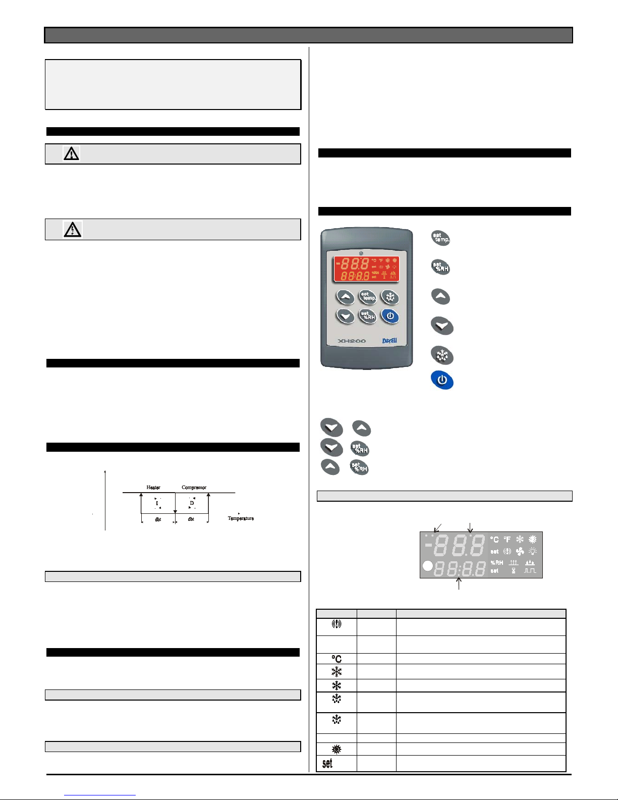
3. TEMPERATURE REGULATION
The temperature regulation is performed through neutral zone using compressor and heater
output relays.
Set point
OFF
ON
• Heating output: CUT IN is “SET_TEMP-dbt”, CUT OUT is when the temperature reaches the
set point.
• Compressor output CUT IN is “ SET_TEMP +dbt”, CUT OUT is when the temperature
reaches the set point.
3.1 DEFROST
During the defrost temperature regulation is disabled.. Parameter “IdF” controls the interval
between defrost cycles, while its length is controlled by parameter “MdF”.
To disable defrost set the MdF parameter to zero.
Humidity regulation, during defrost, depends on the Hud parameter. With
Hud=no humidity regulation is disabled during defrosts.
Hud=yES humidity regulation is performed also during defrosts.
4. HUMIDITY REGULATION
The humidity regulation is performed through neutral zone, by humidifying dehumidifying.
Humidity control can be disabled setting the SET_RH to “nu” value. In this case only the
temperature control is perform.
4.1 HUMIDIFYING ACTION
The humidifying action is done enabling the humidifier relay when the humidity is lower than the
“SET_RH-dbH” value.
The relay is disable when humidity reaches the set values.
4.2 DEHUMIDIFYING ACTION
The dehumidifying action is performed enabling the heating and compressor output together
when humidity is higher than SET_RH+dbH value.
Outputs are disabled when humidity comes back to the SET_RH value.
4.2.1 Relation between cooling, heating and dehumidifying
1. If is simultaneously present a request of cooling (temp>SET_TEMP+dbt) and
dehumidifying (RH > SET_RH+dbH): the cooling action has the priority over the
dehumidifying action: only the compressor relay is energised till the SET_TEMP is
reached at this point also the heating relay is enabled.
2. If is simultaneously present a request of heating (temp< SET_TEMP-dbt) and
dehumidifying (RH > SET_RH+dbH): the dehumidifying action has the priority over the
heating action: both the compressor and the heating relays are energised till the humidity
set is reached at this point only the heating relay is enabled.
5. FANS
The fan control mode is selected by means of the “FnC” parameter:
C-n = running when a load is on, OFF during the defrost;
C-y = running when a load is on, ON during the defrost;
O-n = continuous mode, OFF during the defrost;
O-y = continuous mode, ON during the defrost;
6. THE DISPLAY
To display and modify target
temperature set point. (SET_TEMP)
To display and modify target humidity
set point (SET_RH); in programming
mode it selects a parameter or confirm
an operation.
In programming mode it browses the
parameter codes or increases the
displayed value.
In programming mode it browses the
parameter codes or decreases the
displayed value.
By holding it pressed for 3s the defrost
is started..
Switch ON and OFF the instrument.
KEY COMBINATIONS
+
To lock and unlock the keyboard
+
To enter the programming mode.
+
To exit the programming mode.
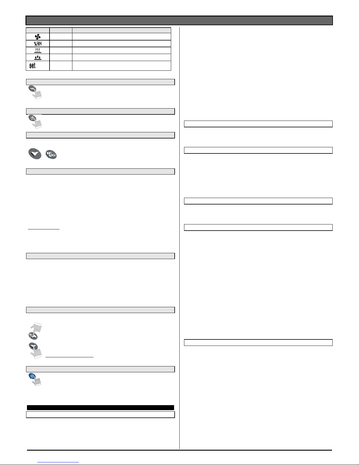
6.1 ICONS AND SYMBOLS
Each LED function is described in the following table.
LED2 LED3
LED4
Temperature Display
Humidity Display
LED MODE FUNCTION
ON - ALARM signal
Led 4
ON - Instrument in stand by.
- In “Pr2” indicates that the parameter is also present in “Pr1”.
ON °C
ON The compressor is running
FLASHING - Anti-short cycle delay enabled
LED 3
ON The defrost is enabled
LED 3
FLASHING Drip time in progress
LED 2
FLASHING Programming Phase (flashing with LED3)
ON Heating enabled
(temp)
FLASHING Temperature Set programming phase
Page 2
dIXEL
Operating instructions
1592002750
1592002750 XH240K GB r1.0 15.06.2004 * XH240K 2/4
LED MODE FUNCTION
ON Fan is running
ON RH%
ON Dehumidifying enabled
ON Humidifying enabled
(umid)
FLASHING Humidity Set programming phase
6.2 HOW TO SEE AND MODIFY THE SET POINT (TEMPERATURE AND HUMIDITY)
1. Push and immediately release the SET key: the display will show the Set point
valueand the correspondant set icon starts flashing;
2. To change the Set value push the o or n arrows within 10s.
3. To memorise the new set point value push the SET key again or wait 10s.
6.3 TO START A MANUAL DEFROST
1. Push the DEF key for more than 2 seconds and a manual defrost will start.
6.4 TO ENTER IN PARAMETERS LIST “PR1”
To enter the parameter list “Pr1” (user accessible parameters) operate as follows:
+
1. Enter the Programming mode by pressing the SET_RH+ n for
few seconds. (LED2&3 start flashing)
2. The instrument will show the first parameter present in “Pr1”
6.5 TO ENTER IN PARAMETERS LIST “PR2”
To access parameters in “Pr2”:
1. Enter the “Pr1” level.
2. Select “Pr2” parameter and press the “ SET_RH ” key.
3. The “PAS” flashing message is displayed, shortly followed by “0 - -” with a flashing zero.
4. Use o or n to input the security code in the flashing digit; confirm the figure by pressing “
SET_RH ”.
The security code is “321“.
5. If the security code is correct the access to “Pr2” is enabled by pressing “ SET_RH ” on the
last digit.
Another possibility is the following: after switching ON the instrument the user can push
SET_RH + n keys within 30 seconds.
NOTE: each parameter in “Pr2” can be removed or put into “Pr1” (user level) by pressing
SET_RH + n. When a parameter is present in “Pr1” LED 4 is on.
6.6 HOW TO CHANGE THE PARAMETER VALUE
1. Enter the Programming mode.
2. Select the required parameter with o or n.
3. Press the “ SET_RH ” key to display its value (LED2&3 start blinking).
4. Use o or n to change its value.
5. Press “ SET_RH ” to store the new value and move to the following parameter.
To exit: Press SET_RH + UP or wait 15s without pressing a key.
NOTE: the new programming is stored even when the procedure is exited by waiting the time-
out.
6.7 HOW TO LOCK THE KEYBOARD
1.
Keep the o and n keys pressed together for more than 3 s the o and n
keys.
2.
The “POF” message will be displayed and the keyboard is locked. At this
point it is only possible the viewing of the set point or the MAX o Min
temperature stored and to switch ON and OFF the light, the auxiliary output
and the instrument.
TO UNLOCK THE KEYBOARD
Keep the o and n keys pressed together for more than 3s.
6.8 ON/OFF FUNCTION
By pushing the ON/OFF key, the instrument shows “OFF” for 5 sec. and the
ON/OFF LED is switched ON.
During the OFF status, all the relays are switched OFF and the regulations are
stopped;
N.B. During the OFF status the LED4 button is lighted.
7. PARAMETER LIST
REGULATION
dbt half dead band width for temperature: (0,1÷25,5°C; 1÷45°F) this band is place below
and above the temperature set point (SET_TEMP). The compressor is enabled when the
temperature increases and reaches the SET_TEMP + dbt value. It is turned off when it
comes back to the SET_TEMP. The heating output is enabled when temperature is less
than SET_TEMP -dbt value and disabled when the SET_TEMP is reached.
dbH half dead band width for humidity: (0,5÷25,5RH) this band is place below and above
the humidity set point (SET_RH). The dehumidifying action is enabled when the humidity
increases and reaches the SET_RH + dbH value. It is stopped when it comes back to the
SET_RH. The humidifying output is enabled when humidity is less than SET_RH -dbH
value and disabled when the SET_RH is reached.
LS Minimum temperature set point limit: (-50,0°C÷SET; -58°F÷SET) Sets the minimum
acceptable value for the set point.
US Maximum temperature set point limit: (SET÷110°C; SET÷230°F) Set the maximum
acceptable value for set point.
OdS Outputs activation delay at start up: (0÷255 min) This function is enabled at the initial
start up of the instrument and inhibits any output activation for the period of time set in the
parameter. (Light can work)
AC Anti-short cycle delay: (0÷30 min) interval between the compressor stop and the
following restart.
LSH Minimum humidity set point limit: (Lci ÷ Set H) Sets the minimum acceptable value for
the humidity set point.
USH Maximum humidity set point limit: (Set H ÷ uci) Set the maximum acceptable value for
humidity set point.
DISPLAY
CF Measurement unit: °C= Celsius; °F= Fahrenheit
rES Resolution (for °C): it allows decimal point display. dE=0,1°C; in=1°C
rEH Resolution for RH%: in = integer; Hd= half digit.
DEFROST
IdF Interval between defrosts: (1÷120h) Determines the time interval between the beginning
of two defrost cycles.
MdF Duration of defrost: (0÷255 min) no evaporator probe, it sets the defrost duration.
dFd Display during defrost: rt = real temperature; it = temperature reading at the defrost
start; Set = set point; dEF = “dEF” label; dEG = “dEG” label;
dAd Defrost display time out: (0÷255 min) Sets the maximum time between the end of defrost
and the restarting of the real room temperature display.
Hud Humidity control during defrost: no: the humidity control is stopped during the defrost;
yES the humidity control works also during the defrost.
FANS
FnC Fan operating mode: C-n = running when a load is on, OFF during the defrost;
C-y = running when a load is on, ON during the defrost;
O-n = continuous mode, OFF during the defrost;
O-y = continuous mode, ON during the defrost;
TEMPERATURE ALARMS
ALC Temperature alarm configuration
rE = High and Low alarms related to Set Point
Ab = High and low alarms related to the absolute temperature.
ALL Low temperature alarm setting:
ALC = rE , 0 ÷ 50 °C or 90°F
ALC = Ab , - 50°C or -58°F ÷ ALU
when this temperature is reached and after the ALd delay time, the LA alarm is enabled,.
ALU High temperature alarm setting:
ALC= rE, 0 ÷ 50°C or 90°F
ALC= Ab, ALL ÷ 110°C or 230°F
when this temperature is reached and after the ALd delay time the HA alarm is enabled.
ALH Temperature alarm recovery differential: (0,1÷25,5°C; 1÷45°F) Intervention differential
for recovery of temperature alarm.
ALd Temperature alarm delay: (0÷255 min) time interval between the detection of an alarm
condition and the corresponding alarm signalling.
dAO Delay of temperature alarm at start-up: (0min÷23h 50min) time interval between the
detection of the temperature alarm condition after the instrument power on and the alarm
signalling.
EdA Alarm delay at the end of defrost: (0÷255 min) Time interval between the detection of the
temperature alarm condition at the end of defrost and the alarm signalling.
dot Delay of temperature alarm after closing the door : (0÷255 min) Time delay to signal
the temperature alarm condition after closing the door.
HUMIDITY ALARMS
AHC Humidity alarm configuration: rE = High and Low alarms related to humidity Set Point
Ab = High and low alarms related to the “absolute” humidity.
AHL Low humidity alarm setting: (with AHC = rE: 0 ÷ 50. With AHC = Ab: Lci ÷ AHu)
when this humidity is reached and after the AHd delay time, the HLA alarm is enabled,.
AHU High humidity alarm setting: (with AHC = rE: 0÷50°C. with AHC = Ab: AHL ÷ uci
when this humidity is reached and after the AHd delay time the HHA alarm is enabled.
AHH Humidity alarm recovery differential: (0.5÷20.0) Intervention differential for recovery of
humidity alarm.
AHd Humidity alarm delay: (0÷255 min) time interval between the detection of an alarm
condition and the corresponding alarm signalling.
dHo Delay of humidity alarm at start-up: (0min÷23h 50min) time interval between the
detection of the humidity alarm condition after the instrument power on and the alarm
signalling.
doH Alarm delay at the end of defrost: (0÷255 min) Time interval between the detection of the
humidity alarm condition at the end of defrost and the alarm signalling.
doA Open door alarm delay:(0÷255 min) delay between the detection of the open door
condition and its alarm signalling: the flashing message “dA” is displayed.
nPS Pressure switch number: (0 ÷15) Number of activation of the pressure switch, during the
“did” interval, before signalling the alarm event (I2F= PAL).
If the nPS activation in the “did” time is reached, switch off and on the instrument to
restart normal regulation.
Page 3

dIXEL
Operating instructions
1592002750
1592002750 XH240K GB r1.0 15.06.2004 * XH240K 3/4
PROBE INPUTS
Ot Thermostat probe calibration: (-12.0÷12.0°C/ -21÷21°F) allows to adjust possible offset
of the thermostat probe.
O3 Humidity probe calibration: (-10÷10 RH) allows to adjust possible offsets of the humidity
probe.
P3P Humidity probe presence: yES= probe present; no= probe absent, only the temperature
control is perfomed.
LCI Readout with 4 mA : (-999 ÷ 999). Adjustment of read out corresponding to 4mA signal.
UCI Readout with 20 mA: (-999÷999). Adjustment of read out corresponding to 20mA signal.
DIGITAL INPUTS
i1P Digital input polarity: CL : the digital input is activated by opening the contact; OP :
the digital input is activated by closing the contact
i1F Digital input operating mode: it configures the digital input: EAL = generic alarm; bAL =
serious alarm mode; PAL = Pressure switch; Ht = heating relay safety; dor = door switch
odc Outputs status when open door:
on = normal; Fan = Fan OFF; oFF = all the loads are switched off
rrd Outputs restarting after doA alarm: no = outputs not affected by the doA alarm; yES =
outputs restart with the doA alarm;
did Time interval/delay for digital input alarm:(0÷255 min.) Time interval to calculate the
number of the pressure switch activation when I1F=PAL. If I1F=EAL or bAL (external
alarms), “did” parameter defines the time delay between the detection and the successive
signalling of alarms.
OTHER
Adt RS485 serial address for temperature (0÷247) identifies the instrument within a control
or supervising system.
AdH RS485 serial address for humidity(0÷247) identifies the instrument within a control or
supervising system.
Ptb Parameter table: (read only) it shows the original code of the dIXEL parameter map.
rEL Software release: (read only) Software version of the microprocessor.
Pr2 Access to the protected parameter list (read only).
8. DIGITAL INPUT
One digital input is present configurable by user by means of the i1F parameter according to the
following descriptions.
8.1 DOOR SWITCH (12F = dor)
It signals the door status and the corresponding relay output status through the “odc” parameter:
no = normal (any change); Fan = Fan OFF; oFF = all the loads are switched off.
Since the door is opened, after the delay time set through parameter “dOA”, the alarm output is
enabled and the display shows the message “dA”.
The status of loads depends on the “rrd” parameter:
with rrd=no outputs are not affected by the doA alarm;
with rrd=yES = outputs restart with the doA alarm;
The alarm stops as soon as the external digital input is disabled again. During this time and then
for the delay “dot” and “doH” after closing the door, the temperature and humidity alarms are
disabled.
8.2 GENERIC ALARM (I1F = EAL)
As soon as the digital input is activated the unit will wait for “did” time delay before signalling the
“EAL” alarm message. The outputs status don’t change. The alarm stops just after the digital
input is de-activated.
8.3 SERIOUS ALARM MODE (I1F = BAL)
When the digital input is activated, the unit will wait for “did” delay before signalling the “bAL”
alarm message. The relay outputs are switched OFF. The alarm will stop as soon as the digital
input is de-activated.
8.4 PRESSURE SWITCH (I1F = PAL)
If during the interval time set by “did” parameter, the pressure switch has reached the number of
activation of the “nPS” parameter, the “PAL” pressure alarm message will be displayed. The
compressor and the regulation are stopped. When the digital input is ON the compressor is
always OFF.
If the nPS activation in the did time is reached, switch off and on the instrument to restart
normal regulation.
8.5 HEATING RELAY SAFETY (i1F=Ht)
With i1F=Ht as soon as the digital input is activated for “did” time heating relay is disactivated.
The alarm will stop as soon as the digital input is de-activated.
1 Digital input is present with the door switch facility. It’s action is determinate by the odc
parameter according to this value:
odc= on normal regulation; Fan = Fan OFF; oFF = all the loads are switched off
8.6 DIGITAL INPUTS POLARITY
The digital input polarity depends on the “i1P” parameters.
CL : the digital input is activated by opening the contact.
OP : the digital input is activated by closing the contact
9. INSTALLATION AND MOUNTING
The XH240K shall be mounted in a panel with two or more screws and it must be connected to
the keyboard by means of a two-wire cable (∅ 1mm). The keyboard VH620 shall be mounted on
vertical panel, in a 72x56 mm hole, and fixed using screws ∅ 3 x 2mm. To obtain an IP65
protection grade use the front panel rubber gasket (mod. RGW-V).
The temperature range allowed for correct operation is 0 - 60 °C. Avoid places subject to strong
vibrations, corrosive gases, excessive dirt or humidity. The same recommendations apply to
probes. Let the air circulate by the cooling holes.
9.1 XH240K DIMENSIONS
9.2 VH620 CUT OUT
10. ELECTRICAL CONNECTIONS
The instruments are provided with screw terminal block to connect cables with a cross section
up to 2,5 mm2 for the digital and analogue inputs. Relays and power supply have a Faston
connection (6,3mm). Heat-resistant cables have to be used. Before connecting cables make
sure the power supply complies with the instrument’s requirements. Separate the probe cables
from the power supply cables, from the outputs and the power connections. Do not exceed the
maximum current allowed on each relay, in case of heavier loads use a suitable external relay.
N.B. Maximum current allowed for all the loads is 20A.
10.1 PROBE CONNECTIONS
The probes shall be mounted with the bulb upwards to prevent damages due to casual liquid
infiltration. It is recommended to place the thermostat probe away from air streams to correctly
measure the average room temperature.
11. HOW TO USE THE HOT KEY
11.1 HOW TO PROGRAM A HOT KEY FROM THE INSTRUMENT (UPLOAD)
1. Program one controller with the front keypad.
2. When the controller is ON, insert the “Hot key” and push o key; the "uPL" message
appears followed a by flashing “End”
3. Push “SET” key and the End will stop flashing.
4. Turn OFF the instrument remove the “Hot Key”, then turn it ON again.
NOTE: the “Err” message is displayed for failed programming. In this case push again o key if
you want to restart the upload again or remove the “Hot key” to abort the operation.
11.2 HOW TO PROGRAM AN INSTRUMENT USING A HOT KEY (DOWNLOAD)
1. Turn OFF the instrument.
2. Insert a programmed “Hot Key” into the 5 PIN receptacle and then turn the Controller
ON.
3. Automatically the parameter list of the “Hot Key” is downloaded into the Controller
memory, the “doL” message is blinking followed a by flashing “End”.
4. After 10 seconds the instrument will restart working with the new parameters.
5. Remove the “Hot Key”..
NOTE the message “Err” is displayed for failed programming. In this case turn the unit off and
then on if you want to restart the download again or remove the “Hot key” to abort the operation.
Page 4

dIXEL
Operating instructions
1592002750
1592002750 XH240K GB r1.0 15.06.2004 * XH240K 4/4
12. ALARM SIGNALLING
Message Cause Outputs
“P1” Thermostat probe failure Compressor and heating outputs off
“P3” Humidity probe failure Humidity regulation off
“HA” High temperature alarm Outputs unchanged
“LA” Low temperature alarm Outputs unchanged
“HHA” High humidity alarm Outputs unchanged
“HLA” Low humidity alarm Outputs unchanged
“dA” Door switch alarm Outputs depending on the odC parameter
The alarm message is displayed until the alarm condition recoveries.
All the alarm messages are showed alternating with the room temperature except for the “P1”
which is flashing. To reset the “EE” alarm and restart the normal functioning press any key, the
“rSt” message is displayed for about 3s.
12.1 SILENCING BUZZER
Once the alarm signal is detected the buzzer, if present, can be silenced by pressing any key.
12.2 ALARM RECOVERY
Probe alarms : “P1” (probe1 faulty), “P3” ; they automatically stop 10s after the probe restarts
normal operation. Check connections before replacing the probe.
Temperature alarms “HA” and “LA” automatically stop as soon as the thermostat temperature
returns to normal values or when the defrost starts.
Humidity alarms “HHA” and “LHA” automatically stop as soon as the humidity returns to
normal values.
Door switch alarm “dA” stop as soon as the door is closed.
13. TECHNICAL DATA
VH620 keyboard
Housing: self extinguishing ABS; Case: facia 100x64 mm; depth 23mm
Mounting: panel mounting in a 56x72 mm panel cut-out with two screws. ∅ 3 x 2mm.
Distance between the holes 40mm
Protection: IP20.
Frontal protection: IP65 with frontal gasket mod RG-V. (optional)
Connections: Screw terminal block ≤ 2,5 mm2 heat-resistant wiring
Power supply: from XH240K; Display: double display + icons.
Optional output: buzzer
XH240K board
Housing: open board; Case: 77x102mm
Mounting: panel with two screws. ∅ 3x2mm.
Connections: Screw terminal block ≤ 2,5 mm2 heat-resistant wiring and 6,3mm Faston
Power supply: 230Vac ± 10%; Power absorption: 7VA max.
Inputs: 1 NTC probe + 4÷20mA probe
Digital input: 1 free voltage
Relay outputs:
compressor: relay SPST 20(8) A, 250Vac
heather: relay SPST 16(6) A, 250Vac
fans: relay SPST 8(3) A, 250Vac
humidifier: relay SPST 8(3) A, 250Vac
Data storing: on the non-volatile memory (EEPROM).
Kind of action: 1B.; Pollution grade: normal; Software class: A.
Operating temperature: 0÷60 °C.; Storage temperature: -25÷60 °C.
Relative humidity: 20÷85% (no condensing)
Measuring and regulation range:
NTC probe: -40÷110°C (-58÷230°F)
Resolution: 0,1 °C or 1°C or 1 °F (selectable).
Accuracy (ambient temp. 25°C): ±0,5 °C ±1 digit
14. WIRING CONNECTIONS
in
16A
250Vac
Ther mostat
Prob e
Humidi ty
Prob e
20A
250Vac
Supp l
y
230Vac
Comp
Fan
Heather
8A
250Vac
Hum
8A
250Vac
+
g
nd 12V
+
Di
g
ital
Input
15. DEFAULT SETTING VALUES
Label Value Menu Description Range
Set T
5.0 - - - Temperature Set Point
LS ÷ uS ( nu = temperature
regulation disabled )
Set H
50.0 - - - Humidity Set Point
LSH ÷ uSH ( nu = humidity
regulation disabled)
dbt
2.0 Pr1
Half dead band width for temperature
0.1°C o 1°F ÷ 25°C o 77°F
dbH
5.0 Pr1
Half dead band width for humidity
0.5 ÷ 50
LS
-40.0 Pr2
Minimum temperature set point limit
-50.0°C o –58°F ÷ Set T
uS
110 Pr2
Maximum temperature set point limit
Set T ÷ 110°C o 230°F
odS
1Pr2
Outputs activation delay at start up
0 ÷ 250 min
Ac
1Pr1
Anti-short cycle delay
0 ÷ 30 min
LSH
0.0 Pr2
Minimum humidity set point limit
Lci ÷ Set H
uSH
100 Pr2
Maximum humidity set point limit
Set H ÷ uci
cF
°C Pr2
Measurement unit
°C ÷°F
rES
dE Pr2
Resolution (for °C):
in = integer / dE = decimal
rEH
Hd Pr2
Resolution for RH%:
in = integer / Hd = half digit
idF
8Pr1
Interval between defrosts
1 ÷ 120 h
MdF
20 Pr1
Duration of defrost
0 ÷ 250 min
dFd
it Pr2
Display during defrost
rt / it / SEt / dEF / dEG
dAd
30 Pr2
Defrost display time out
0 ÷ 250 min
Hud
no Pr2
Humidity control during defrost
no; yES
Fnc
c-n Pr2
Fan operating mode
c-n / c-Y / o-n / o-Y
ALc
Ab Pr2
Temperature alarm configuration
rE = relative / Ab = absolute
ALL
-40.0 Pr1
Low temperature alarm setting
0°C ÷ 50.0°C / -50.0°C ÷ ALu
ALu
110 Pr1
High temperature alarm setting
0°C ÷ 50.0°C / ALL ÷ 110°C
ALH
1.0 Pr2
Temperature alarm recovery differential
0.1°C o 1°F ÷ 25°C o 77°F
ALd
15 Pr2
Temperature alarm delay
0 ÷ 250 min
dAo
1.3 Pr2
Delay of temperature alarm at start-up
0.0 ÷ 23.5 h
EdA
20 Pr2
Alarm delay at the end of defrost
0 ÷ 250 min
dot
20 Pr2
Delay of temp. alarm after closing the
door
0 ÷ 250 min
AHc
Ab Pr2
Humidity alarm configuration
rE = relative / Ab = absolute
AHL
0.0 Pr1
Low humidity alarm setting
0 ÷ 50 / Lci ÷ AHu
AHu
100 Pr1
High humidity alarm setting
0 ÷ 50 / AHL ÷ uci
AHH
2.0 Pr2
Humidity alarm recovery differential
0.5 ÷ 25
AHd
15 Pr2
Humidity alarm delay
0 ÷ 250 min
dHo
1.3 Pr2
Delay of humidity alarm at start-up
0.0 ÷ 23.5 h
doH
20 Pr2
Alarm delay at the end of defrost
0 ÷ 250 min
doA
20 Pr2
Open door alarm delay
0 ÷ 250 min ( 250 = nu )
nPS
0 Pr2 Pressure switch number
0÷15
ot
0.0 Pr1 Thermostat probe calibration
-12.0 ÷ 12.0
o3
0.0 Pr1 Humidity probe calibration
-10 ÷ 10
P3P
yES Pr2 Humidity probe presence
yES; no
Lci
0 Pr2 Readout with 4 mA
-999 ÷ 999
uci
100 Pr2 Readout with 20 mA
-999 ÷ 999
i1P
oP Pr2 Digital input polarity
cL =open / oP = close
i1F
dor
Pr2 Digital input configuration
dor / PAL / EAL / bAL / Ht
odc
oFF Pr2 Outputs status when open door
on / Fan / oFF
rrd
YES Pr2 Outputs restarting after doA alarm
no = no / YES = yes
did
0
Pr2 Digital input alarm delay
0÷255 min.
Adt
1Pr2
Serial address for temperature
0÷247
AdH
1Pr2
Serial address for humidity
0÷247
Ptb
1 Pr2 Parameter table
- - -
rEL
1.0 Pr2 Software release
- - -
Pr2
321 Pr1 Access to the protected parameter list
- - -
Dixell S.p.A. Via dell’Industria, 27
32010 Z.I Pieve d’Alpago (BL) ITALY
tel. +39 - 0437 - 98 33 - fax +39 - 0437 - 98 93 13
E-mail:dixell@dixell.com - http://www.dixell.com
 Loading...