

Page 1
dIXEL
Operating instruction manual
1592019010
1592019010 XEV11D GB r1.2 2008.07.08.doc XEV11D 1/4
XEV11D
ON-OFF ELECTRONIC EXPANSION VALVE DRIVERS
CONTENTS
1.
General warning _____________________________________________________1
2. General description ___________________________________________________1
3. Regulation __________________________________________________________1
4. Front panel _________________________________________________________ 1
5. User interface _______________________________________________________2
6. Parameters list ______________________________________________________ 2
7. Digital inputs ________________________________________________________ 3
8. Plant starting function _________________________________________________ 3
9. Electrical connections _________________________________________________3
10. RS485 serial line _____________________________________________________3
11. How to use the HOT KEY ______________________________________________ 3
12. Display messages ____________________________________________________3
13. Technical data_______________________________________________________3
14. Wiring connections ___________________________________________________ 3
15. Standard values _____________________________________________________ 3
16. Example of application ________________________________________________ 4
1. GENERAL WARNING
1.1 PLEASE READ BEFORE USING THIS MANUAL
• This manual is part of the product and should be kept near the instrument for easy and quick
reference.
• The instrument shall not be used for purposes different from those described hereunder. It
cannot be used as a safety device.
• Check the application limits before proceeding.
1.2 SAFETY PRECAUTIONS
• Check the supply voltage is correct before connecting the instrument.
• Do not expose to water or moisture: use the controller only within the operating limits avoiding
sudden temperature changes with high atmospheric humidity to prevent formation of
condensation
• Warning: disconnect all electrical connections before any kind of maintenance.
• Fit the probe where it is not accessible by the End User. The instrument must not be opened.
• In case of failure or faulty operation send the instrument back to the distributor or to “Dixell
S.p.A.” (see address) with a detailed description of the fault.
• Consider the maximum current which can be applied to each relay (see Technical Data).
• Ensure that the wires for probes, loads and the power supply are separated and far enough from
each other, without crossing or intertwining.
• In case of applications in industrial environments, the use of mains filters (our mod. FT1) in
parallel with inductive loads could be useful.
2. GENERAL DESCRIPTION
The XEV11D module is able to drive ON/OFF electronic expansion valves. This module permits to
regulate the superheat (SH) of the fluid that runs into refrigerating unit in order to obtain optimized
performance and a climatic or load conditions independent functioning. XEV11D modules are
equipped with two probe inputs, one for 4÷20mA or 0÷5V pressure transducer and another for Pt1000
or NTC temperature probe. A LAN connection permits to transmit the pressure signal to all other XEV
modules in order to use only one pressure transducer in multiplexed cabinet applications. There are
also two configurable digital inputs, one of them must be configured to get cooling request. The other
digital input can be used to signal to the instrument that defrost is in progress. To complete instrument
equipment, a RS485 serial link permits to connect XEV11D to dIXEL monitoring and supervising
systems.
XEV11D can be programmed with KB1-PRG remote keyboard or with Dixell HOT-KEY.
3. REGULATION
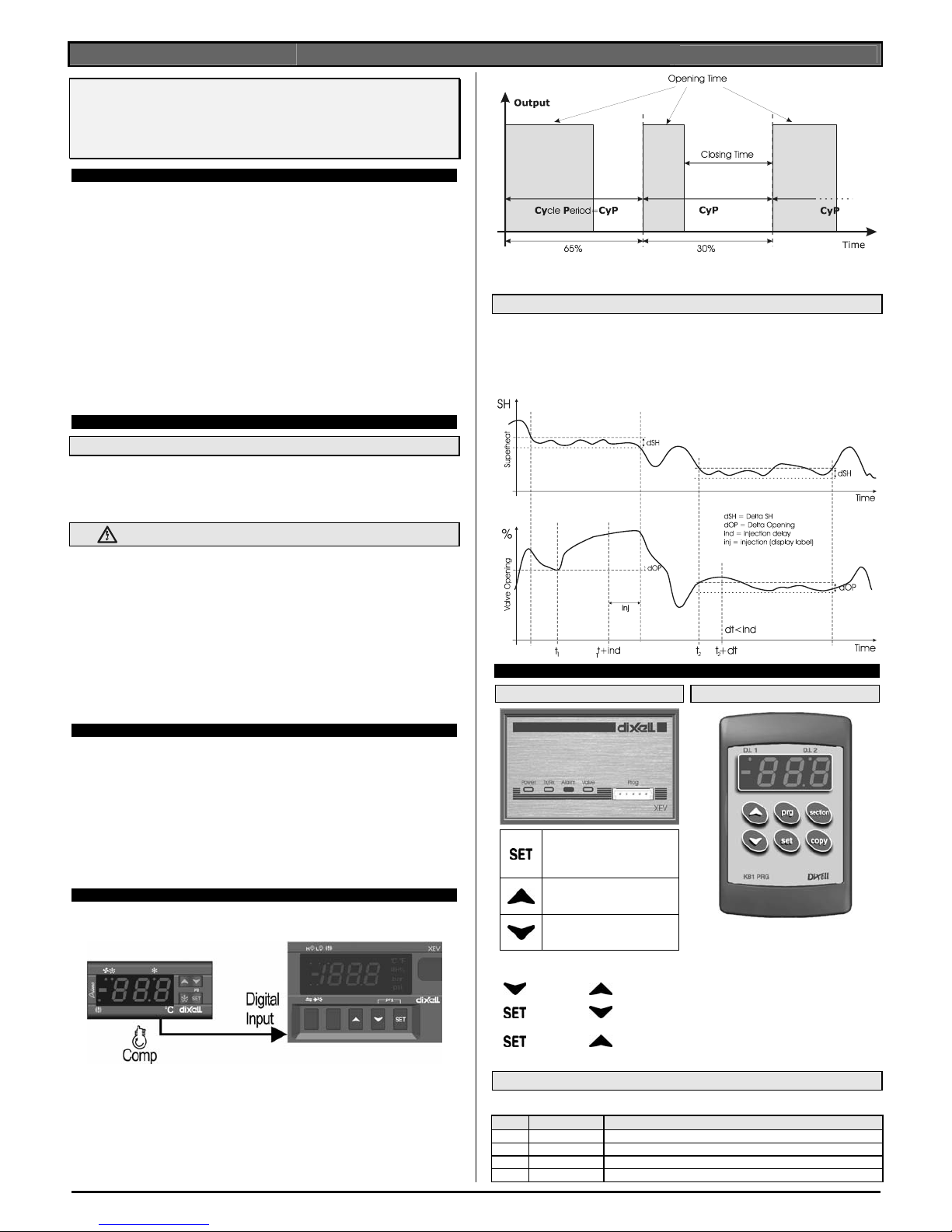
The superheat regulation is performed only when the cooling request is active. The following scheme
shows how device reads the request of cooling:
The regulation is obtained with PI controller that it changes the valve opening percentage. Opening
percentage is obtained from average of Opening Time respect to CyP time period like following
diagram:
With opening percentage we mean percentage of cycle period where valve is open. For example, if
CyP=6s and we say: “The valve opening percentage is 50%”; we mean the valve is opened for 3s
during cycle period.
3.1 INJECTION SIGNALLING
The graph illustrates how to work the function for injection problems signalling. When superheat stays
in dSH (delta SuperHeat) band and valve increases continuously its opening more than dOP (delta
OPening) for ind time (injection delay) the driver signals a gas problem. When this event occurs, the
behaviour of the valve can be fitted to your demand. Trough inb (injection behaviour) parameter you
can choose if the valve have to close completely (inb=cL) , or if regulation have to continue normally
with PI.
1
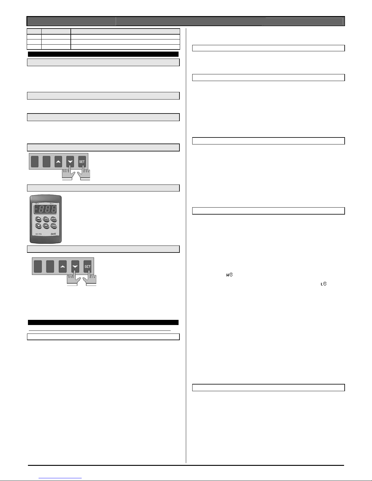
4. FRONT PANEL
XEV11D
To display and to modify the set
point. In programming mode it
selects a parameter or it
confirms a value.
In programming mode it slides
the codes of the parameters or it
increases their values.
In programming mode it slides
the codes of parameters or it
decreases their values.
KB1-PRG
KEYS COMBINATIONS
+
To lock or to unlock the keyboard.
+
To enter to programming mode.
+
Press and hold this keys combination about 5 seconds to activate
valve ON function (described in Plant start section). If you are in
programming mode this combination permits to leave it.
4.1 XEV11D LEDS
XEV11D has four LEDs. Their meaning is described in the following table:
LED MODE Function
POWER
ON The power supply is ok
TX/RX
OFF There is no RS485 activity
TX/RX
BLINKING Serial communication present
VALVE
ON Valve is opened
Page 2
dIXEL
Operating instruction manual
1592019010
1592019010 XEV11D GB r1.2 2008.07.08.doc XEV11D 2/4
LED MODE Function
VALVE
OFF Valve is closed
ALARM
ON Alarm present
ALARM
OFF There is no alarm
5. USER INTERFACE
5.1 TO SEE THE READ-ONLY PARAMETERS
1) Press and release o key;
2) First read-only label is showed;
3) Slide labels with o or narrows;
4) Press SET to see read-only value, to change value to see press SET
5) To leave, press and release o+ SET or wait time-out of about 3 minutes.
5.2 TO SEE THE SET POINT
1) Press the SET key until the set point will be showed;
2) To come back to see temperature, wait about 5s or press newly SET key.
5.3 TO MODIFY THE SET POINT
To change the set point value operate as follows:
1) Press the SET key until the set point will be showed;
2) Use o or n to change its value.
3) Press “SET” to store the new value.
5.4 TO GO TO “PR1” PARAMETERS
To enter in “Pr1” level menu:
1) Pressing SET+ nkeys for about 3 seconds.
2) Instruments shows first parameter in Pr1 menu
5.5 TO GO TO “PR2” PARAMETERS
To enter to “Pr2” parameters list:
1. Enter to “Pr1”
2. Select “Pr2” parameter and press SET
3. The “PAS” label will be shown, then “0 - - “ with 0 blinking.
4. Insert “321” password through o and n keys, then press SET to
confirm.
5.6 TO MODIFY THE PARAMETERS VALUE
To change the parameter’s value operate as
follows:
1. Enter the Programming mode by
pressing the Set and DOWN key for
about 3s.
2. Select the required parameter.
3. Press the “SET” key to display its value
4. Use o or n to change its value.
5. Press “SET” to store the new value and move to the following parameter.
To exit: Press SET + o or wait 30s without pressing a key.
NOTE: the set value is stored even when the procedure is exited by waiting the time-out to expire.
6. PARAMETERS LIST
NOTE: All pressure parameters are relatives or absolutes depending on PrM parameter.
REGULATION
FtY Kind of gas (R22, 134, 404, 407, 410, 507, CO2): Type of gas used by plant.
Fundamental parameter for correct functioning of all system.
PEO Probe Error opening percentage: (0÷100%) if a temporary probe error occurs, valve
opening percentage is PEo until PEd time is elapsed.
PEd Probe Error delay before stopping regulation: (0÷239 sec. – 240=unlimited) if probe
error duration is bigger than PEd then valve totally closes. If PEd=240 valve opening is
PEo until probe error finishes.
ESF Enable Start Function: (n÷Y) n= when digital input configured as CCL is activated, normal
regulation starts immediately; Y= when digital input configured as CCL is activated valve
opens with OPE percentage for time SFd.
OPE Start opening Percentage: (0÷100%) Opening valve percentage when start function is
active and during post defrost phase. This phase duration is SFd time.
SFd Start Function duration: (0.0÷42.0 min: tens of seconds) It sets start function duration
and post-defrost duration. During this phase the alarms are neglected
ind injection delay: (0.0÷42.0 min: tens of seconds) view paragraph 3.1
dSH delta SuperHeat: (0.1÷10°C / 1÷50°F) view paragraph 3.1
dOP delta Opening Percentage: (0÷100%) view paragraph 3.1
inb injection behaviour: (rEG ÷ cL) when an injection problem is signalled if inb=cL valve will
close completely, if inb=rEG valve will regulate normaly by PI (see paragraph 3.1).
Sti Stop regulation interval: (0.0÷24.0 hours: tens of minutes) after regulating
continuously for Sti time, the valve closes for Std time in order to prevent ice creation.
Std Stop duration: (0÷60 min.) it defines stop regulation time after Sti. During this stop display
shows StP message
MnF Maximum opening percentage at normal Functioning: (0÷100%) during regulation it
sets the maximum valve opening percentage.
FOt Forced Opening time-out: (0.0÷24.0 hours: tens of minutes) If Plant starting function is
enabled for all FOt time the function is disabled automatically, see Plant starting function
paragraph.
PI PARAMETERS (trained staff)
CyP Cycle Period: (1 ÷ 15s) it permits to set cycle time.
Pb Proportional band: (0.1 ÷ 50.0 / 1÷90°F) PI proportional band
rS Band Offset: (-12.0 ÷ 12.0°C / -21÷21°F) PI band offset
inC Integration time: (0 ÷ 255s) PI integration time
PROBE PARAMETERS
tPP type of Pressure transducer: (PP – LAn) it sets type of pressure transducer to use: PP=
4÷20mA pressure transducer or ratiometric transducer 0÷5V, LAn= the pressure signal
arrives from another XEV module.
PA4 Probe value At 4mA or At 0V: (-1.0 ÷ P20 bar / -14 ÷ PSI / -10 ÷ P20 kPA*10) pressure
value measured by probe at 4mA or at 0V (related to PrM parameter)
P20 Probe value 20mA or At 5V: (PA4 ÷ 50.0 bar / 725 psi / 500 kPA*10) pressure value
measured by probe at 20mA or at 5V (related to PrM parameter)
oPr Pressure probe calibration: (-12.0 ÷ 12.0 bar / -174÷174 psi / -120 ÷ 120 kPA*10)
ttE type of tEmperature probe: (PtM ÷ Ntc) it allows to set the kind of probe used by the
instrument: PtM = Pt1000, ntC = NTC probe.
otE Temperature probe calibration: (-12.0 ÷ 12.0 °C / -21÷21 °F)
DIGITAL INPUTS
i1P Digital Input 1 (Free of voltage) digital input polarity: (cL,OP) CL= activated when
closed; OP= activated when opened
i1F Digital Input 1 (Free of voltage) digital input function: (CCL, rL, dEF) CCL= cooling
call; rL= digital input activates relay; dEF= digital input signals that defrost is active
d1d Digital Input 1 (Free of voltage) activation delay: (0÷255 min.) this activation delay is
used only if digital input is configured as rL
i2P Digital Input 2 (High voltage) digital input polarity: (CL,OP) CL= activated when closed;
OP=activated when opened
i2F Digital Input 2 (High voltage) digital input function: (CCL, rL, dEF) CCL= cooling call;
rL= digital input activates relay; dEF= digital input signals that defrost is active
d2d Digital Input 2 (High voltage) activation delay: (0÷255 min.) this activation delay is used
only if digital input is configured as rL
ALARM
dAO Alarm delay after restarting regulation: (0.0÷42.0 min: tens of seconds) time between
digital input activation (configured as CCL) and alarm signalling
tdA Type of alarm signalled by relay: (ALL, SH, PrE, di, LOC, inJ) ALL= all alarm; SH=
superheat alarm; PrE= pressure alarm; di= activation only when digital input configured as
rL is actived; LOC= lock alarm in case of nPA events reached; inJ= activation in cases of
injection alarm.
LPL Lower Pressure Limit for superheat regulation: (PA4 ÷ P20 bar / psi / kPA*10) when
suction pressure comes down to LPL the regulation is performed with a LPL fixed value for
pressure, when pressure comes back to LPL the normal pressure value is used. (related to
PrM parameter)
MOP Maximum Operating Pressure threshold: (PA4 ÷ P20 bar / psi / kPA*10) if suction
pressure exceeds maximum operating pressure value, instrument signals situation with
alarm LED
. (related to PrM parameter)
LOP Lowest Operating Pressure: (PA4 ÷ P20 bar / psi / kPA*10) if the suction pressure
comes down to this value a low pressure alarm is signalled with alarm LED
. (related to
PrM parameter)
PHy Pressure alarm Hysteresis: (0.1 ÷ 5.0 bar / 1÷ 72 PSI / 1÷50 kPA*10) alarm hysteresis
to disable alarm signalling.
dML delta MOP-LOP: (0 ÷ 100%) when a MOP alarm occurs valve will close of the dML
percentage every cycle period until MOP alarm is active. When LOP occurs valve will open
of the dML percentage every cycle period until LOP alarm is active.
tPA Maximum time between two MOP and/or LOP events: (0.0÷42.0 min: tens of
seconds) time interval to calculate the number of the pressure switch activation.
nPA Number of events before locking: (0=Off ÷ 100) number of MOP or LOP events, during
the “tPA” interval, before locking instrument.
MSH Maximum SuperHeat alarm: (LSH÷32,0°C / LSH÷176°F) when superheat exceeds this
value an high superheat alarm is signalled after interval SHd
LSH Lowest SuperHeat alarm: (0.0÷MSH °C / 32÷MSH °F) when superheat goes down to this
value a low superheat alarm is signalled after interval SHd
SHy SuperHeat alarm Hysteresis: (0.0÷25.5°C / 1÷77°F) hysteresis for superheat alarm
deactivation
SHd SuperHeat alarm activation delay: (0÷255s) when a superheat alarm occurs, the time
SHd have to pass before signalling alarm
FrC Fast-recovery Constant: (0÷100s) permits to increase integral time when SH is below the
set-point. If FrC=0 fast recovery function is disabled.
DISPLAY
Lod Local display:(SH, PEr, P1, P2) SH= superheat; PEr = valve opening percentage; P1=
value of temperature measured; P2= pressure measured by P2 probe;
CF Temperature measurement units: (°C÷°F) °C= Celsius degree; °F= Fahrenheit degree;
ATTENTION: by changing measurement unit, the regulation parameters have to be
correctly changed
PMu Pressure Measurement units: (bAr, PSI, kPA*10) bAr= bar; PSI= psi; PA= KPa*10;
ATTENTION: by changing measurement unit, the regulation parameters have to be
correctly changed
PrM Pressure visualization Mode: (rEL÷AbS) rEL= relative pressure; AbS= absolute
pressure;
CLt CooLing time statistic: (0÷48h) time interval used to evaluate a cooling call statistic.
During this time comes calculated how much time the cooling call is remained active
CLP CooLing Percentage (read only): Display the percentage of time during which the cooling
call was active in the time interval defined by parameter CLt
tP1 temperature Probe value (read only): it shows temperature probe value from P1
Page 3

dIXEL
Operating instruction manual
1592019010
1592019010 XEV11D GB r1.2 2008.07.08.doc XEV11D 3/4
PPr Pressure probe value (read only): it shows pressure probe value. The value depends on
PrM.
tP2 temperature from P2 (read only): it shows temperature obtained from conversion of
pressure value
d1S Free of voltage digital input State (read only): it shows the free of voltage digital input;
d2S High voltage digital input State (read only): it shows the high voltage digital input state;
Adr RS485 Serial Address: (1÷247) Identifies the instrument address when connected to a
ModBUS compatible monitoring system.
Mod ModBus: (AdU÷StD) AdU= (Only for XWEB3000 system) in this case XEV and
thermostatic controller are considered an alone instrument (it requires a custom library for
XWEB); StD= to use XEV in stand-alone mode, in this case normal Modbus-RTU protocol
is used;
Ptb Parameters map: (read only) it identifies parameters map written by factory
rEL Release Firmware: (read only) it shows firmware release
Pr2 Second level menu
7. DIGITAL INPUTS
There are two digital inputs. One of them is free of voltage and the other is at supply voltage and both
can be configured as cooling call. In this way the cooling call can arrive via instruments with direct load
outputs or via instruments with output without voltage. One of these inputs must be configured as
cooling call.
8. PLANT STARTING FUNCTION
If necessary, by pressing and holding o+ SET keys combination for 5 seconds the driver opens
completely the valve and shows on display the “ON” label. To disable this function press and hold
another time o+ SET keys combination or activate digital input configured as CCL or wait FOt time
out.
9. ELECTRICAL CONNECTIONS
The instrument are provided with screw terminal block to connect cables with a cross section up to 2,5
mm
2
. Heat-resistant cables have to be used. Before connecting cables make sure the power supply
complies with the instrument’s requirements. Separate the probe cables from the power supply cables,
from the outputs and the power connections. Do not exceed the maximum current allowed on each
relay, in case of heavier loads use a suitable external relay.
9.1 PROBES
Advised temperature probe placement is
illustrated in the figure. Between 0 and 180
inclination degrees respect to horizontal pipe
section. For suction pressure probe there
aren’t particular prescriptions
10. RS485 SERIAL LINE
All models can be connected to the monitoring and supervising system XWEB3000. If Mod=Std
standard ModBUS-RTU protocol is used, if Mod=AdU custom XWEB library is required.
11. HOW TO USE THE HOT KEY
11.1 HOW TO PROGRAM A HOT KEY FROM THE INSTRUMENT (UPLOAD)
1. Program one controller with the remote keypad;
2. When the controller is ON
, insert the “Hot key”; the four LEDs in the front of instrument panel
blink for about 5 seconds to indicate that transfer operation will start;
3. The upload starts automatically and Alarm and Tx/Rx LEDs are active during operation;
4. At the end, the instrument turn ON for about 10 seconds:
• the Tx/Rx LED if the operation is well done;
• the Alarm LED if the operation is wrong.
11.2 HOW TO PROGRAM AN INSTRUMENT USING A HOT KEY (DOWNLOAD)
6) Turn OFF the instrument.
7) Insert a programmed “Hot Key” into the 5 PIN connector and then turn the Controller ON.
8) Automatically the download starts and the LEDs Alarm e Tx/Rx are active during operation.
9) At the end, the instrument turn ON for about 10 seconds:
• the Tx/Rx LED if the operation is well done;
• the Alarm LED if the operation is wrong.
NOTE the message “Err” is displayed for failed programming. In this case turn the unit off and then on
if you want to restart the download again or remove the “Hot key” to abort the operation.
12. DISPLAY MESSAGES
Mess. Cause Outputs
“OFF”
None of digital inputs configured as CCL are
activated
Valve closed
“ON” Plant start function is activated Valve opened
“P1” Temperature probe fault according to PEo and PEd
“P2” Pressure transducer fault according to PEo and PEd
“HSH” High superheat alarm By PI
“LSH” Low superheat alarm Valve Closed
“LPL” Low pressure limit see LPL parameter
“MOP” Maximum Operating Pressure see dML parameter
“LOP” Lowest Operating Pressure see dML parameter
“StF” Start Function enabled see ESF parameter
“StP” Regulation stop caused by Std and Sti Valve closed
“dEF” Defrost in progress Valve closed
“EE” Memory anomaly
12.1 ALARM RECOVERY
Probe alarms “P1”, “P2” start few seconds after the fault in the probe; they automatically stop few
seconds after the probe restarts normal operation. Check connections before replacing the probe.
Max. and min. alarms “HSH” “LSH” “MOP” “LOP” automatically stop as soon as the variable returns to
normal values.
12.2 ALARM “EE”
The instrument is provided with an internal check verifying memory integrity. Alarm “EE” flashes when
a failure in the internal memory is detected. In such case call the service.
13. TECHNICAL DATA
Housing: self extinguishing ABS.
Case: 4 DIN modules 70x85 mm; depth 61mm
Mounting: DIN RAIL mounted in a omega (3) din rail
Protection: IP20.
Connections: Screw terminal block ≤ 2,5 mm
2
wiring.
Power supply: 24Vac ±10%; 110Vac ±10%; 230Vac ±10% 50/60Hz 50/60Hz
Power absorption: 6VA max
Display: three digits with icons, red LEDs, height 14,2 mm.
Inputs: 1 temperature probe Pt1000 or NTC;
1 pressure transducer 4÷20mA o 0÷5V;
Digital inputs: 1 free of voltage
1 at Main voltage
Outputs for valve: 30W max
Data storage: on the non-volatile memory (EEPROM).
Kind of action: 1B; Pollution grade: normal; Software Class: A
Operating temperature: 0÷60°C; Storage temperature: -25÷60 °C.
Relative humidity: 20÷85% (no condensing)
Resolution: 0,1 °C or 1 °F; Precision a 25°C:: ±0,7 °C ±1 digit
14. WIRING CONNECTIONS
24-110Vac Models: Power supply, high voltage digital input and valve output are respectively 24Vac
or 110Vac.
15. STANDARD VALUES
Label Description Range Default Level
FtY
Kind of gas
R22 , 134 , 404, 407,
410, 507, CO2
404 Pr2
PEo
Probe Error opening percentage 0 ÷ 100 % 50 Pr2
PEd
Probe Error delay before stopping
regulation
0 ÷ 239 s - On On Pr2
ESF
Enable Start Function n ÷ Y Y Pr2
OPE
Start opening Percentage 0 ÷ 100 % 85 Pr2
SFd
Start Function duration
0.0÷42.0 minutes: tens
of seconds
1.3
Pr2
ind
injection delay
0.0÷42.0 minutes: tens
of seconds
10.0
Pr2
dSH
delta SuperHeat 0.1 ÷ 10°C / 1÷50°F 0.1 Pr2
dOP
delta Opening Percentage 0 ÷ 100 % 100 Pr2
inb
injection behaviour cL ÷ rEG rEG Pr2
Sti
Stop regulation interval
0.0÷24.0 hours: tens of
minutes
1.3
Pr2
Std
Stop duration 0 ÷ 60 min. 3 Pr2
MnF
Maximum opening percentage 0 ÷ 100 % 100 Pr2
FOt
Forced Opening time-out
0.0÷24.0 hours: tens of
minutes
0.1 Pr2
Page 4

dIXEL
Operating instruction manual
1592019010
1592019010 XEV11D GB r1.2 2008.07.08.doc XEV11D 4/4
PI PARAMETERS (trained staff)
CyP
Cycle Period 1 ÷ 15 s 6 Pr1
Pb
Proportional band 0.1 ÷ 50.0 °C / 1÷90 °F 4.0 Pr2
rS
Band Offset
-12.0 ÷ 12.0 °C / -21 ÷
21°F
0.0 Pr2
inC
Integration time 0 ÷ 255 s 120 Pr2
PROBE PARAMETERS
tPP
Type of pressure transducer PP - LAn PP Pr2
PA4
Probe value at 4mA or at 0V (related to
PrM parameter)
-1.0 bar / -14 PSI / -10
kPA*10 ÷ P20
-0.5 Pr2
P20
Probe value at 20mA or at 5V (related
to PrM parameter)
PA4 ÷ 50.0 bar / 725
PSI / 500 kPA*10
11.0 Pr2
oPr
Pressure probe calibration
-12.0 ÷ 12.0 bar / -174 ÷
174 psi / -120 ÷ 120
kPA*10
0 Pr2
ttE
type of tEmperature probe PtM ÷ ntc PtM Pr2
otE
Temperature probe calibration
-12.0 ÷ 12.0 °C / -21 ÷
21 °F
0 Pr2
DIGITAL INPUTS
i1P
Free of voltage digital input polarity cL – OP CL Pr2
i1F
Free of voltage digital input function CCL , rL, dEF CCL Pr2
d1d
Digital input 1 (free of voltage)
activation delay
0 ÷ 255 min. 0 Pr2
i2P
Main voltage digital input polarity cL – OP CL Pr2
i2F
Main voltage digital input function CCL , rL, dEF CCL Pr2
d2d
Digital input 2 (Main voltage) activation
delay
0 ÷ 255min. 0 Pr2
ALARMS
dAO
Alarm delay after restarting regulation
0.0÷42.0 hours: tens of
seconds
3.3
Pr2
tdA
Type of alarm signalled by relay
ALL, SH, PrE, DI, LOC,
inJ
ALL Pr2
LPL
Lower pressure limit for superheat
regulation (related to PrM parameter)
PA4 ÷ P20 bar / PSI /
kPA*10
-0.5 Pr2
MOP
Maximum operating pressure threshold
(related to PrM parameter)
PA4 ÷ P20 bar / PSI /
kPA*10
11.0 Pr2
LOP
Minimum suction pressure limit (related
to PrM parameter)
PA4 ÷ P20 bar / PSI /
kPA*10
-0.5 Pr2
PHy
Pressure alarm Hysteresis
0.1 ÷ 5.0 bar / 1÷ 72 psi
/ 1÷50 kPA*10
0.1 Pr2
dML
delta MOP-LOP 0 ÷ 100% 30 Pr2
tPA
Maximum time between two MOP
and/or LOP events
0.0÷42.0 hours: tens of
seconds
0.1
Pr2
nPA
Number of events before locking 0(Off) ÷ 100 0 Pr2
MSH
Maximum superheat alarm
LSH ÷ 32.0 °C / LSH ÷
176 °F
50.0 Pr1
LSH
Lowest superheat alarm
0.0 ÷ MSH °C / 32 ÷
MSH °F
2.5 Pr1
SHy
Superheat hysteresis 0.1 ÷ 25.5 °C / 1 ÷ 77°F 0.5 Pr2
SHd
Superheat alarm activation delay 0 ÷ 255 s 10 Pr1
FrC
Fast-Recovery Constant 0÷100 s 50 Pr2
DISPLAY
Lod
Local display SH - PEr – P1 - P2 SH Pr1
CF
Temperature measurement units °C - °F °C Pr2
PMu
Pressure measurement unit bAr – PSI – PA bAr Pr2
PrM
Type of pressure (Absolute / relative) rEL – AbS rEL Pr2
CLt
Time to evaluate Cooling statistic 0 ÷ 48 hours 48 Pr1
CLP
Cooling call percentage
Read only
- - - Pr2
tP1
Temperature probe value Read only - -- Pr1
PPr
Pressure probe value
Read only
- - - Pr1
tP2
Temperature converted from pressure
probe
Read only
- - - Pr1
d1S
Free of voltage digital input state
Read only
- - - Pr1
d2S
Main voltage digital input state
Read only
- - - Pr1
Adr
Serial address 1÷247 1 Pr2
Mod
Modbus type Std – AdU StD Pr2
Ptb
Parameters map - - - - - - Pr2
rEL
Release software - - - - - - Pr2
Pr2
Second level menu - - - - - - Pr1
16. EXAMPLE OF APPLICATION
dIXEL S.p.a.
Z.I. Via dell’Industria, 27 - 32010 Pieve d’Alpago (BL) ITALY
tel. +39 - 0437 - 98 33 - fax +39 - 0437 - 98 93 13
http://www.dixell.com
E-mail: dixell@dixell.com
 Loading...