

Page 1
Dixell
Installing and Operating Instructions
rel.1.0 –25/10/2000 - cod. 1592009540
1592009540 XW272K_full GB XW272K 1/5
WING
XW272K
1. GENERAL WARNING
1.1 PLEASE READ BEFORE USING THIS MANUAL
• This manual is part of the product and should be kept near the instrument for easy and quick
reference.
• The instrument shall not be used for purposes differe nt from those descri bed hereunder. I t cannot be
used as a safety device.
• Check the application limits before proceeding.
1.2
SAFETY PRECAUTIONS
• Check the supply voltage is correct before conn ecting the instrument.
• Do not expose to water or moisture: use the control ler only withi n the oper ating limi ts avoiding s udden
temperature changes with high atmospheric humidity to prevent formation of condensation
• Warning: disconnect all electrical connections before any kind of maintenance.
• Fit the probe where it is not accessible by the End User. The instrument must not be opened.
• In case of failure or faulty operation send the instrument back to the distributor or to “Dixell s.r.l.” (see
address) with a detailed description of the f ault.
• Consider the maximum current which can be applied to each relay (see Technical Data).
• Ensure that the wires for probes, loads a nd th e pow er suppl y ar e separat ed and far enoug h from ea ch
other, without crossing or intertwining.
• In case of applications in industrial environments, the use of mains filters (our mod. FT1) in parallel
with inductive loads could be useful.
2. GENERAL DESCRIPTION
Model XW272K is microprocessor ba sed controller suitabl e for application s on medium or low tem perature
refrigerating units. It must be connected by mean s of a two-wire cable (∅ 1mm) at a distance of u p to 30
meters to the keyboard T620. It is provided with six relay outputs to control two compressors, defrost - which
can be either electrical or hot gas - the evaporat or fans, the lights and the alarm. It i s also provided with
three NTC probe inputs, one for temp erature control, one to control the defrost e nd temperature of the
evaporator and the third, optional, for the display. There are two digital inputs (free contact) for the door
switch and configurable by parameter.
The standard TTL output allows the user to connect, by means of a TTL/RS485 external module, a
ModBUS-RTU compatible monitoring system and to programme the parameter list with the “Hot Key”. A
4÷20 mA output to control ev aporat or or conden ser f ans an d th e dire ct seri al out put RS485 are av ailable as
options.
3. CONTROLLING LOADS
3.1 THE COMPRESSOR
The regulation is performed according to the temperature measured by the thermostat probe with a positive
differential from the set point: if the temperature increases and reaches set point plus differential the
compressor is started and then turned off whe n the temperature reaches the set point value again.
In case of fault in the thermostat probe the start and st op of the compressor are timed t hrough parameters
“COn” and “COF”.
3.2 SECOND COMPRESSOR
The second compressor is switched ON after a delay (AC1) of the first compressor activation. Compressors
can be switched ON always with the same sequence or in an alternate way.
CCO = Se : The first compressor is always switched on before the second one.
CCO = Al : The compressors are switched on in an alternate way.
3.3 FAST FREEZING
When defrost is not in progress, it can be acti vated the keypad by holding the è key pressed for about 3
seconds. The compressor operates in continuo us mode for the time set through the “ CCt” parameter. The
cycle can be terminated before the end of the set time using the same activation key, è for about 3
seconds.
3.4 DEFROST
Three defrost modes are available through the “ tdF” parameter: defrost with electrical heater, hot gas or
thermostatic defrost. The defrost int erval is control by means of parameter “EdF”: (EdF=in) the defrost is
made every “IdF” time, (EdF=Sd) the interval “IdF” is calculate through Smart Defrost algorithm (only when
the compressor is ON and the evaporator temp erature is bigger than “SdF” parameter).
At the end of defrost the drip time is controlled thr ough the “Fdt” parameter.
3.5 CONTROL OF EVAPORATOR FANS
The fan control mode is selected by means of the “ FnC” parameter:
C-n = running with the compressor, OFF during the defrost;
C-y = running with the compressor, ON during the defrost;
O-n = continuous mode, OFF during the defrost;
O-y = continuous mode, ON during the defrost;
An additional parameter “FSt” provides the setting of temperat ure, detected by t he evaporator pro be, above
which the fans are always OFF. This can be use d to make sure circulation of air only if his temperature is
lower than set in “FSt”.
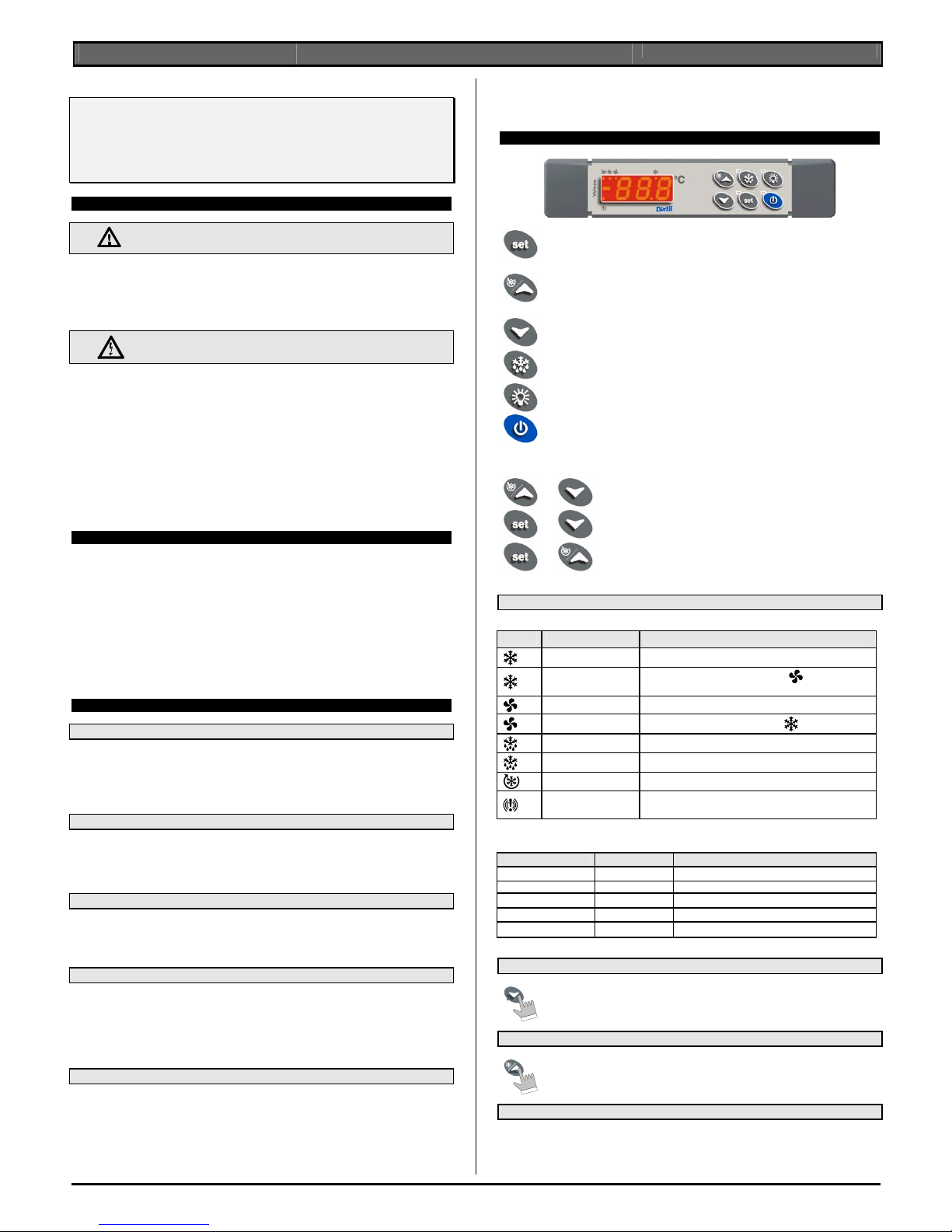
4. KEYBOARD
To display and modify target set point; in progra mming mode it selects a parameter or
confirm an operation.
By holding it pressed for 3s when max or min temperature is displayed it will be erased.
To see the max. stored temperature; in program ming mode it browses the parameter
codes or increases the displayed value.
By holding it pressed for 3s the fast freezing cycle is started.
To see the min stored temperature; in program ming mode it browses the parameter
codes or decreases the displayed value.
By holding it pressed for 3s the defrost i s started.
Switch ON and OFF the cold room light.
Switch ON and OFF the instrument.
KEY COMBINATIONS
+
To lock and unlock the keyboard.
+
To enter the programming mode.
+
To exit the programming mode.
4.1 USE OF LEDS
Each LED function is described in the following ta bl e.
LED MODE FUNCTION
ON The compressor is running
FLASHING
- Programming Phase (flashing with LED
)
- Anti-short cycle delay enabled
ON The fan is running
FLASHING
Programming Phase (flashing with LED
)
ON The defrost is enabled
FLASHING Drip time in progress
ON The Fast Freezing cycle is enabled
ON
- ALARM signal
- In “Pr2” indicates that the parameter is als o present in “Pr1”
Function of the LEDs placed on the left top side of buttons:
BUTTON MODE FUNCTION
SET FLASHING The Set point is displayed and it can be modified
SET FAST FLASHING The Energy Saving is enabled
DEFROST ON The Manual Defrost is activated
LIGHT ON The Light is ON
ON/OFF ON The instrument is OFF
4.2 HOW TO SEE THE MIN TEMPERATURE
1.
Press and release the à key.
2.
The “Lo” message will be displayed followed by the minimum temperature recorded.
3.
By pressing the à key or waiting for 5s the normal display will be restored.
4.3 HOW TO SEE THE MAX TEMPERATURE
1.
Press and release the è key.
2. The “Hi” message will be displayed followed by the maximum temperature recorded.
3.
By pressing the è key or waiting for 5s the normal display will be restored.
4.4 HOW TO RESET THE MAX AND MIN TEMPERATURE RECORDED
To reset the stored temperature, when max or min temperature is displayed :
1. Press SET key until “rST” label starts blinking.
N.B. After the installation RESET the temperature stored .
Page 2
Dixell
Installing and Operating Instructions
rel.1.0 –25/10/2000 - cod. 1592009540
1592009540 XW272K_full GB XW272K 2/5
4.5 HOW TO SEE AND MODIFY THE SET POINT
1. Push and immediately release the SET key: the display will show the Set point value;
2. The SET LED start blinking;
3. To change the Set value push the è or à arrows within 10s.
4. To memorise the new set point value push the SET key again or wait 10s.
4.6 TO START A MANUAL DEFROST
1. Push the DEF key for more than 2 seconds and a manual defrost will start.
4.7 TO ENTER IN PARAMETERS LIST “PR1”
To enter the parameter list “Pr1” (user accessible parameters) operate as follows:
1. Enter the Programming mode by pressing the Set and DOWN ke y
for few seconds (
and
start blinking).
2. The instrument will show the first parameter present in “Pr1”
4.8 TO ENTER IN PARAMETERS LIST “PR2”
To access parameters in “Pr2”:
1. Enter the “Pr1” level.
2. Select “Pr2” parameter and press t he “SET” key.
3. The “PAS” flashing message is displayed, shortly followed by “0 - -” with a flashing zero.
4. Use è or à to input the security code in the flashing digit; confirm the figure by pressing “SET”. The
security code is “321“.
5. If the security code is correct the access to “Pr2” is enabled by pressing “SET” on the last digit.
Another possibility is the following: after switching ON the instrument the user can push Set and DOWN keys
within 30 seconds.
NOTE: each parameter in “Pr2” can be removed or put i nto “P r1 ” ( user l ev el) by pres si ng “SET” + à. When
a parameter is present in “Pr1” LED
is on.
4.9 HOW TO CHANGE THE PARAMETER VALUE
1. Enter the Programming mode.
2. Select the required parameter with è or à.
3. Press the “SET” key to display its value (
and LED starts blinking).
4. Use è or à to change its value.
5. Press “SET” to store the new value and move to the following parameter.
To exit: Press SET + UP or wait 15s without pressing a key.
NOTE: the new programming is stored even when the procedure is exited by waiting the time-out.
4.10 HOW TO LOCK THE KEYBOARD
1.
Keep the è and à keys pressed together for more than 3 s the è and à keys.
2.
The “POF” message will be displayed and the keyboard is locked. At this point it is
only possible the viewing of the set point or th e MAX o Min temperature st ored and
to switch ON and OFF the light, the auxiliary output and the instrument.
TO UNLOCK THE KEYBOARD
Keep the è and à keys pressed together for more than 3s.
4.11 ON/OFF FUNCTION
By pushing the ON/OFF key, the instrument show s “OFF” fo r 5 sec. and t he ON/OFF LE D
is switched ON.
During the OFF status, all the relays are switc hed OFF and the reg ulations are st opped; if
a monitoring system is connected, it does not record the instrument data and alarms.
N.B. During the OFF status the Light and AUX buttons are active.
4.12 TO SEE THE PROBE VALUES
1.
Enter in “Pr2” level.
2.
Select “Prd” parameter with è or à.
3.
Press the “SET” key to display “Pb1” label alternate with Pb1 value.
4.
Use è and à keys to display the other probe values.
5.
Press “SET” to move to the following parameter.
5. PARAMETER LIST
REGULATION
Hy Differential: (0,1÷25,5°C; 1÷45°F): Intervention differential for set point, always positive. Compressor
Cut IN is Set Point Plus Differential (Hy). Compressor Cut OUT is when the temperature reaches the
set point.
LS Minimum set point limit: (-50,0°C
÷SET; -58°F÷SET) Sets the minimum acceptable value for t he set
point.
US Maximum set point limit: (SET
÷110°C; SET÷230°F) Set the maximum acceptable value for set
point.
OdS Outputs activation delay at start up: (0÷255 min) This function i s ena bled at the ini ti al st art up of t h e
instrument and inhibits any output activation for the period of time set in the parameter. (AUX and Light
can work)
CCO Compressors configuration : (Se,Al)
Se : The first compressor is always switched on before the second one.
Al : The compressors are switched on in an alternate way.
AC Anti-short cycle delay: (0÷30 min) interval between the compressor stop and the following restart.
AC1 Time delay between turning on compressor 1 and 2 : (0÷255 sec) allows to set the delay between
turning on the first and the second compressor.
CCt Thermostat override: (0min ÷23h 50min) allows to set the length of the continuou s cycle. Can be
used, for instance, when the room is filled with new products.
Con Compressor ON time with faulty probe: (0÷255 min) time duri ng which the compressor is active in
case of faulty thermostat probe. With COn=0 compressor is always OFF.
COF Compressor OFF time with faulty probe: (0÷255 min) time during which the compressor is off in
case of faulty thermostat probe. With COF=0 compressor is always active.
DISPLAY
CF Temperature measu rement unit: °C = Celsius; °F = Fahrenheit . When the measurement unit is
changed the SET point and the values of the regulation parameters have to be modified
rES Resolution (for °C): (in = 1°C; de = 0,1°C) allows decimal point display.
de = 0,1°C; in = 1 °C
Red Remote display : select which probe is displayed by the remote display (T620)
P1 = Thermostat probe; P2 = Evaporator probe; P3 = auxiliary probe;
1r2 = difference between P1 and P2 (P1-P2)
DEFROST
tdF Defrost type:
rE = electrical heater (Compressor OFF)
rT = thermostat defrost. During the defrost time “MdF”, the heater switches On and OFF depending on
the evaporator temperature and “dtE” value.
in = hot gas (Compressor and defrost relays ON)
EdF Defrost mode:
in = interval mode. The defrost starts when the time “Idf” is expired.
Sd = Smartfrost mode. The time IdF (interval between defrosts) is increased only when the
compressor is running (even non consecut ively ) a nd onl y if the evap orat or t empe ratu re is le ss t han t he
value in "SdF” (set point for SMARTFROST).
SdF Set point for SMARTFROST: (-30
÷30 °C/ -22÷86 °F) evaporator tempe rature which allows the I dF
counting (interval between defrosts) in SMARTFROST mode.
dtE Defrost termination temperature: (-50,0÷110,0°C; -58÷230°F) (Enabled only when the evaporator
probe is present) sets the temperatur e measured by the evaporator probe which causes the end of
defrost.
IdF Interval between defrosts: (1÷120h) Determines the time interval b etween the beginning of two
defrost cycles.
MdF (Maximum) duration of defrost: (0÷255 min) When P2P = n, no evaporator probe, it sets the defrost
duration, when P2P = y, defrost end based on temperat ure, it sets the maximum length for defrost.
dFd Display during defrost:
rt = real temperature; it = temperature reading at t he defrost start ; Set = set point; dEF = “dEF” label;
dEG = “dEG” label;
dAd Defrost display time out: (0
÷255 min) Sets the maximum time between the end of defrost and the
restarting of the real room temperature displ ay.
Fdt Drain down time: (0÷60 min.) time interval between reaching defrost termin ation temperature and the
restoring of the control’s normal op eration. This time allows the evapo rator to eliminate water drops
that might have formed due to defrost.
dPO First defrost after start-up:
y = Immediately; n = after the IdF time
dAF Defrost delay afte r fast freezin g: (0min÷23h 50 min) aft er a Fast F reezing cy cle, the f irst defr ost wil l
be delayed for this time.
FANS
FnC Fan operating mode:
C-n = running with the compressor, OFF during the defrost;
C-y = running with the compressor, ON during the defrost;
O-n = continuous mode, OFF during the defrost;
O-y = continuous mode, ON during the defrost;
Fnd Fan delay after defrost: (0÷255 min) The time interval between t he defrost end and evaporat or fans
start.
FSt Fan stop temperature: (-50÷110°C; -58÷230°F) setting of temperature, detected by evaporator
probe, above which the fan is always OFF.
ALARMS
ALC Temperature alarm configuration
rE = High and Low alarms related to Set Point
Ab = High and low alarms related to the absolute temperature.
ALU High temperature alarm setting:
ALC= rE, 0
÷ 50°C or 90°F
ALC= Ab, ALL
÷ 110°C or 230°F
when this temperature is reached and after the AL d delay time the HA alarm is enabled.
ALL Low temperature alarm setting:
ALC = rE , 0
÷ 50 °C or 90°F
ALC = Ab , - 50°C or -58°F
÷ ALU
when this temperature is reached and after the AL d delay time, the LA alarm is enabled,.
AFH Temperature alarm and fan differential: (0,1÷25,5°C; 1÷45°F) Intervention differential for
temperature alarm set point and fan regulation set point, always positive.
ALd Temperature alarm delay: (0÷255 min) time interval between the detection of an alarm condition and
the corresponding alarm signalling.
dAO Delay of temperature alarm at start-up: (0min÷23h 50min) time interval between the detection of the
temperature alarm condition after the instrum ent power on and the alarm signalling.
EdA Alarm delay at the end of defrost: (0
÷255 min) Time interval between the detection of the
temperature alarm condition at the end of defrost and the alarm signalling.
dot Delay of temperature alarm after closing the door : (0
÷255 min) Time delay to signal the
temperature alarm condition after closing the door.
doA Open door alarm delay:(0÷254min,nu) delay bet ween the detection of the open door conditi on and its
alarm signalling: the flashing message “dA” is displayed. If doA=nu the door alarm will be not
signalled.
nPS Pressure switch number: (0
÷15) Number of activation of the pressure switch, during the “did”
interval, before signalling the alarm event (I2F= PAL).
ANALOGUE OUTPUT 4÷20 mA (OPTIONAL)
Page 3

Dixell
Installing and Operating Instructions
rel.1.0 –25/10/2000 - cod. 1592009540
1592009540 XW272K_full GB XW272K 3/5
AOS Analogue output start point: (-50÷110°C or -58°÷230°F). Sets the temperature at which the
analogue output begins.
APB Analogue output band width: (-50 ÷110°C or -58°÷230 °F) sets the width of the regulation band for
the analogue output. If APb is positive then it is above the start point and t he kind of action is direct
(condenser application). If APb is negative then it is below the start point and the kind of action is
inverse (evaporator application).
CAO Input type for the analogue output: four input types can be selected:
P1=room probe temperature; P2 = evaporator probe temperature; P3=temperature of the third probe;
1r2= temperature difference between the room pr obe and the evaporator probe
PROBE INPUTS
Ot Thermostat probe calibration: (-12.0
÷12.0°C/ -21÷21°F) allows to adjust possible offset of the
thermostat probe.
OE Evaporator probe calibration: (-12.0
÷12.0°C/ -21÷21°F) allows to adjust possible offsets of the
evaporator probe.
O3 Auxiliary probe calibration: (-12.0
÷12.0°C/ -21÷21°F) allows to adjust possible offsets of the
evaporator probe.
P2P Evaporator pr obe presence:
n= not present: the defrost stops only by time; y= present: the defrost stops by temperature and time.
P3P Auxiliary probe presence: n= not present; y= present.
HES Temperatu re increase during the Energy S aving cycle : (-30,0°C
÷ 30,0°C / -22÷86°F) sets the
increasing value of the set point during t he Energy Saving cycle.
DIGITAL INPUTS
odc Compressor and fan status when open door :
no = normal; Fan = Fan OFF; CPr = Compressor OFF; F_C = Compressor and fan OFF.
I1P Door switch input polarity:
CL : the digital input is activated by closing the contact;
OP : the digital input is activated by opening the contact.
I2P Configurable digital input polarity:
CL : the digital input is activated by closing the contact;
OP : the digital input is activated by opening the contact
I2F Digital input operating mode: configure the digital input function:
EAL = generic alarm; bAL = serious alarm mode; PAL = Pressure switch;
dFr = Start defrost; AUS = Not used; Es = Energy Saving; onF = remote On/OFF.
did Time interval/delay for digital input alarm:(0
÷255 min.) Time interval to calculate the num ber of th e
pressure switch activation when I2F=PAL. If I2F=EAL or bAL (external alarms), “did” parameter defines
the time delay between the detection and the successive signalling of the alarm.
OTHER
Adr RS485 serial address (1÷247): Identifies the instrument address when connected to a ModBUS
compatible monitoring system.
Rel Release software: (read only) Software ve rsion of the microprocessor.
Ptb Parameter table: (read only) it shows the original code of the dIXEL parameter map.
Prd Probes display: (read only) display the temperature values of the evaporator probe Pb2 and the
auxiliary probe Pb3.
Pr2 Access to the protected parameter list (read only).
6. DIGITAL INPUTS
The Wing series can support up to 2 free contact digital inputs. One is always configured as door switch, the
second is programmable in seven different configurations by the “I2F” parameter.
6.1 DOOR SWITCH INPUT
It signals the door status and the corresp o nding relay output status through the “odc” param eter:
no = normal (any change);
Fan = Fan OFF;
CPr = Compressor OFF;
F_C = Compressor and fan OFF.
Since the door is opened, after the del ay t ime set through parameter “dOA”, the al arm out put i s enabl ed and
the display shows the message “dA”. T he ala rm st ops as soo n a s th e ext e rnal digit al i nput i s di sabl e d a gain.
During this time and then for the delay “dot” after closing the door, the high and low temperature alarms are
disabled.
6.2 CONFIGURABLE INPUT - GENERIC ALARM (EAL)
As soon as the digital input is activated the unit will wait for “did” time delay before signalling the “EAL” alarm
message. The outputs status don’t change. Th e alarm stops just after the digital input is de-act ivated.
6.3 CONFIGURABLE INPUT - SERIOUS ALARM MODE (BAL)
When the digital input is activated, the unit wil l wait for “did” delay before signalling the “BAL” alarm
message. The relay outputs are switched OFF. The alarm will stop as soon as the digital input is deactivated.
6.4 CONFIGURABLE INPUT - PRESSURE SWITCH (PAL)
If during the interval time set by “did” parameter, the pressure switch has reached the number of activation of
the “nPS” parameter, the “PAL” pressure alarm message will be displayed. The compressor and the
regulation are stopped. When the digital input i s ON the compressor is always OFF.
6.5 CONFIGURABLE INPUT - START DEFROST (DFR)
It executes a defrost if there are the right conditions. After the defrost is finished, the normal regulation will
restart only if the digital input is disabled otherwise the instrument will wait until the “Mdf” safety time is
expired.
6.6 CONFIGURABLE INPUT - ENERGY SAVING (ES)
The Energy Saving function allows to change the set poi nt value as the result of the SET+ HES (parmeter)
sum. This function is enabled until the digital input is activated.
6.7 CONFIGURABLE INPUT - REMOTE ON/OFF (ONF)
This function allows to switch ON and OFF the instrument.
6.8 DIGITAL INPUTS POLARITY
The digital inputs polarity depends on “I1P” and “I2P” pa rameters.
CL : the digital input is activated by closing the c ontact.
OP : the digital input is activated by opening the contact
7. ANALOGUE OUTPUT 4÷20 mA (OPTIONAL)
The analogue output is obtained throug h a 4÷20mA signal proportional to the input selected in parameter
“CAO”. Through the analogue output the speed of fans can be regulated according to the i nput variable.
The following input types can be selected th rough the “CAO” parameter:
“CAO” = P1 room temperature
“CAO” = P2 evaporator temperature
“CAO” = P3 third probe t emperature
“CAO” = 1r2 room temperature - evaporator temperature
To adjust the analogue output the following par ameters are available:
“AOS” = Start point for analogue output
“APb” = Band width for analogue output can be either p ositive (direct action) and negative
(inverse action).
Named T the input, the relationship input-output is given by the following charts
NOTE: When the defrost is in progress, the ana logue output is set to the minimum value (4 mA). This
condition lasts until the defrost terminates.
8. INSTALLATION AND MOUNTING
T620 keyboard shall be mounted on vertical panel, in a 150x3 1 mm hole, and fixed u sing two screw s
∅ 3 x
2mm. To obtain an IP65 protection grade use the front panel rubber gasket (mod. RG-L). Power module
XW272K shall be mounted in a panel with two or more screw s and it must be connecte d to the key board by
means of a two-wire cable (∅ 1mm). The tem perature range allowed for correct operation is 0 - 60 °C. Avoid
places subject to strong vibrations, corro sive gases, exces sive dirt or humidi ty. The same re commendations
apply to probes. Let the air circulate by the cooling holes.
8.1 T620 CUT OUT
165
150
31
+0.5
-0
+0.5
-0
+1
-1
Ø3 x2
8.2 MOUNTING WITH KEYBOARD COVER OPENING DOWNWARD
Page 4

Dixell
Installing and Operating Instructions
rel.1.0 –25/10/2000 - cod. 1592009540
1592009540 XW272K_full GB XW272K 4/5
CLICK!
1
2
2
3
3
1
1
8.3 MOUNTING WITH KEYBOARD COVER OPENING UPWARD
CLICK!
1
2
2
2
3
3
1
1
9. ELECTRICAL CONNECTIONS
XW272K is provided with screw terminal blocks t o connect c ables with a c ross section u p to 2,5 mm
2
for the
RS485(optional) and the keyboard. Connecting ot her inputs, power supply and relays, XW272K is p rovided
with Faston connections (6,3mm). Heat-resi stant cables have to be used. Before conn ecting cables make
sure the power supply complies with t he instrument’s requirements. Separate th e probe cables from the
power supply cables, from the output s and the power connections. Do not exceed t he maximum current
allowed on each relay, in case of heavier loads use a suitable external relay.
N.B. Maximum current allowed for all the loads is 20A.
9.1 PROBE CONNECTIONS
The probes shall be mounted with the bulb upwards t o prevent damages d ue to casual l iquid infi ltrati on. It is
recommended to place the thermostat probe away from air streams to correctly measure the average room
temperature. Place the defrost terminatio n pro be a mong th e e vapor ato r fi ns i n the c olde st pl ace, whe re most
ice is formed, far from heaters or from the warmest place during defrost, to prevent prematur e defrost
termination.
10. TTL/RS485 SERIAL LINE
The TTL connector allows, by means of the exter nal module TTL/RS485 (XJ485), to connect the unit to a
network line ModBUS-RTU compatible as the dIXEL monitoring system XJ500 (Version 3.0).
The same TTL connector is used to upload a nd download the parameter list of the “HOT KEY“. The
instruments can be ordered wit the serial output RS485(Optional).
11. USE OF THE PROGRAMMING “HOT KEY”
The Wing units can UPLOAD or DOWNLOAD the parameter list from its own E2 internal memory to the “Hot
Key” and vice-versa.
11.1 DOWNLOAD (FROM THE “HOT KEY” TO THE INSTRUMENT)
1. Turn OFF the instrume nt by means of the ON/O FF key, remo ve t he TT L se ri al cabl e i f pre se nt, i nse rt
the “Hot Key” and then turn the Wing ON.
2. Automatically the parameter list of the “Hot Key” is downloaded into the Wing memory, the “DoL”
message is blinking. After 10 seconds the instrument will restart working with the new parameters.
3. Turn OFF the instrument remove the “Hot Key”, plug in the TTL serial cable, then turn it ON again.
At the end of the data transfer phase the instrum ent displays the following messages:
“end “ for right programming.
The instrument starts regularly with the new programming.
“err” for failed programming.
In this case turn the unit off and then on if you want to restart the download again or remove the
“Hot key” to abort the operation.
11.2 UPLOAD (FROM THE INSTRUMENT TO THE “HOT KEY”)
1. Turn OFF the instrument by mean s of the ON/OFF key and remove the TTL se rial cable if present;
then turn it ON again.
2. When the Wing unit i s ON, insert the “Hot key” and push
è key; the "uPL" message appears.
3. Push “SET” key to start the UPLOAD; the “uPL” message is blinking.
4. Turn OFF the instrument remove the “Hot Key”, plug in the TTL serial cable, then turn it ON again.
At the end of the data transfer phase the instrum ent displays the following messages:
“end “ for right programming.
“err” for failed programming. In this case push “SET” key if you want to restart the programming
again or remove the not programmed “Hot key”.
12. ALARM SIGNALS
Message Cause Outputs
“P1” Thermostat probe failure
A
larm output ON; Compressor output according to
parameters “COn” and “COF”
“P2” Evaporator probe failure Al arm output ON; Other outputs unchanged
“P3” Auxiliary probe failure Alarm output ON; Other outputs unchanged
“HA” Maximum temperature alarm Alarm output ON; Other outputs unchanged
“LA” Minimum temperature alarm Alarm output ON; Other outputs unchanged
“EE” Data or memory failure Alarm output ON; Other outputs unchanged
“dA” Door switch alarm Alarm out put ON; Other outputs unchanged
“EAL” External alarm Alarm output ON; Other outputs unchanged
“BAL” Serious external alarm Alarm output ON; Other outputs OFF
“PAL” Pressure switch alarm Alarm output ON; Other outputs OFF
The alarm message is displayed until the alarm condit i on i s recovery.
All the alarm messages are showed alternati ng with the room temperature except for the “P1” which i s
flashing.
To reset the “EE” alarm and restart the normal f unctioning p ress any key, the “rSt” message i s displa yed for
about 3s.
12.1 SILENCING BUZZER
Once the alarm signal is detected the bu zzer can be si lence d by p ressin g any key. Buzzer i s mo unted in t he
T620 keyboard and it is an option.
12.2 “EE” ALARM
The dIXEL instruments are provided with an i nternal che ck for the d ata integrity. Alarm “EE” f lashes whe n
a failure in the memory data occurs. In such cases the alarm output is enabled.
12.3 ALARM RECOVERY
Probe alarms : “P1” (probe1 faulty), “P2” and “P3”; they automatically stop 10s after the p robe restarts
normal operation. Check connections before replacing the probe.
Temperature alarms “HA” and “LA” automatically st
op as soon as the thermostat temperature returns to normal values or when the defrost start s.
Door switch alarm “dA” stop as soon as the door is closed.
External alarms “EAL”, “BAL” stop as soon as the external digital i nput i s disabl ed “PAL” alarm is recovered
by switching OFF the instrument.
13. TECHNICAL DATA
T620 keyboard
Housing: self extinguishing ABS.
Case: facia 38x185 mm; depth 23mm
Mounting :
panel mounting in a 150x31 mm panel cut-out with two screws.
∅ 3 x 2mm.
Distance between the holes 165mm
Protection: IP20.
Frontal protection: IP65 with frontal gasket mod RG-L. (opt ional)
Connections: Screw terminal block
≤ 2,5 mm
2
heat-resistant wiring and 6,3mm
Power supply: from XW272K power module
Display: 3 digits, red LED, 14,2 mm high.
Optional output: buzzer
Power module XW272K
Case:
“OS”: open board 132x 94 mm; height: 40mm.
“OA”: open board with aluminium protection 176x 123mm; height: 52mm.
“GS”: case 155x114; height 70mm. Self extinguishing ABS. IP55
“PS”: case 147x110; height 47mm. Self extinguishing ABS. IP55. UL approved
Connections: Screw terminal block
≤ 2,5 mm
2
heat-resistant wiring and 6,3mm Faston
Power supply: 230Vac or. 110Vac
± 10%
Power absorption: 10VA max.
Inputs: 3 NTC probes
Digital inputs: 2 free voltage
Relay outputs: Total current on loads MAX. 20A
compressor: relay SPST 20(8) A, 250Vac
light: relay SPST 16(3) A, 250Vac (or optional
relay SPST 16(3) A, special for fluoresc ent lights)
fans: relay SPST 8(3) A, 250Vac
defrost: relay SPST 8(3) A, 250Vac
alarm: SPST relay 8(3) A, 250Vac
2
nd
Compressor: SPST relay 20(8) A, 250Vac
Other output :
Analogue output 4÷20 mA (optional)
Serial output : TTL standard. RS485 optional
Communication protocol: Modbus - RTU
Data storing: on the non-volatile memory (EEPROM).
Kind of action: 1B.
Pollution grade: normal
Software class: A.
Operating temperature: 0÷60 °C.
Storage temperature: -25÷60 °C.
Relative humidity: 20
÷85% (no condensing)
Measuring and regulation range: NTC probe: -40÷110°C (-58 ÷23 0°F )
Resolution: 0,1 °C or 1°C or 1 °F (selectable).
Accuracy (ambient temp. 25°C): ±0,5 °C ±1 digit
Page 5

Dixell
Installing and Operating Instructions
rel.1.0 –25/10/2000 - cod. 1592009540
1592009540 XW272K_full GB XW272K 5/5
14. CONNECTIONS
14.1 XW272K
Connector number Description Connector number Desc ription
HOT KEY Hot key for programming 9 - 10 Door switch
RS485 (Optional) RS48 5 di rect output 11 - 12 Alarm relay
An.Out (Optional) 4÷20 mA analogue output 13 - 14 Compressor relay
KEY (+) + :connection for keyboard 15 Phase
KEY (-) - : connection for keyboard 16 Neutral
1 – 2 Display probe 17 - 18 Light relay
3 – 4 Defrost probe 19 - 20 Defrost relay
5 – 6 Room probe 21 - 22 Fan relay
7 – 8 Configurable digital input 18 -19 2nd compressor relay
15. DEFAULT SETTING VALUES
Label Name Range Default Level
REGULATION °C/°F XW272K
Set Set point LS÷US -5/23 Pr1
Hy
Differential
0,1÷25,5 °C
1÷45°F
2/4 Pr1
LS
Minimum set point
-50,0°C÷SET
-58°F÷SET
-30/-22 Pr2
US
Maximum set point
SET ÷ 110°C
SET ÷ 230°F
20/68 Pr2
OdS Out puts activation delay at start up 0÷255 min. 1 Pr2
CCO Compressors configuration Se, Al Se Pr2
AC Anti-short cycle delay 0÷30 min. 1 Pr1
AC1 Delay between turning ON 0÷255 sec. 10 Pr2
CCt Compressor ON time during fast freezi ng 0 ÷ 23h 50 min. 0 Pr2
COn Compressor ON time with faulty probe 0÷255 min. 15 Pr2
COF Compressor OFF time with faulty probe 0÷255 min. 30 Pr2
DISPLAY
CF Temperature
measurement unit
°C ÷ °F °C Pr2
rES Resolution
(integer/decimal point)
in ÷ de de Pr1
Red Remote display P1 ÷ 1r2 P1 Pr2
DEFROST
tdF Defrost type rE, rT, in RE Pr1
EdF Defrost mode In, Sd In Pr2
SdF
Set point for SMART DEFROST
-30 ÷ +30°C
-22÷+86°F
0/32 Pr2
Label Name Range Default Level
dtE Defrost termination temp.
(1°Evaporator)
-50,0÷110°C
-58÷230°F
8/46 Pr1
IdF Interval between defrost cycl es 1÷120h 6 Pr1
MdF (Maxi mum) length for 1° defrost 0÷255 min. 30 Pr1
dFd
Displaying during defrost
rt, it, SEt,
dEF, dEG
It Pr2
dAd MAX display delay after defrost 0÷255 min. 30 Pr2
Fdt Draining time 0÷60 min. 0 Pr2
dPO Fi rst defrost after start up n ÷ y N Pr2
dAF Defrost delay after fast freezing 0 ÷ 23h 50 min. 2 Pr2
FANS
FnC
Fans operating mode
C-n, C-y,
O-n, O-y
O-n Pr2
Fnd Fans delay after defrost 0÷255 min. 10 Pr2
FSt
Fans stop temperature
-50,0÷110°C
-58÷230°F
2/35 Pr2
ALARMS
ALC Temperature alarms configuration rE÷Ab rE Pr2
ALU
MAXIMUM temperature alarm
-50,0÷110°C
-58÷230°F
10/20 Pr1
ALL
minimum temperature alarm
-50,0÷110°C
-58÷230°F
10/20 Pr1
AFH
Temperature alarm and fan differential
0,1÷25,5 °C
1÷45°F
2/4
ALd Temperature alarm delay 0÷255 min. 15 Pr2
dAO Del ay of temperature alarm at start up 0 ÷ 23h 50 min. 1,3 Pr2
EdA Alarm delay at the end of defrost 0÷255 min. 30 Pr2
dot Delay of temperature alar m af ter closing the door 0÷255 min. 15 Pr2
dOA Open door alarm delay 0÷254 min.,nu 15 Pr2
nPS Pressure switch activation number 0÷15 0 Pr2
ANALOGUE OUTPUT 4÷20mA (Optional)
AOS
Analogue output start point
-50,0÷110°C
-58÷230°F 0 32
Pr2
APb
Analogue output band width
-50,0÷110°C
-58÷230°F
0 Pr2
CAO Input type for the analogu e output P1÷1r2 P1 Pr2
ANALOGUE INPUTS
Ot
Thermostat probe calibration
-12,0÷12,0°C
-21÷21°F
0 Pr1
OE
Evaporator probe calibration
-12,0÷12,0°C / 21÷21°F
0 Pr2
O3
Auxiliary probe calibration
-12,0÷12,0°C
-21÷21°F
0 Pr2
P2P Evaporator probe presence n ÷ y y Pr2
P3P Auxiliary probe presence n ÷ y n Pr2
HES Temperat ure increase during the Energy Saving
cycle
-30÷30°C
-22÷86°F
0 Pr2
DIGITAL INPUTS
Odc
Open door control
No, Fan,
CPr, F_C
Fan Pr2
I1P Door switch polarity CL÷OP CL Pr2
I2P Configurable digital input polarity CL÷OP CL Pr2
i2F
Digital input configuration
EAL, bAL, PAL,
dFr, AUS, ES,
OnF
EAL Pr2
dId Digital input alarm delay 0÷255 min. 5 Pr2
OTHER
Adr Serial address 0÷247 1 Pr1
rEL Software release - - - 1.0 Pr2
Ptb Map code - - - - - - Pr2
Prd Probes display Pb1÷Pb3 - - - Pr2
Pr2 Access parameter list - - - - - - Pr2
Dixell s.r.l. Via dell’Industria, 27 - 32010 Z.I Pieve d’Alpago (BL) ITALY
tel. +39 - 0437 - 98 33 - fax +39 - 0437 - 98 93 13
E-mail:dixell@dixell.com - http://www.dixell.com
 Loading...