

dixell iPRO Operation Manual
________________________________________________________________________________________________________
1592025400 – Vers. 1.0 - 1 -
iPRO
PROGRAMMABLE CONTROLLER
OPERATION MANUAL iPRO.GENIUS
Vers. 1.0

________________________________________________________________________________________________________
1592025400 – Vers. 1.0 - 2 -

________________________________________________________________________________________________________
1592025400 – Vers. 1.0 - 3 -
1. lNDEX
2. WARNING
3. INTRODUCTION
3.1 Main Features
3.2 Technical data
3.3 Alarm Management
3.4 Plant Status Display
3.5 ISaGRAF
3.6 Why ISaGRAF
3.7 Development tools
3.8 Upgrade programs from previous version of ISaGRAF (3.x)
3.9 Minimum system requirement for PC
3.10 Inside the packaging
4. BASIC Input/Output CONFIGURATION
4.1 Power Supply
4.2 Analog Inputs (Probes PTC - NTC)
4.3 Analog Inputs (Pressure transducers 4÷20mA, Probes 0÷20mA)
4.4 Analog Inputs (Pressure transducers 0÷1V, Ratiometric 0÷5V - 0÷10V)
4.5 Analog Inputs (Probes 0÷1V - 0÷10V)
4.6 Analog Outputs (0÷10V - 4÷20mA signal for condenser controls)
4.7 Analog Outputs (PWM signal for fan speed module)
4.8 Analog Outputs (proportional signal 0÷10V - 4÷20mA for actuators and servomotors)
4.9 Analog Outputs (configured to control remote relay)
4.10 Digital Inputs
4.11 Digital Outputs
4.12 Visograph connection
4.13 Expansion module (specifications and connections)
4.14 Other connections
5. HOW TO START
5.1 Ethernet 10/100 connection
5.2 Direct connection (between iPRO and PC with a cable)
5.3 Intranet/Ethernet connection (Local Area Network)
5.4 Port forwarding
5.5 Modem connection
6. ISAGRAF INSTALLATION AND SET-UP
6.1 Requirements
6.2 How to install the ISaGRAF software
6.3 How to download the software from ISaGRAF website
6.4 How to set-up the ISaGRAF program
6.5 Start with the new project
7. THE ISAGRAF WORKBENCH
7.1 Definitions
7.2 How to make a regulator ON-OFF
7.3 Debug Step by Step
7.4 The ISaGRAF instruction manual

________________________________________________________________________________________________________
1592025400 – Vers. 1.0 - 4 -
8. PROGRAMMING LANGUAGES
8.1 ST language – General concepts
8.2 FBD language – General concepts
8.2.1 FBD example – ON/OFF regulator
8.3 FB function block
8.3.1 Introduction of Function Block FB
8.3.2 How to create the FB
8.3.3 How to use the FB inside the programs
8.3.4 Exportation and Importation of FB
8.4 Configuration files
8.4.1 File CONF
8.4.2 File BIN
8.4.3 File PARAM
8.4.4 File SPALT
9. SECURITY
9.1 How to protect your application/program
9.2 How to transfer or copy the application
9.3 How to protect the function blocks FB
10. HOW TO USE THE USB
11. VISOPROG INSTALLATION AND SET-UP
11.1 How to install VISOPROG software
11.2 License Activation
11.3 How to set-up the VISOPROG program
11.3.1 Environment Language
11.3.2 Environment Connection
11.3.3 Project Options
12. VISOGRAPH
13. THE VISOPROG WORKBENCH
13.1 Introduction
13.2 The VISOPROG environment
13.3 The STAGE area
13.4 The STAGE EDITOR area
13.5 The INFORMATION area
13.5.1 Object Properties
13.5.2 Main View
13.5.3 Variables
13.5.4 Vocabulary
13.5.5 View State
13.6 How to create a new project
13.6.1 Fine tuning of your project
13.7 Features included
13.7.1 Buttons combination and actions
13.7.2 Disabled property unchecked (active elements)
13.7.3 Controls visibility
13.7.4 Automatic Stages

________________________________________________________________________________________________________
1592025400 – Vers. 1.0 - 5 -
14. CONNECTIVITY
14.1 Ethernet 10/100 and Serial bus
14.2 How to configure the bus and variables
14.2.1 Define the BUS (GENLINE board)
14.2.2 Define the I/O (GENAI, GENAO, GENDI, GENDO boards)
14.2.3 Define the new variable(s) in the dictionary
14.2.4 Link between variables and boards
15. ADMINISTRATOR SITE
________________________________________________________________________________________________________
1592025400 – Vers. 1.0 - 6 -
2. WARNING
WARNING: TO PREVENT FIRE OR ELECTRIC SHOCK, DO NOT EXPOSE THIS
APPLIANCE TO RAIN OR MOISTURE.
CAUTION: TO REDUCE THE RISK OF ELECTRIC SHOCK,
DO NOT REMOVE COVER (OR BACK). NO USERSERVICEABLE PARTS INSIDE, REFER SERVICING TO
QUALIFIED SERVICE PERSONNEL.
THE LIGHTNING FLASH WITH ARROWHEAD SYMBOL,
WITHIN AN EQUILATERAL TRIANGLE, IS INTENDED TO
ALERT THE USER TO THE PRESENCE OF UNINSULATED
“DANGEROUS VOLTAGE” WITHIN THE PRODUCT’S
ENCLOSURE THAT MAY BE OF SUFFICIENT
MAGNITUDE TO CONSTITUTE A RISK OF ELECTRIC
SHOCK TO PERSONS.
THE EXCLAMATION POINT WITHIN AN EQUILATERAL
TRIANGLE IS INTENDED TO ALERT THE USER TO THE
PRESENCE OF IMPORTANT OPERATING AND
MAINTENANCE (SERVICING) INSTRUCTIONS IN THE
LITERATURE ACCOMPANYING THE APPLIANCE.
WARNING:
Dixell Spa can accept no responsibility for any possible damage due the usage of
not supported modems.
Dixell Spa. reserves itself the right to modify this manual without notice. The
last version available can be downloaded from the website.
This controller is compliant with standard EN 12830 if it is used together with
probes that are compliant with standard EN 13485
WARNING:
This manual is part of the product and should be kept near the instrument to
easy and quick reference.
The instrument shall not be used for different purpose from those described in
this manual. It cannot be used as a safety device.
Check the application limits before proceeding.
WARNING:
Check the supply voltage is correct before connecting the instrument.
Do not expose to water or moisture: use the controller only within the operating
limits avoiding sudden temperature changes with high atmospheric humidity to
prevent formation of condensation.
Warning: disconnect all electrical connections before any kind of maintenance.
Fit the probe where it is not accessible by the End User.
The instrument must not be opened.
Consider the maximum current which can be applied to each relay (see
Technical Data).
Ensure that the wires for the probes, loads and the power supply are separated
and far enough from each other, without crossing or intertwining.
In case of applications in industrial environments, the use of mains filters (our
mod. FT1) in parallel with inductive loads could be useful.
DIXELL reserves the right to modify or change its products without prior warning.

________________________________________________________________________________________________________
1592025400 – Vers. 1.0 - 7 -
3. INTRODUCTION
3.1 Main Features
iPRO family, dedicated whether for HVAC units (iPRO Chill and Domo) or for general
purposes and refrigeration (iPRO Genius), is characterized by the most advanced
technology in connectivity and processing speed.
It is based on a powerful platform that includes one hardware configuration that is able to
expand the actual solution in the market, and a software that, thanks to the ISaGRAF®
development environment allows the development through standard programming
languages.
An easy and useful HMI is also guaranteed through the VISOGRAPH graphic display, as
the expandability and the solution to many applications are satisfied with a complete range
of accessories, among which, I/O expansion modules and proportional electronic valve
management, modem, wiring…
The iPRO Genius family satisfy all requirements regarding the controlling and management
of refrigeration, heating, ventilation, electric power and all building automation services.
They are suited for all applications in the PLC world and they find applications in many
shopping centres, hospitals, airports, boatyards, energy management plants, and so on…
These controllers provide a high level of technology for ease of external connectivity and
programmability providing simple answers to every application’s needs, while ensuring a
complete local or remote monitoring.
• Fully programmable controllers and high connectivity.
• VISOGRAPH programmable graphic display (LCD – 240x96 pixels).
• Ethernet for connection to an intranet-internet network and to others programmable
controllers for a distributed application management.
• USB (host) that allows the download of applications, parameters, data/alarm logger
and the applications and parameters upload. It is possible also to upgrade the BIOS
of microprocessor.

________________________________________________________________________________________________________
1592025400 – Vers. 1.0 - 8 -
• CANBus digital communication serial protocol for the connection to other
programmable controllers, to I/O expansion modules.
• Two master and slave RS485 serial output.
• ModBUS-RTU standard communication protocol that allows connection to Dixell
digital controllers, to XWEB supervising and controlling systems or to applications
developed by third Party Systems.
• BACnet communications allows the system to have easy and immediate integration
with different manufactures ensuring a complete collaboration.
• The possibility to have a connection to the expansion modules in order to increase
system capacity.
• 20VA max power absorption.
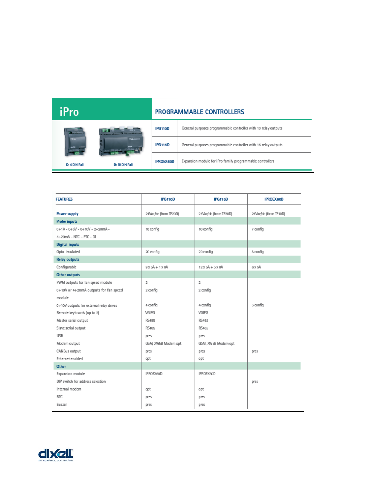
3.2 Technical data
LINUX Operative System
200MHz CPU
32bit processor
32MB RAM memory
128MB flash memory capacity (80MB free)
10 configurable Analog Inputs (configurable as Digital Inputs)
6 Analog Outputs (configurable as Digital Outputs)
20 Digital Inputs (free contacts)
15 Digital Outputs (Relay 5A)
Ethernet 10/100
Modem (Internal and External)
2 Master bus (RS485 and Can-bus)
1 Slave bus (RS485 MODBUS RTU)
1 USB
1 VISOGRAPH connection
Power Supply: 24 Vac-dc
Operating temperature: -10 ÷ 60 °C
Storage temperature: -20 ÷ 70 °C
Relative humidity: < 90% (no condensing)
Power consumption: 10W
Protection: IP20 (IP40 for VISOGRAPH)

________________________________________________________________________________________________________
1592025400 – Vers. 1.0 - 9 -
3.3 Alarm Management
The alarm management system is the fundamental element that increases the plant
efficiency, ensuring an immediate identification of plant problems and activates automatic
strategies to prevent possible damages. The following possible options are available with
iPro GENIUS.
• Alarm sending management by e-mail or sms
• Direct internet connection
• Point-to-point connection via modem, GSM and PDA modem
• Remote command sending via sms
• Possibility of updating the (iPro) on-board software via e-mail
3.4 Plant Status Display
The plant maintenance staff can easily have a report of application status in order to decide
how and when to intervene. The report contains all of the most important values, the plant
status and operating set point.
3.5 ISaGRAF
In order to create programs that will be uploaded into the iPro series Dixell has selected
ISaGRAF®; a software environment that enables you to create local or distributed control
systems. ISaGRAF® offers a combination of a highly portable, robust management engine
(Virtual Machine) and an intuitive application development environment (Workbench). The
output of the development environment is selectable as either portable “C” source code or
TIC (target independent code). The ISaGRAF® Virtual Machine is a powerful, optimized
and very fast control engine that executes the TIC. Virtual Machine and all options are
offered ready to use on NT, Linux, CE 3.0 and QNX. Additionally, this control engine has
been designed such that the source code of the Virtual Machine is available in a toolkit

________________________________________________________________________________________________________
1592025400 – Vers. 1.0 - 10 -
format, providing portability to any OS on any hardware platform. The Enhanced options for
ISaGRAF® transform this outstanding controller into a top of the line PLC, DCS or RTU.
3.6 Why ISaGRAF ?
• This development environment is international, complete, standard
• Is ideal for small applications but it can manage several I/O points
• It is the most used (more than 40.000 developers in the world and more than
500.000 applications in the last 10 years)
• It includes 5 different programming languages coded according to IEC61131
• It integrates the best system for simulation and remote debugging
• It is supported all over the world (essential for training and assistance)
The ISaGRAF® Application development Workbench supports all the standard IEC 61131
control program languages plus Flow Chart.
• SFC: Sequencial Function Chart
• ST: Structured Text
• FBD: Function Block Diagram
• IL: Instruction List
• FC: Flow Chart
• LD: Ladder Diagram
3.7 Development tools
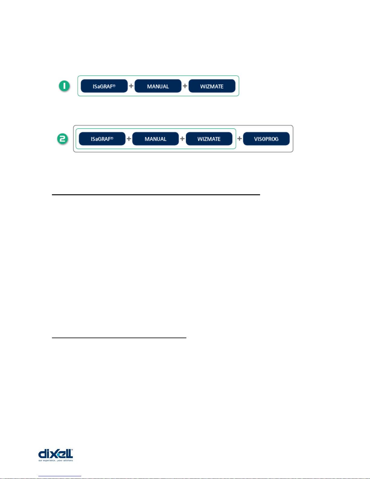
IPRO-TOOL is a complete tool, provided by Dixell, that allows the final user to work
independently to create programs for iPRO controllers, taking advantage of all the
programmable series potential. The package includes manuals and the WIZMATE software,
a useful instrument that allows a simple iPRO controllers programming mode. Another utility
provided by Dixell is the VISOPROG software for the graphic interfaces creation of
VISOGRAPH displays.
________________________________________________________________________________________________________
1592025400 – Vers. 1.0 - 11 -
The user can choose between two options:
3.8 Upgrade programs from previous version of ISaGRAF (3.x)
For iPRO is possible to manage programs that have been developed with ISaGRAF 3.x
version; it is not possible the opposite.
If the program contains ISaGRAF standard function block, they can be converted
automatically.
If the program contains ISaGRAF custom functional block (for example blocks made from
other company), it will be necessary to codify and rewrite them for the new version.
3.9 Minimum system requirement for PC
When connecting through the LAN, the PC client computer must have installed these
components:
• Windows 98®, Windows 2000, WindowsXP.
• Pentium II 300MHz with 64Mb ram or higher
• Java Virtual Machine
• Explorer 5.5 or higher, Firefox

________________________________________________________________________________________________________
1592025400 – Vers. 1.0 - 12 -
If necessary, inside the CD-ROM you will find the Java Virtual Machine program distributed
by Sun® Microsystems.
Dixell S.p.a. is not responsible for any kind of damage occurring after the loading of the
Java Virtual Machine program into the user’s PC.
3.10 Inside the packaging
________________________________________________________________________________________________________
1592025400 – Vers. 1.0 - 13 -
4. BASIC Input/Output CONFIGURATION
Configurable means that every inputs or output can be configured different each other.
________________________________________________________________________________________________________
1592025400 – Vers. 1.0 - 14 -
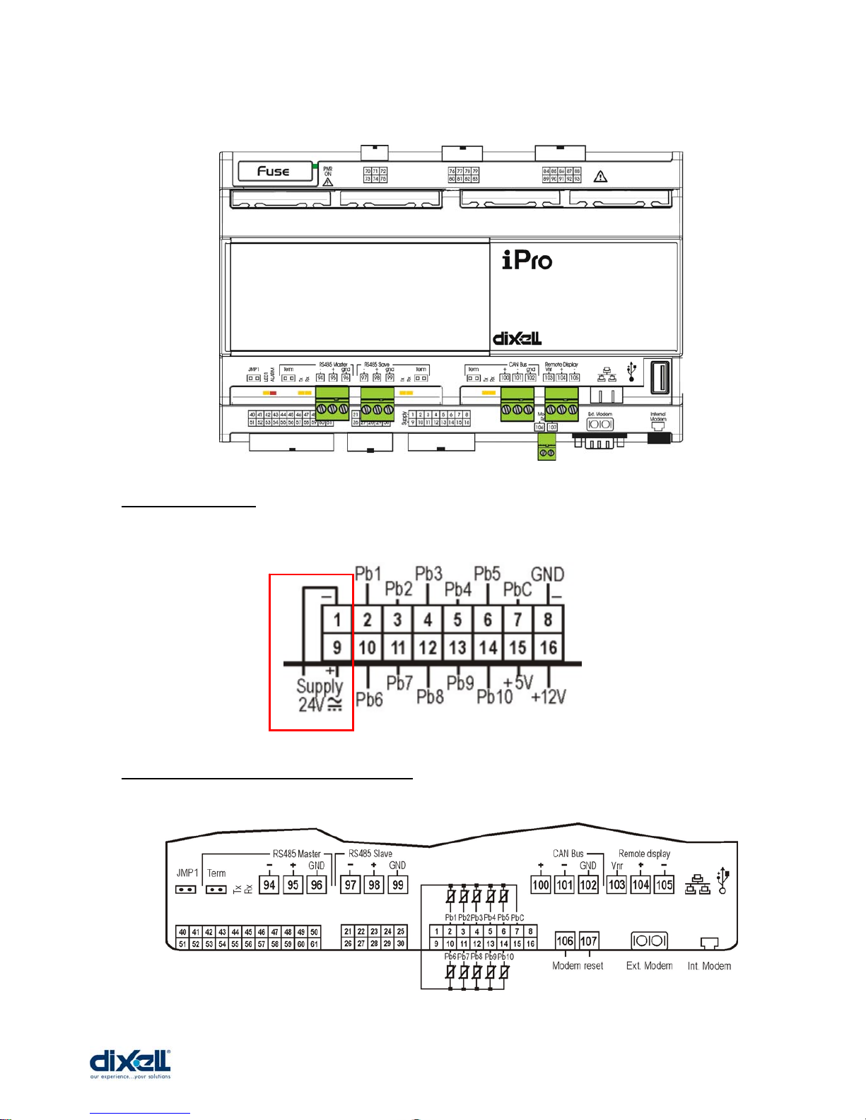
4.1 Power Supply
4.2 Analog Inputs (Probes PTC-NTC)

________________________________________________________________________________________________________
1592025400 – Vers. 1.0 - 15 -
4.3 Analog Inputs (Pressure transducers 4÷20mA, probes 0÷20mA)
4.4 Analog Inputs (Pressure transducers 0÷1V, Ratiometric 0÷5V - 0÷10V)
4.5 Analog Inputs (Probes 0÷1V - 0÷10V)
________________________________________________________________________________________________________
1592025400 – Vers. 1.0 - 16 -
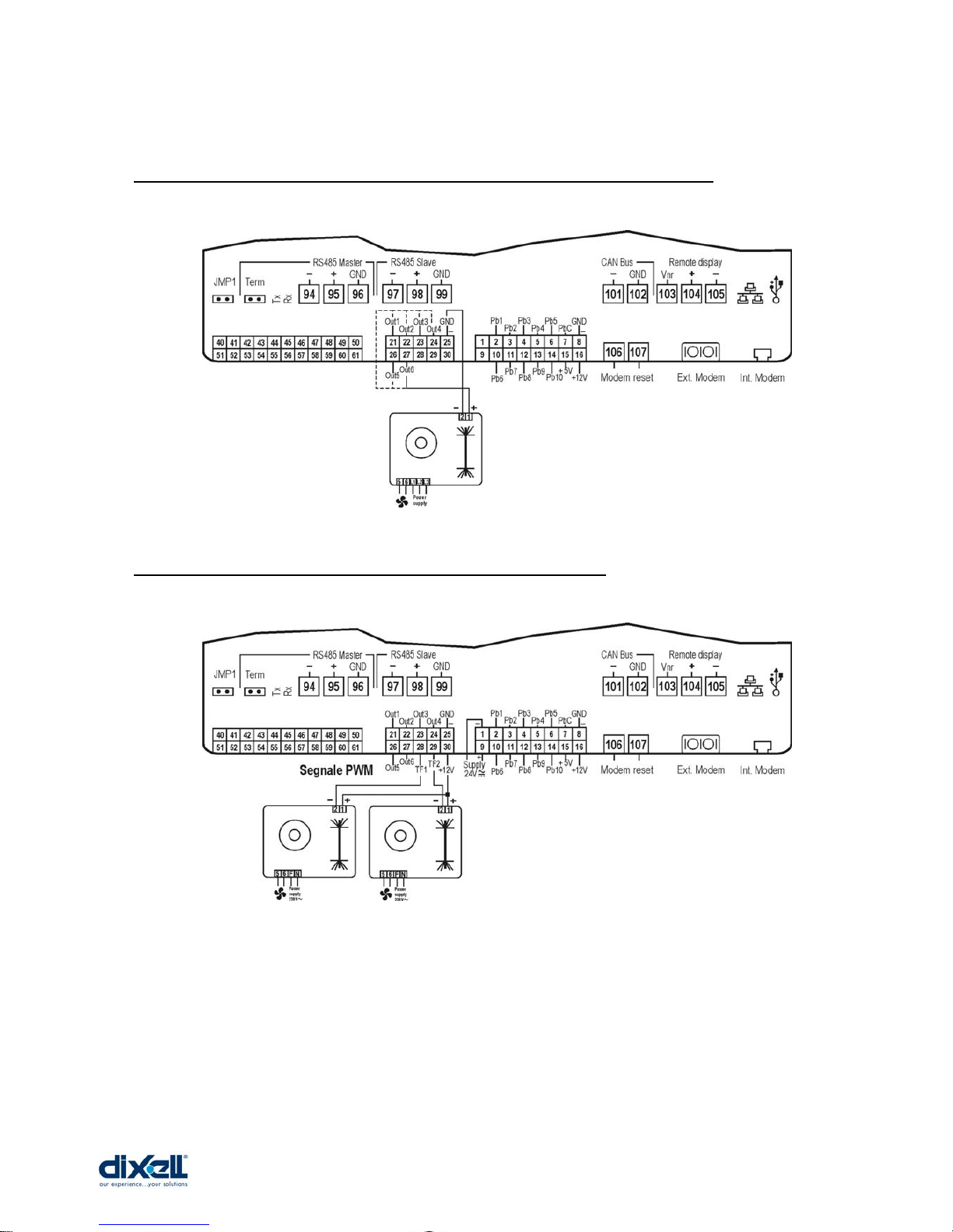
4.6 Analog Outputs (0÷10V - 4÷20mA signal for condenser controls)
4.7 Analog Outputs (PWM signal for fan speed module)
________________________________________________________________________________________________________
1592025400 – Vers. 1.0 - 17 -
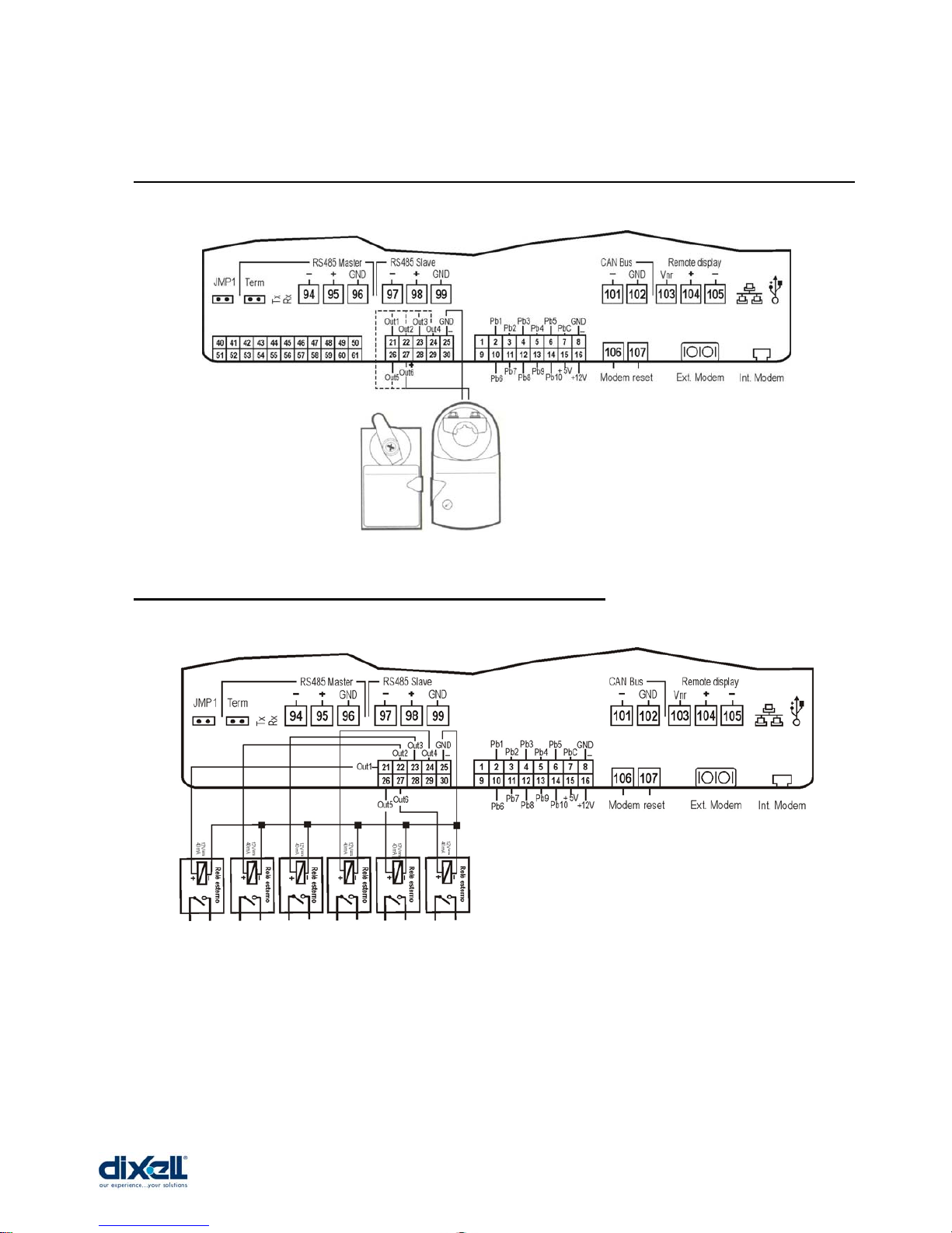
4.8 Analog Outputs (proportional signal 0÷10V, 4÷20mA for actuators/ servo-motors)
4.9 Analog Outputs (configured to control remote relay)
________________________________________________________________________________________________________
1592025400 – Vers. 1.0 - 18 -
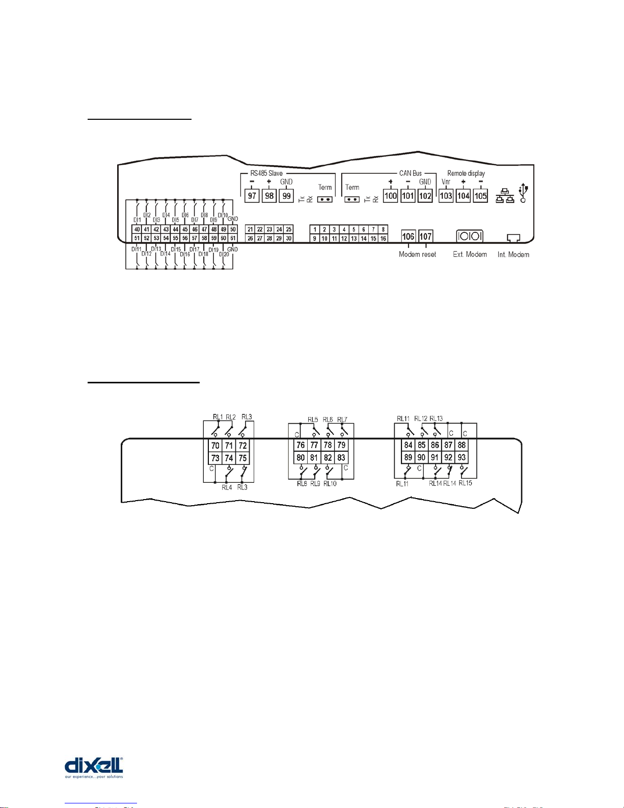
4.10 Digital Inputs
4.11 Digital Outputs
________________________________________________________________________________________________________
1592025400 – Vers. 1.0 - 19 -
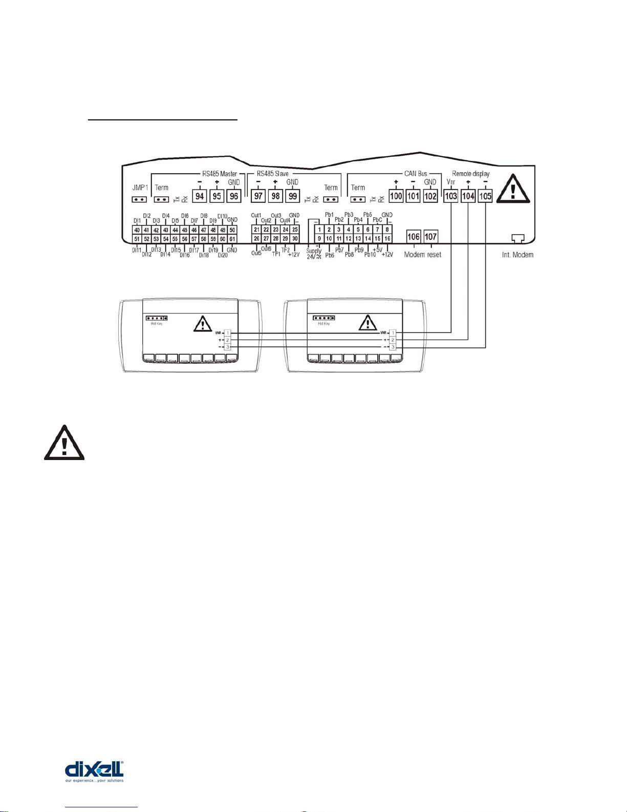
4.12 Visograph connection
IT IS VERY IMPORTANT TO RESPECT THE POLARITY OF CONNECTIONS TO AVOID
THE DAMAGING OF THE VISOGRAPH.
________________________________________________________________________________________________________
1592025400 – Vers. 1.0 - 20 -
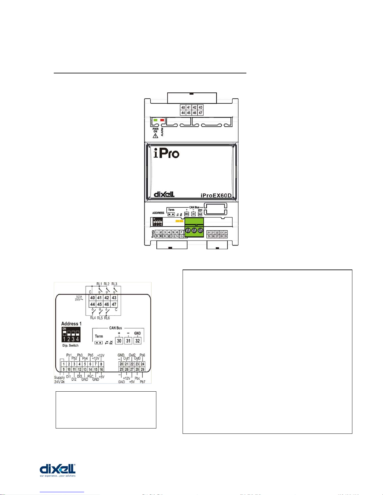
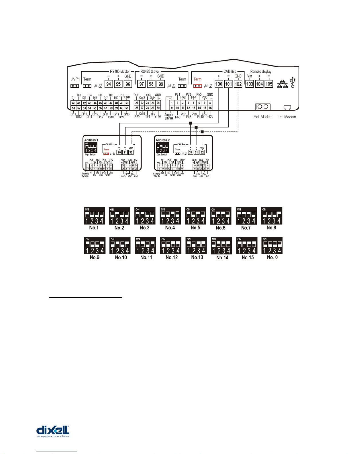
4.13 Expansion Module (specifications and connections)
Power supply: 24V Vac/dc
Analog Inputs: 7 configurable
0÷1V, 0÷5V, 0÷10V,
0÷20mA, 4÷20mA, NTC, PTC, DI
Analog Outputs: 3 configurable
0÷10V ( or DO for relay)
Digital Inputs: 3 (free contacts)
Digital Output: 6 relay 5A 250V
Connection: 1 CANBus
Address: Dip switch 4 positions
Can bitrate = 100Kbit/s
(set-up this value
through the browser
________________________________________________________________________________________________________
1592025400 – Vers. 1.0 - 21 -
4.14 Other connections
For all the other connections, please refer to the section No. 14.
________________________________________________________________________________________________________
1592025400 – Vers. 1.0 - 22 -
5. HOW TO START
5.1 Ethernet 10/100 connection
With this connection is possible:
• To connect the iPRO with the personal computer; through ISaGRAF workbench you
download and debug the application.
• To connect more iPRO; different applications on different iPRO to exchanges
variables.
• To send mail and sms; you can program your iPRO so that it can sends mail/sms on
time or on demand.
• To visit your own website; you can program iPRO with your own web site. With a
standard browser, a user can read/write variables.
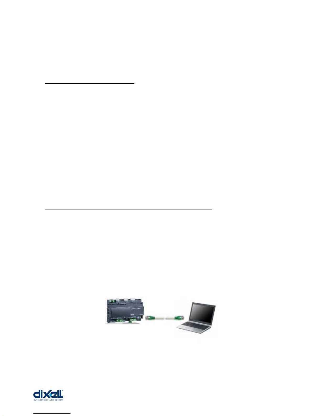
5.2 Direct connection (between iPRO and PC with a cable)
With this kind of connection is possible to connect directly your personal computer with the
programmable controller iPRO. In this case, you need a standard “Crossover Cable” (cod.
Dixell CAB/WEB/PC). The PC can communicate with the iPRO only if the settings in the
devices are aligned; this means that the PC and the iPRO have to work in the same
network.
The procedure is the following:
Cable
(Crossover)
________________________________________________________________________________________________________
1592025400 – Vers. 1.0 - 23 -
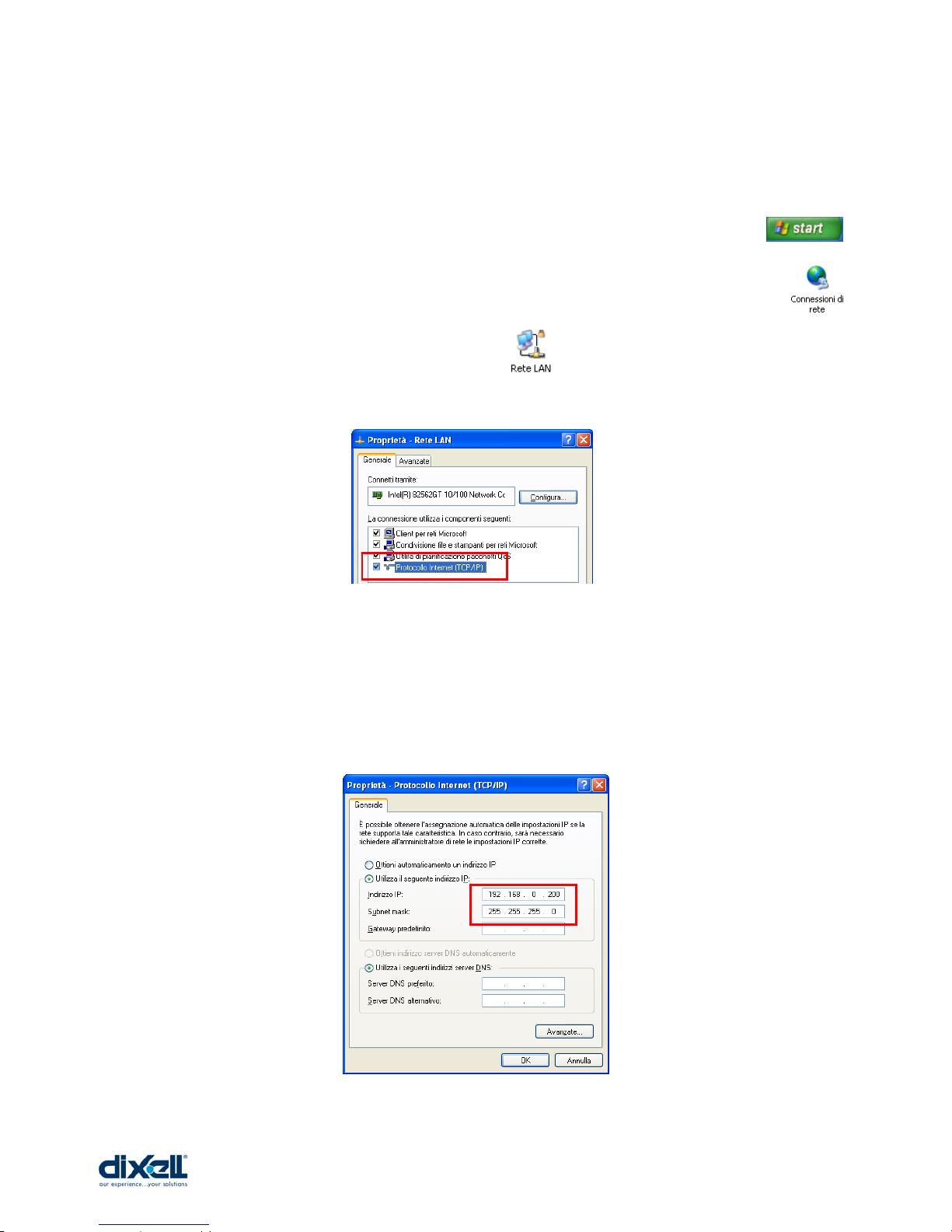
• Disconnect your computer from the data network of your company and connect the
PC with the iPRO through the Crossover cable.
• The personal computer has to be set in the same network of the iPRO.
o In the windows environment click with the mouse on “start” button .
o Choose “Control Panel” and selec t “Network and dial-up connections” .
o Choose “Local area connection” .
o Choose “Properties” and double click on “Internet Protocol (TCP/IP)”.
o In this window set the following parameters (as showed in the picture):
IP address: 192.168.0.200
Subnet Mask: 255.255.255.0
o Click “OK” to confirm.
________________________________________________________________________________________________________
1592025400 – Vers. 1.0 - 24 -
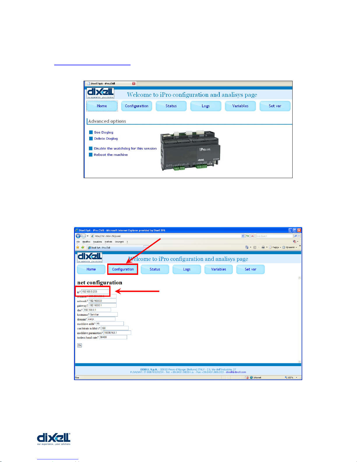
Launch the browser in your computer and write the following web site address:
http://192.168.0.250/panel (if your IP is different, write the correct one):
If necessary is possible to change the IP address; click the Configuration button and in the
IP box write the new address (for example if your IP address is: 192.168.0.233).
Click “OK” to confirm the operation.
________________________________________________________________________________________________________
1592025400 – Vers. 1.0 - 25 -
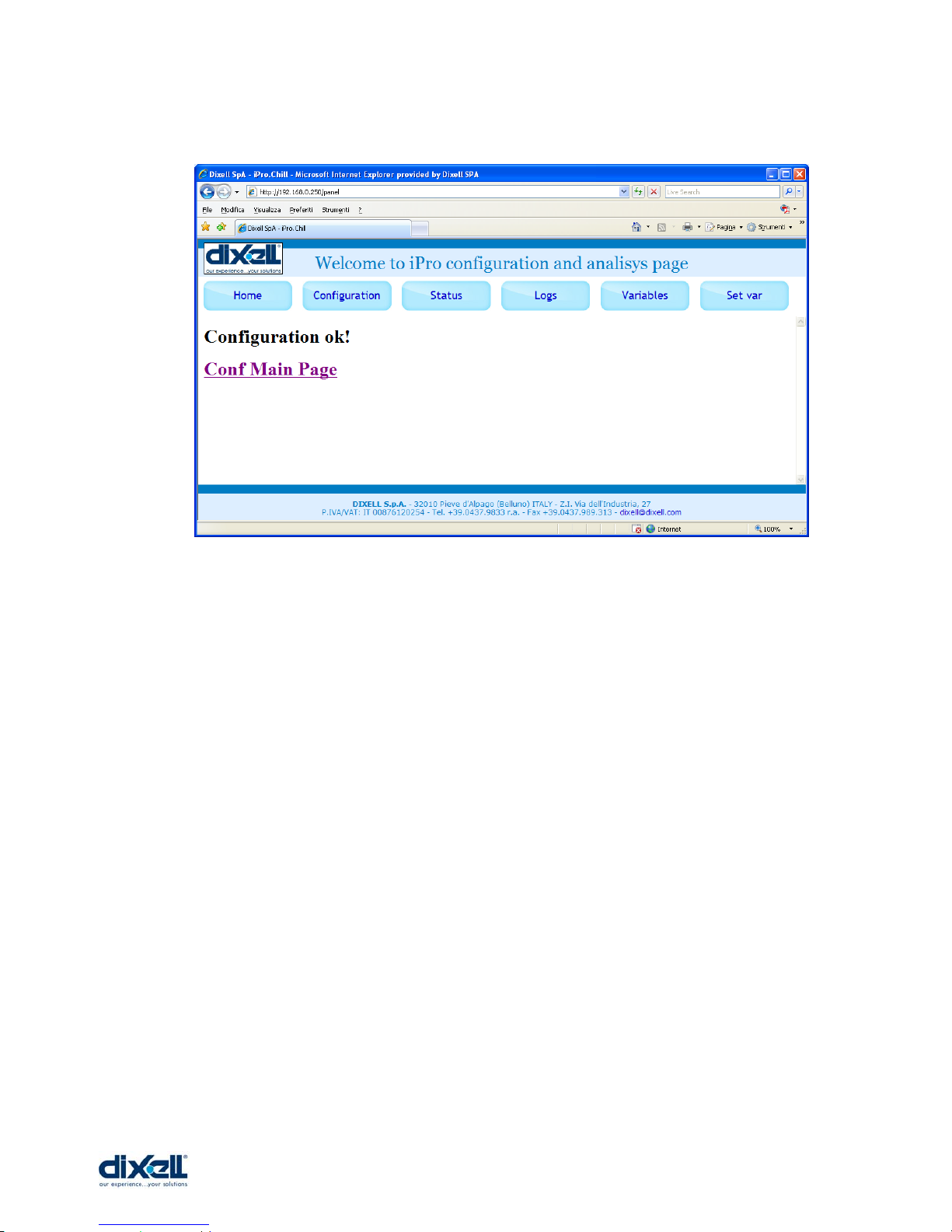
If everything is ok, the message will be:
Now it is necessary to restart the iPRO.
To test the connection follows the procedure in the chapter 5.3.
________________________________________________________________________________________________________
1592025400 – Vers. 1.0 - 26 -
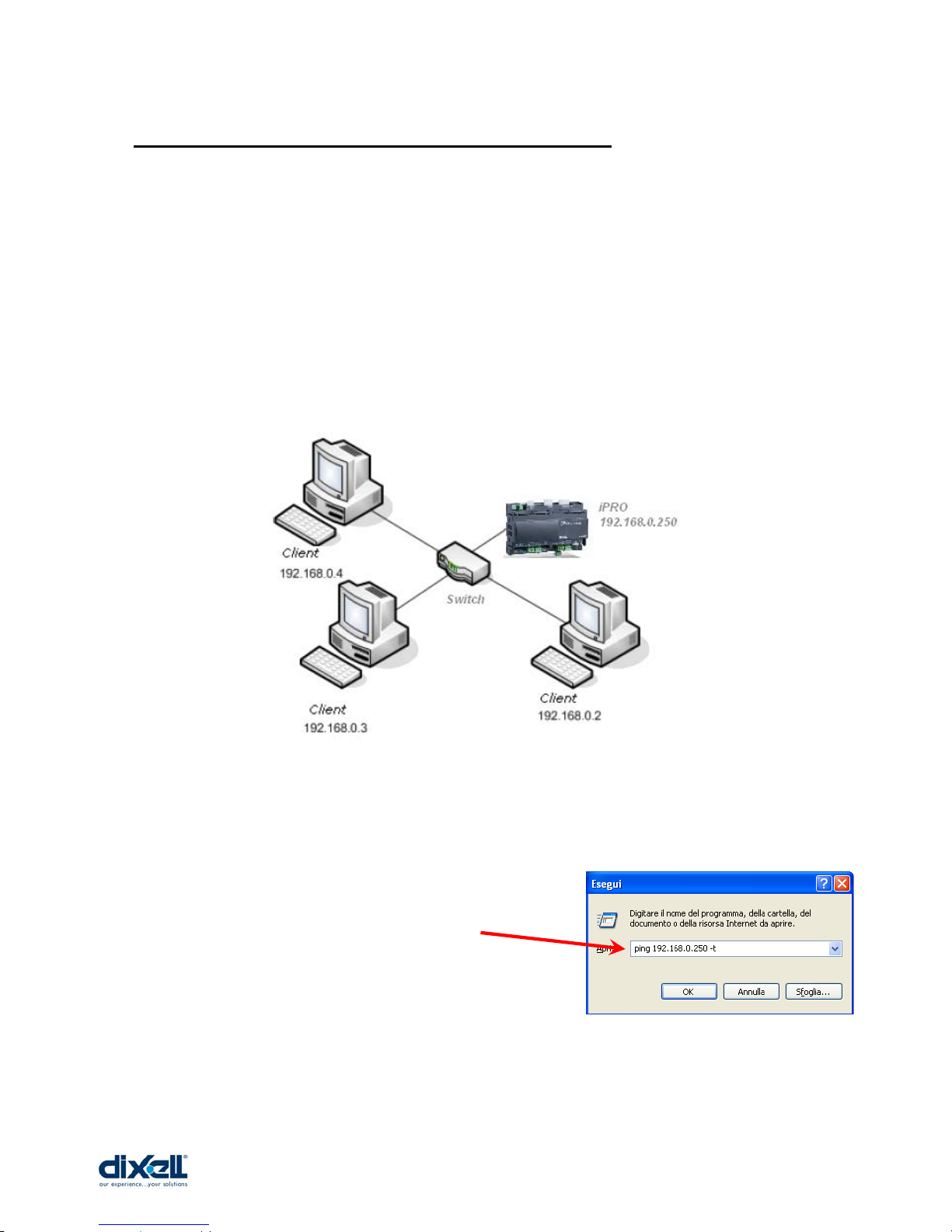
5.3 Intranet / Ethernet connection (Local Area Network)
The Intranet or Ethernet connection should be initially managed by the net administrator
that will assign one free IP address to reach the iPRO. This number is an example of what
you should expect with the default IP of the iPRO: 192.168.0.250.
After receiving the address from your network Administrator the iPRO must be set with this
number (through the procedure described in the chapter 5.2).
Use a standard RJ45 network cable to connect the unit to your existing LAN.
The Intranet method allows the connection to interact with iPRO from all the PC Clients.
To check if the connection has been established try in this way:
• From your computer launch: start -Æ run
• In the box write the following string:
• Then click OK.

________________________________________________________________________________________________________
1592025400 – Vers. 1.0 - 27 -
If the connection is OK, in this window you will see the following information:
5.4 Port forwarding
Port forwarding allows remote computers (e.g. public machines on the Internet) to connect
to a specific computer within a private LAN.
The ports that have to be opened are:
• 22 for SSH protocol
• 80 for browser (internet explorer, firefox, …)
• 1131 for ISaGRAF WorkBench
• 6666 used for remote update
5.5 Modem connection
________________________________________________________________________________________________________
1592025400 – Vers. 1.0 - 28 -
6. ISAGRAF INSTALLATION AND SET-UP
6.1 Requirements
To develop the software with ISaGRAF are necessary:
• Software (it is possible to install the program from the CD or download it from the
ISaGRAF Website).
• To have the ISaGRAF USB KEY
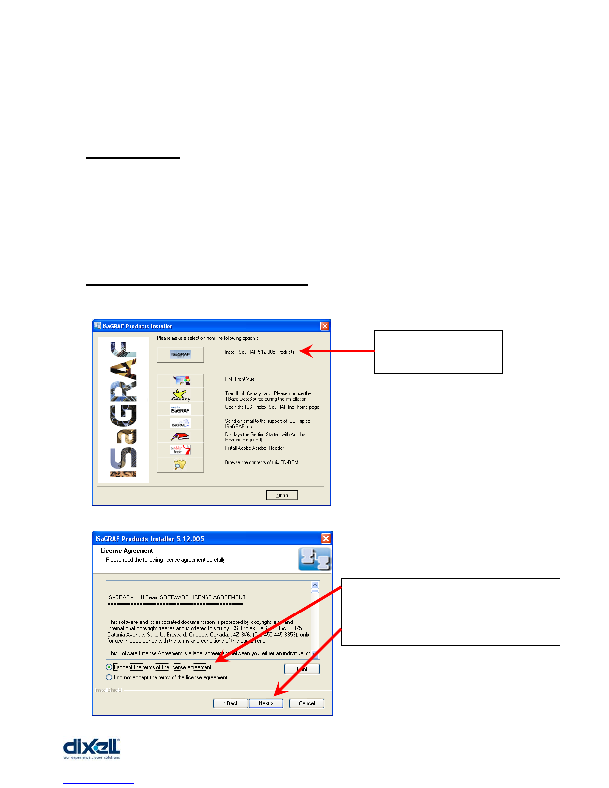
6.2 How to install the ISaGRAF software
Insert the CD in your computer; the CD will start automatically.
You have to choose
the first option.
You have to select: “ I accept the terms”
…and then: “Next”
________________________________________________________________________________________________________
1592025400 – Vers. 1.0 - 29 -
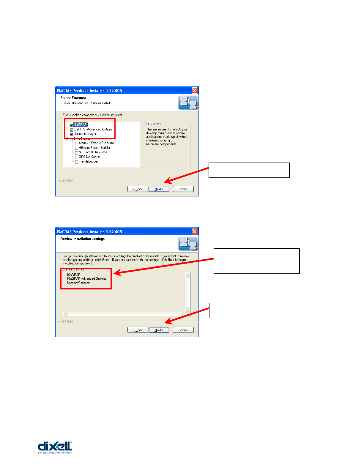
Please install ONLY the programs selected as showed here below:
…and then: “Next”
…and then: “Next”
These are the programs
that you are installing…
________________________________________________________________________________________________________
1592025400 – Vers. 1.0 - 30 -
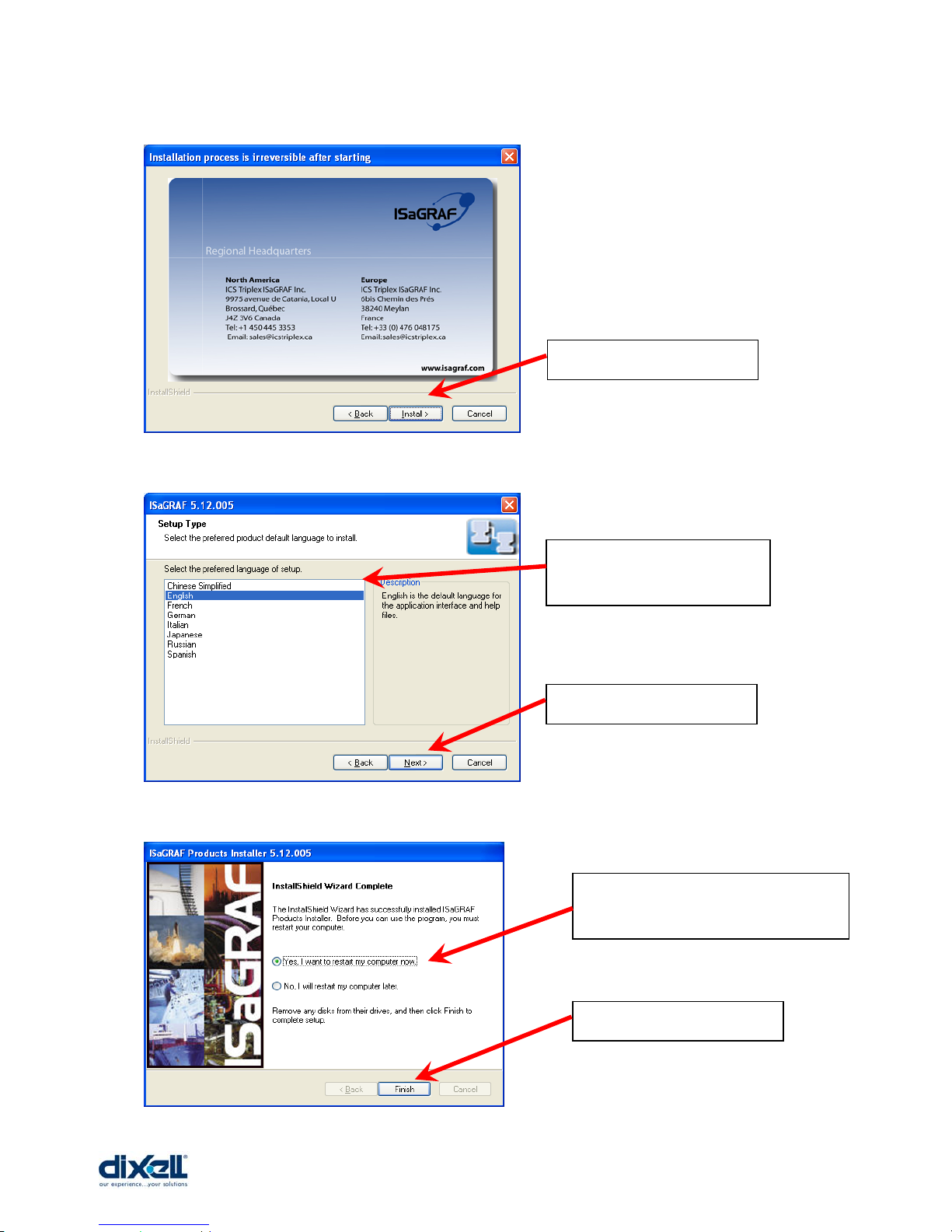
…select: “Install”
Choose the languages…
…select: “Next”
At the end of the installation,
please restart the computer
…select: “Finish”
 Loading...