

dixell IPX125D, IPX225D, IPX115D, IPX215D, IPG108D Installing And Operating Insructions
...Page 1
iPro SERIES
(V.3.2)
Page 2

Page 3

1592025700 IPROFAMILY stp GB 2012.08.08.doc iPro Series 3/72
INDEX
1. IMPORTANT RECOMMENDATIONS 5
1.1 PRODUCT DISPOSAL (WEEE) 6
2. INTRODUCTION 7
3. GENERAL SPECIFICATIONS 8
3.1 PROCESSING ENVIRONMENT 8
3.1.1 Fields of application ................................................................................................................................................................ 8
3.1.2 Hardware architecture ............................................................................................................................................................ 8
4. VERSIONS OF THE PROGRAMMABLE CONTROLLERS 10
4.1 IPRO.GENIUS AND IPRO.CHILL (IPG100D – IPC100D RANGES) 11
4.1.1 Description of the connections ............................................................................................................................................. 12
4.1.2 Description of the inputs and outputs ................................................................................................................................... 13
4.1.3 Technical specifications ....................................................................................................................................................... 16
4.1.3.1 Analogue inputs ........................................................................................................................................................... 16
4.1.3.2 Digital inputs ................................................................................................................................................................ 16
4.1.3.3 Analogue outputs ........................................................................................................................................................ 16
4.1.3.4 Standard Digital outputs .............................................................................................................................................. 17
4.1.3.5 SSR Digital outputs version ......................................................................................................................................... 17
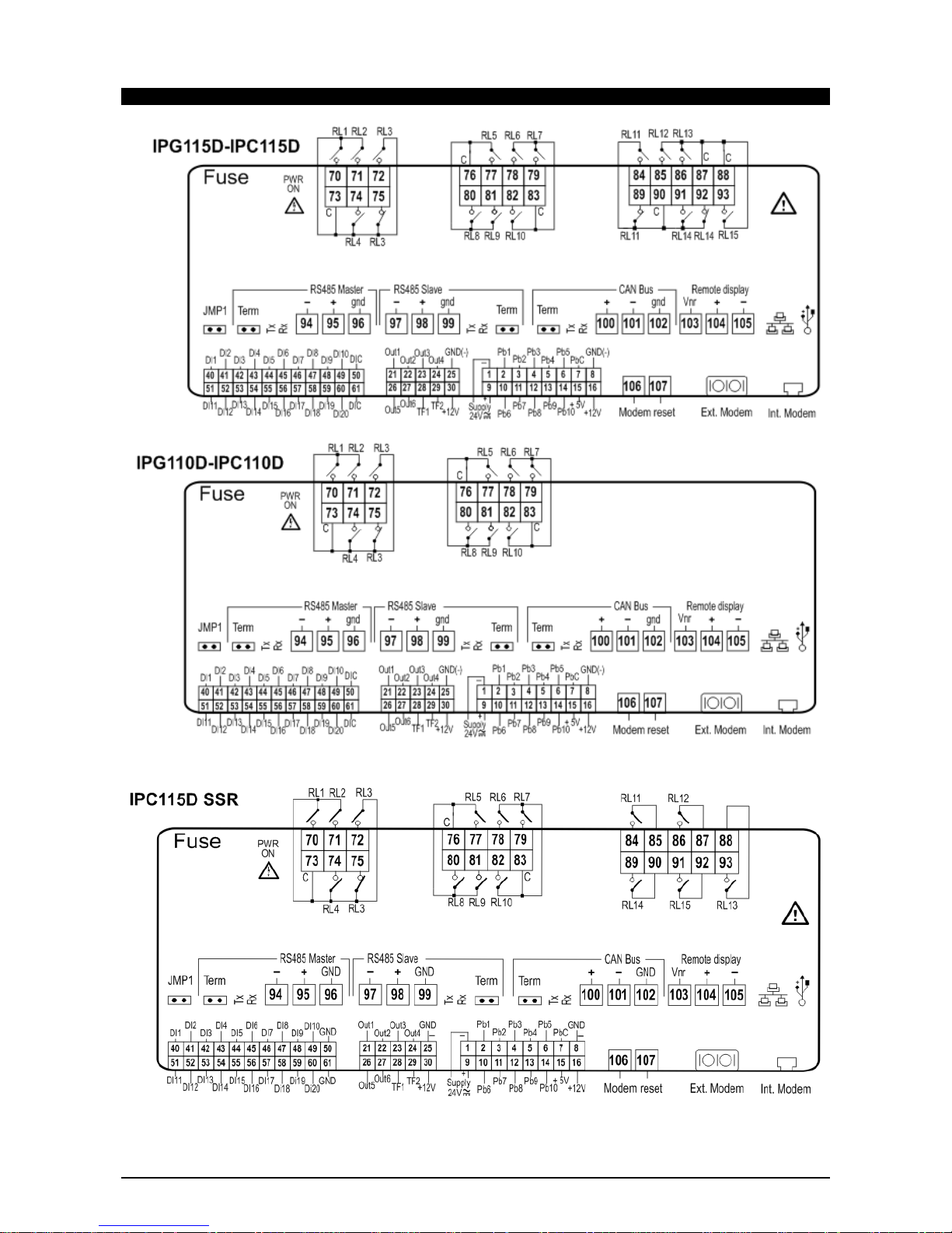
4.1.3.6 Wiring diagrams .......................................................................................................................................................... 18
4.1.3.7 Mechanical specifications ............................................................................................................................................ 19
4.1.3.8 Electrical specifications ............................................................................................................................................... 19
4.1.3.9 Plastic container .......................................................................................................................................................... 19
4.1.3.10 Product certifications ................................................................................................................................................... 19
4.2 IPRO.GENIUS (IPG200D RANGE) 20
4.2.1 Description of the connections ............................................................................................................................................. 21
4.2.2 Description of the inputs and outputs ................................................................................................................................... 22
4.2.3 Technical specifications ....................................................................................................................................................... 24
4.2.3.1 Analogue inputs ........................................................................................................................................................... 24
4.2.3.2 Digital inputs ................................................................................................................................................................ 24
4.2.3.3 Analogue outputs ........................................................................................................................................................ 24
4.2.3.4 Digital outputs .............................................................................................................................................................. 24
4.2.3.5 Wiring diagrams .......................................................................................................................................................... 25
4.2.3.6 Mechanical specifications ............................................................................................................................................ 25
4.2.3.7 Electrical specifications ............................................................................................................................................... 25
4.2.3.8 Plastic container .......................................................................................................................................................... 26
4.2.3.9 Product certifications ................................................................................................................................................... 26
4.3 IPRO 4 DIN (IPG100D – IPG200D – IPC100E RANGES) 27
4.3.1 Description of the connections ............................................................................................................................................. 27
4.3.2 Description of the inputs and outputs ................................................................................................................................... 28
4.3.3 Technical specifications ....................................................................................................................................................... 29
4.3.3.1 Analogue inputs ........................................................................................................................................................... 29
4.3.3.2 Digital inputs ................................................................................................................................................................ 29
4.3.3.3 Analogue outputs ........................................................................................................................................................ 30
4.3.3.4 Digital outputs .............................................................................................................................................................. 30
4.3.3.5 Wiring diagrams .......................................................................................................................................................... 30
4.3.3.6 Mechanical specifications ............................................................................................................................................ 31
4.3.3.7 Electrical specifications ............................................................................................................................................... 31
4.3.3.8 Plastic container .......................................................................................................................................................... 31
4.3.3.9 USB-ETHERNET Adapter ........................................................................................................................................... 31
4.4 IPRO.LINK (IPL500D) 32
4.4.1 Description of the connections ............................................................................................................................................. 32
4.4.2 Description of the inputs and outputs ................................................................................................................................... 33
4.4.3 Technical specifications ....................................................................................................................................................... 33
4.4.3.1 Wiring diagrams .......................................................................................................................................................... 33
4.4.3.2 Mechanical specifications ............................................................................................................................................ 34
4.4.3.3 Electrical specifications ............................................................................................................................................... 34
4.4.3.4 Plastic container .......................................................................................................................................................... 34
4.5 IPX106D 35
4.5.1 Description of the connections ............................................................................................................................................. 35
4.5.2 Description of the inputs and outputs ................................................................................................................................... 36
4.5.3 Technical specifications ....................................................................................................................................................... 37
4.5.3.1 Analogue inputs ........................................................................................................................................................... 37
4.5.3.2 Digital inputs ................................................................................................................................................................ 37
4.5.3.3 Analogue outputs ........................................................................................................................................................ 37
4.5.3.4 Digital outputs .............................................................................................................................................................. 37
4.5.3.5 Wiring diagrams .......................................................................................................................................................... 38
4.5.3.6 Mechanical specifications ............................................................................................................................................ 38
4.5.3.7 Electrical specifications ............................................................................................................................................... 38
Page 4

1592025700 IPROFAMILY stp GB 2012.08.08.doc iPro Series 4/72
4.5.3.8 Plastic container .......................................................................................................................................................... 39
4.5.3.9 Setting the address of the device ................................................................................................................................ 39
4.6 IPX125D – IPX115D 40
4.6.1 Description of the connections ............................................................................................................................................. 40
4.6.2 Description of the inputs and outputs ................................................................................................................................... 41
4.6.3 Technical specifications ....................................................................................................................................................... 43
4.6.3.1 Analogue inputs ........................................................................................................................................................... 43
4.6.3.2 Digital inputs ................................................................................................................................................................ 43
4.6.3.3 Analogue outputs ........................................................................................................................................................ 43
4.6.3.4 Digital outputs .............................................................................................................................................................. 44
4.6.3.5 Wiring diagrams .......................................................................................................................................................... 44
4.6.3.6 Mechanical specifications ............................................................................................................................................ 45
4.6.3.7 Electrical specifications ............................................................................................................................................... 45
4.6.3.8 Plastic container .......................................................................................................................................................... 45
4.6.3.9 Setting the address of the device ................................................................................................................................ 45
4.7 IPX225D – IPX215D 46
4.7.1 Description of the connections ............................................................................................................................................. 46
4.7.2 Description of the inputs and outputs ................................................................................................................................... 47
4.7.3 Technical specifications ....................................................................................................................................................... 49
4.7.3.1 Analogue inputs ........................................................................................................................................................... 49
4.7.3.2 Digital inputs ................................................................................................................................................................ 49
4.7.3.3 Analogue outputs ........................................................................................................................................................ 49
4.7.3.4 Digital outputs .............................................................................................................................................................. 50
4.7.3.5 Wiring diagrams .......................................................................................................................................................... 50
4.7.3.6 Mechanical specifications ............................................................................................................................................ 51
4.7.3.7 Electrical specifications ............................................................................................................................................... 51
4.7.3.8 Plastic container .......................................................................................................................................................... 51
4.7.3.9 Setting the address of the device ................................................................................................................................ 51
5. INTERFACE 52
5.1 VISOGRAPH 52
5.1.1 Specifications ....................................................................................................................................................................... 52
5.1.2 Connections ......................................................................................................................................................................... 53
5.1.3 Options menu ....................................................................................................................................................................... 53
5.1.4 Dimensions ........................................................................................................................................................................... 54
6. MEANING OF THE LEDS AND JUMPERS IN THE VARIOUS DEVICES 55
6.1 PROGRAMMABLE CONTROLLERS 55
6.2 EXPANSION MODULES 55
7. INSTALLATION 56
7.1 GENERAL RULES 56
7.2 POWER SUPPLY 56
7.3 CONNECTION OF THE ANALOGUE INPUTS 57
7.3.1 Temperature probes (NTC and PTC) ................................................................................................................................... 57
7.3.2 Pressure transducers and current probes (0 - 20mA, 4 - 20mA) ......................................................................................... 57
7.3.3 Pressure transducers and ratiometric pressure transducers (0 - 5V) ................................................................................... 58
7.3.4 Live probes (0 - 1V, 0 - 5V, 0 - 10V) ..................................................................................................................................... 58
7.3.5 Probes and transducers with 24Vac/dc power supply .......................................................................................................... 59
7.4 CONNECTION OF THE DIGITAL INPUTS 60
7.4.1 Potential-free digital inputs ................................................................................................................................................... 60
7.4.2 Live digital inputs (24Vac/dc) ............................................................................................................................................... 61
7.5 CONNECTION OF THE ANALOGUE OUTPUTS 61
7.5.1 0 - 10V, 4 - 20mA Analogue output for condensation control .............................................................................................. 62
7.5.2 PWM analogue output for condensation control .................................................................................................................. 63
7.5.3 0 - 10V, 4 - 20mA Proportional analogue output for servomotors/actuators ........................................................................ 63
7.5.4 Devices with 24Vac/dc power supply ................................................................................................................................... 64
7.5.5 Analogue output for relays (coil power supply 12Vdc) ......................................................................................................... 65
7.6 CONNECTION OF THE DIGITAL OUTPUTS 65
7.7 CANBUS CONNECTION 66
7.8 RS485 SLAVE CONNECTIONS 67
7.9 RS485 MASTER CONNECTION 68
Page 5

1592025700 IPROFAMILY stp GB 2012.08.08.doc iPro Series 5/72
1. IMPORTANT RECOMMENDATIONS
¾ The symbol alerts the user of non-insulated “dangerous voltage” within the product area that
is sufficiently high to constitute a risk of electric shock to persons.
¾ The
symbol alerts the user of important operating and maintenance (assistance) instructions
found in the documentation attached to the device.
¾ Dixell Srl cannot accept any liability for damages caused by modems that are not supported. Dixell
Srl reserves the right to modify this manual without prior notice. The documentation can be
downloaded from www.dixell.com even prior to purchase.
¾ This manual forms part of the product and must always be kept near the device for easy and quick
reference. The device cannot be used as a safety device. Verify the limits of application before using
the device.
¾ Verify that the power supply voltage is correct before connecting the device. Do not expose it to
water or humidity: use the controller only within the operating limits, avoiding sudden changes in
temperature and high atmospheric humidity in order to prevent condensation from forming.
Recommendation: disconnect all the electric connections before performing any maintenance. Insert
the probe where it cannot be reached by the End User. The device must not be opened. Consider
the maximum current that can be applied to each relay. Make sure that the wires for the probes, the
loads and the electrical power supply are separated and sufficiently distant from each other, without
crossing or intertwining with each other. In the case of applications in industrial environments, it may
be useful to use the main filters (our mod. FT1) in parallel to the inductive loads.
¾ The customer shall bear full responsibility and risk for product configuration in order to achieve the
results pertaining to installation and/or final equipment/system. Upon the customer's request and
following a specific agreement, Dixell s.r.l. may be present during the start-up of the final
machine/application, as a consultant, however, under no circumstances can the company be held
responsible for the correct operation of the final equipment/system.
¾ Since Dixell products form part of a very high level of technology, a
qualification/configuration/programming/commissioning stage is required to use them as best as
possible. Otherwise, these products may malfunction and Dixell cannot be held responsible. The
product must not be used in any way that differs from that stipulated in the documentation.
• The device must always be inserted inside an electrical panel that can only be accessed by
authorised personnel. For safety purposes, the keyboard must be the only part that can be reached.
• The device must never be hand-held while being used.
¾ It is good practice to bear the following in mind for all Dixell products:
o Prevent the electronic circuits from getting wet as contact made with water, humidity or any
other type of liquid can damage them. Comply with the temperature and humidity limits
specified in the manual in order to store the product correctly.
o The device must not be installed in particularly hot environments as high temperatures can
damage it (electronic circuits and/or plastic components forming part of the casing). Comply
with the temperature and humidity limits specified in the manual in order to store the product
correctly.
Page 6

1592025700 IPROFAMILY stp GB 2012.08.08.doc iPro Series 6/72
o Under no circumstances is the device to be opened - the user does not require the internal
components. Please contact qualified service personnel for any assistance.
o Prevent the device from being dropped, knocked or shaken as either can cause irreparable
damage.
o Do not clean the device with corrosive chemical products, solvents or aggressive detergents.
o The device must not be used in applications that differ from that specified in the following
material.
¾ Separate the power of the device from the rest of the electrical devices connec ted inside the
electrical panel. The secondary of the transformer must never be connected to the earth.
¾ Dixell Srl reserves the right to change the composition of its products, even without notice,
ensuring the same and unchanged functionality."
1.1 PRODUCT DISPOSAL (WEEE)
With reference to Directive 2002/96/EC of the European Parliament and of the Council of 27 January
2003 and to the relative national legislation, please note that:
¾ There lies the obligation not to dispose of electrical and electronic waste as municipal waste but to
separate the waste.
¾ Public or private collection points must be used to dispose of the goods in accordance with local
laws. Furthermore, at the end of the product's life, it is also possible to return this to the retailer when
a new purchase is made.
¾ This equipment may contain hazardous substances. Improper use or incorrect disposal can have
adverse effects on human health and the environment.
¾ The symbol shown on the product or the package indicates that the product has been placed on the
market after 13 August 2005 and must be disposed of as separated waste.
¾ Should the product be disposed of incorrectly, sanctions may be applied as stipulated in applicable
local regulations regarding waste disposal.
Page 7

1592025700 IPROFAMILY stp GB 2012.08.08.doc iPro Series 7/72
2. INTRODUCTION
iPRO is the range of programmable controllers manufactured by Dixell.
The range consists of programmable controllers, I/O expansions, drivers for electronic valves and graphical
interfaces adapted to cover any type of application in the air-conditioning sector, cooling sector and any
relative area. As the system is one of the most technologically advanced, it is flexible and can be customised
for it to be adapted to the user’s particular requirements.
Page 8

1592025700 IPROFAMILY stp GB 2012.08.08.doc iPro Series 8/72
3. GENERAL SPECIFICATIONS
The Dixell programmable controllers are all powered at 24Vac/dc and use a high speed performance 32-bit
ARM9 (200 MHz) microprocessor. The models differ in size (10 DIN or 4 DIN) and number of inputs and
outputs (analogue and digital).
One of the features that distinguishes the iPRO controllers is the vast range of connection options with
external devices, Dixell as well as other brands. CANBus, RS485 Master and Slave, and an Ethernet and
USB port provide maximum flexibility of integration with the outside world. MODBUS RTU protocol, one of
the most popular in the world, is used for serial communication.
Up to 80 MB of flash memory are entirely available to the user, according to the model. All the inputs and
outputs are fully configurable.
3.1 PROCESSING ENVIRONMENT
All Dixell programmable controllers use the following software as a processing environment:
¾ ISaGRAF® to process the iPRO application.
¾ VISOPROG to process the LCD graphic interface application (VISOGRAPH)
ISaGRAF® software is used worldwide and allows those with no programming experience to build
applications ranging from the simplest to the more sophisticated. The vast range of the most popular
programming languages (Structured Text, Function Block Diagram, Ladder Diagram, Instruction List,
Sequential Function Chart, Flow Chart, FBD IEC 61499) provides all programmers with access to the
processing environment. Thanks also to the extensive libraries of blocks already developed by Dixell, the
processing and debug times are reduced.
The SIMULATION (verification of the application without using the controller) and DEBUG options
(verification of the actual application within the controller), allow the user to block and force the value of the
variables to speed up the testing times.
3.1.1 Fields of application
The possibility of all-round configuration allows the Dixell iPRO programmable controller to be used for any
type of application. The same applications can be downloaded in the various models available (obviously
adapting the number of inputs and outputs).
The hardware has already been used for the following applications:
¾ Chillers and heat pumps
¾ Air treatment units
¾ Air-conditioners
¾ Roof-tops
¾ Cooling systems
¾ Energy saving management in systems
¾ Climatic chamber control
¾ Cold rooms and seasoner cabinets
3.1.2 Hardware architecture
The iPRO programmable controller is structured as follows:
• 32-bit microprocessor used to run the application
• Removable connectors (Molex) or bayonet connectors (Phoenix)
• The programme and parameters are stored in a permanent flash memory. No data is lost in case of
power failure.
• Internal web server with the Dixell website as default with the option of downloading a customised
website for reading and writing variables with synoptic creation (via HTML).
• Ethernet port.
• USB port.
• Connection to the dedicated remote LCD display.
• CANBus.
Page 9

1592025700 IPROFAMILY stp GB 2012.08.08.doc iPro Series 9/72
• RS485 Master.
• RS485 Slave.
The remote LCD display has the following features:
• 240x96 pixel LCD graphic display.
• 32-bit processor.
• Multilingual in ASCII or UNICODE version.
• 8 fully programmable keys.
• Panel or wall mounted.
The LED display (only for the IPS versions) has the following features:
• Configurable digits and icons
• 6 fully programmable keys
Page 10

1592025700 IPROFAMILY stp GB 2012.08.08.doc iPro Series 10/72
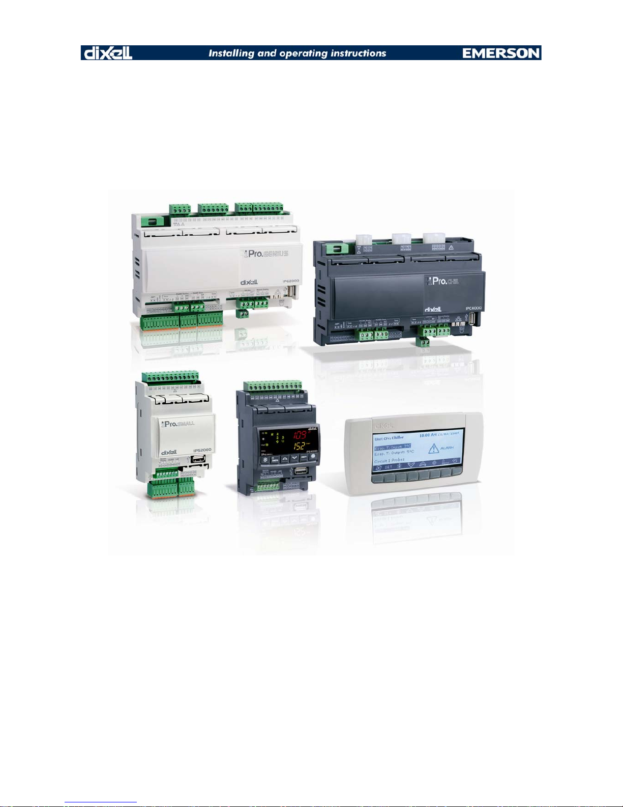
4. VERSIONS OF THE PROGRAMMABLE CONTROLLERS
10 DIN versions:
• IPRO.GENIUS
o IPG115D (15 relays, no application, disconnectable connectors)
o IPG215D (15 relays, no application, spring connectors)
• IPRO.CHILL
o IPC115D (15 relays, with application chiller/heatpump, disconnectable connectors )
o IPC115D SSR (15 relays, with application chiller/heatpump, disconnectable connectors)
• EXPANSION
o IPX125D (25 relay, disconnectable connectors)
o IPX225D (25 relay, spring connectors)
o IPX115D (15 relay, disconnectable connectors)
o IPX215D (15 relay, spring connectors)
4 DIN versions:
• IPRO.GENIUS
o IPG108D (8 relays, no application, disconnectable+screw connectors)
o IPG208D (8 relays, no application, spring+screw connectors)
o IPG108E (8 relays, LED display, without application, diconnectable+screw connectors)
o IPG208E (8 relays, LED display, without application, spring+screw connectors)
• IPRO.CHILL
o IPC108E (8 relays, LED display, with application chiller/heatpump, diconnectable+screw
connectors)
• IPRO.LINK
o IPL500D (connectivity module)
• EXPANSION
o IPX106D (6 relay, disconnectable connectors)
o IPX206D (6 relay, spring+screw connectors)
o IPX306D (6 relay, disconnectable+screw connectors)
• ELECTRONIC VALVE DRIVER
o XEV20D (driver for electronic valve – up to 2 valves per driver)
Page 11
1592025700 IPROFAMILY stp GB 2012.08.08.doc iPro Series 11/72
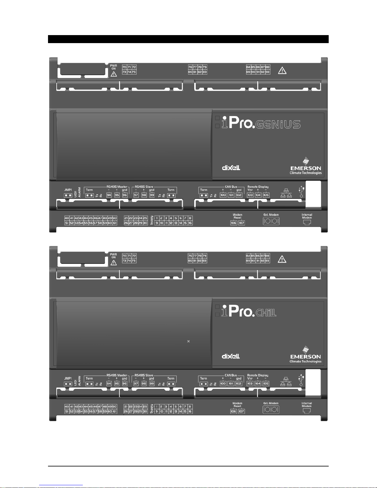
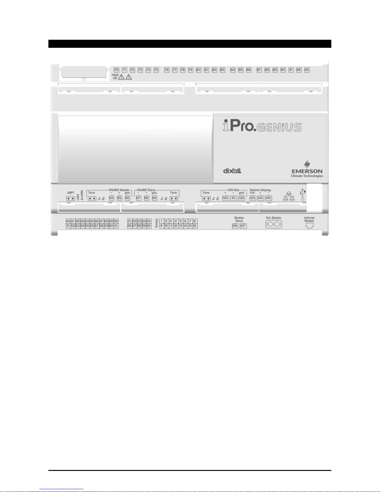
4.1 IPRO.GENIUS AND IPRO.CHILL (IPG100D – IPC100D RANGES)
Page 12
1592025700 IPROFAMILY stp GB 2012.08.08.doc iPro Series 12/72
4.1.1 Description of the connections
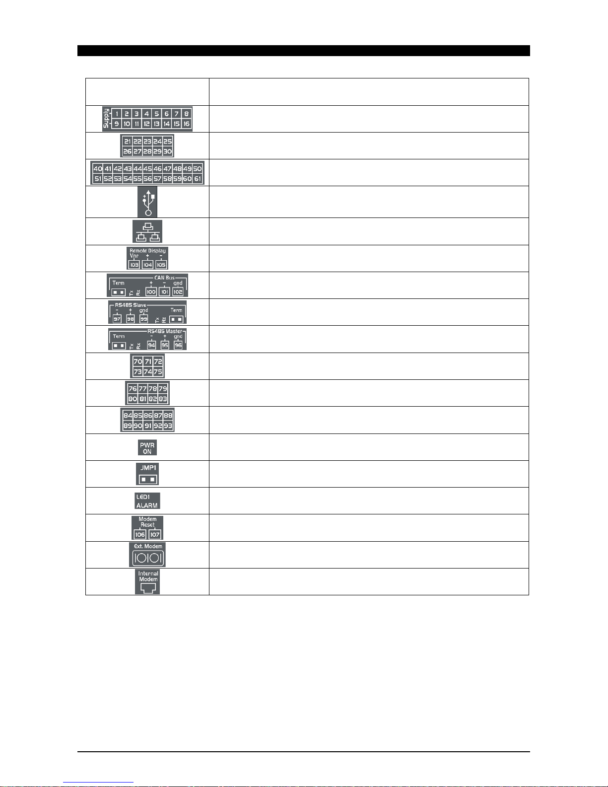
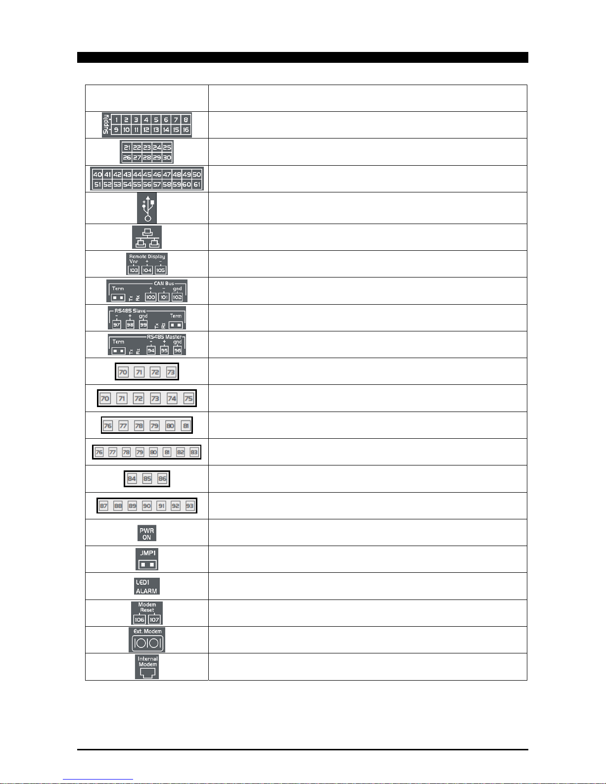
Connector Description
Connector for 24Vac/dc power supply
Analogue inputs (Pb1 - Pb10, PbC)
Additional power (+5Vdc, +12Vdc, GND)
Analogue outputs (Out1 - Out6, TF1 - T2)
Additional power (+12Vdc, GND)
Potential free opto-insulated digital inputs (DI1 - DI20, DIC)
USB port for downloads (BIOS, ISaGRAF® application, maps of parameters, remote display
applications, network configuration, website) and uploads (log files)
TCP/IP Ethernet port
Connector for remote terminal (VISOGRAPH), maximum 2 terminals per iPRO.
CANBUS connector for expansions (IPEXx0D) and drivers for electronic valves (XEVx0D
Rx and Tx LED to indicate that communication is active
Closed circuit terminal (Term)
RS485 Slave connector
Rx and Tx LED to indicate that communication is active
Closed circuit terminal (Term)
RS485 Master connector
Rx and Tx LED to indicate that communication is active
Closed circuit terminal (Term)
Digital relay outputs (115D, 110D, 415D, 410D versions)
3 NO relays + 1 changeover relay, 1 common
Digital relay outputs (115D, 110D, 415D, 410D versions)
6 NO relays, 2 common
Digital relay outputs (only for 115D and 415D versions)
3 NO relays + 2 changeover relays, 3 common (for 115D and 415D versions)
5 relays SSR (for 415D SSR version) *** different connection ***
Green LED to indicate the presence of power
Jumper to activate the RESCUE MODE
Yellow status LEDs (LED1) and red LED (ALARM)
See relative paragraph
Connector for NC contact to reset an external modem
RS232 connector for an external GSM modem connection (SIEMENS TC35)
Connector for an internal analogue modem
Page 13

1592025700 IPROFAMILY stp GB 2012.08.08.doc iPro Series 13/72
4.1.2 Description of the inputs and outputs
Input
No.
Type of Input Description
1 Supply Reference “-“/GND power (24Vac or 24Vdc)
2 Pb1 Configurable analogue input 1 (NTC, PTC, 0 - 20mA, 4 - 20mA, 0 - 10V, 0 - 1V, 0 - 5V, DI)
3 Pb2 Configurable analogue input 2 (NTC, PTC, 0 - 20mA, 4 - 20mA, 0 - 10V, 0 - 1V, 0 - 5V, DI)
4 Pb3 Configurable analogue input 3 (NTC, PTC, 0 - 20mA, 4 - 20mA, 0 - 10V, 0 - 1V, 0 - 5V, DI)
5 Pb4 Configurable analogue input 4 (NTC, PTC, 0 - 20mA, 4 - 20mA, 0 - 10V, 0 - 1V, 0 - 5V, DI)
6 Pb5 Configurable analogue input 5 (NTC, PTC, 0 - 20mA, 4 - 20mA, 0 - 10V, 0 - 1V, 0 - 5V, DI)
7 PbC Common analogue inputs (NTC, PTC, DI)
8 GND (-)
Additional power reference 5Vdc and 12Vdc and analogue inputs (0 - 20mA, 4 - 20mA, 0 - 10V,
0 - 1V, 0 - 5V)
9 Supply Reference “+“ power supply (24Vac or 24Vdc)
10 Pb6 Configurable analogue input 6 (NTC, PTC, 0 - 20mA, 4 - 20mA, 0 - 10V, 0 - 1V, 0 - 5V, DI)
11 Pb7 Configurable analogue input 7 (NTC, PTC, 0 - 20mA, 4 - 20mA, 0 - 10V, 0 - 1V, 0 - 5V, DI)
12 Pb8 Configurable analogue input 8 (NTC, PTC, 0 - 20mA, 4 - 20mA, 0 - 10V, 0 - 1V, 0 - 5V, DI)
13 Pb9 Configurable analogue input 9 (NTC, PTC, 0 - 20mA, 4 - 20mA, 0 - 10V, 0 - 1V, 0 - 5V, DI)
14 Pb10 Configurable analogue input 10 (NTC, PTC, 0 - 20mA, 4 - 20mA, 0 - 10V, 0 - 1V, 0 - 5V, DI)
15 +5V Additional power +5Vdc
16 +12V Additional power +12Vdc
21 Out1 Analogue output 1 0 - 10V
22 Out2 Analogue output 2 0 - 10V
23 Out3 Analogue output 3 0 - 10V
24 Out4 Analogue output 4 0 - 10V
25 GND(-) Additional power reference 12Vdc and analogue outputs
26 Out5 Analogue output 5 0 - 10V, 4 - 20mA, Relay (if TF1 is not used)
27 Out6 Analogue output 6 0 - 10V, 4 - 20mA, Relay (if TF2 is not used)
28 TF1 Analogue output TF1 PWM (if Out5 is not used)
29 TF2 Analogue output TF2 PWM (if Out6 is not used)
30 +12V Additional power +12Vdc
40 DI1 Opto-insulated digital input 1 (potential free contact)
41 DI2 Opto-insulated digital input 2 (potential free contact)
42 DI3 Opto-insulated digital input 3 (potential free contact)
43 DI4 Opto-insulated digital input 4 (potential free contact)
44 DI5 Opto-insulated digital input 5 (potential free contact)
45 DI6 Opto-insulated digital input 6 (potential free contact)
46 DI7 Opto-insulated digital input 7 (potential free contact)
47 DI8 Opto-insulated digital input 8 (potential free contact)
48 DI9 Opto-insulated digital input 9 (potential free contact)
49 DI10 Opto-insulated digital input 10 (potential free contact)
50 DIC Common opto-insulated digital inputs 1 to 20
51 DI11 Opto-insulated digital input 11 (potential free contact)
52 DI12 Opto-insulated digital input 12 (potential free contact)
53 DI13 Opto-insulated digital input 13 (potential free contact)
54 DI14 Opto-insulated digital input 14 (potential free contact)
55 DI15 Opto-insulated digital input 15 (potential free contact)
56 DI16 Opto-insulated digital input 16 (potential free contact)
57 DI17 Opto-insulated digital input 17 (potential free contact)
Page 14

1592025700 IPROFAMILY stp GB 2012.08.08.doc iPro Series 14/72
58 DI18 Opto-insulated digital input 18 (potential free contact)
59 DI19 Opto-insulated digital input 19 (potential free contact)
60 DI20 Opto-insulated digital input 20 (potential free contact)
61 DIC Common digital inputs 1 to 20
70 RL1 Relay 1 normally open contact
71 RL2 Relay 2 normally open contact
72 RL3 Relay 3 normally open contact
73 C Common relays 1, 2, 3 and 4 (MAX 6A)
74 RL4 Relay 4 normally open contact
75 RL3 Relay 3 normally closed contact
76 C Common relays 5, 8 and 9 (MAX 6A)
77 RL5 Relay 5 normally open contact
78 RL6 Relay 6 normally open contact
79 RL7 Relay 7 normally open contact
80 RL8 Relay 8 normally open contact
81 RL9 Relay 9 normally open contact
82 RL10 Relay 10 normally open contact
83 C Common relays 6, 7 and 10 (MAX 6A)
84 RL11 Relay 11 normally open contact
85 RL12 Relay 12 normally open contact
86 RL13 Relay 13 normally open contact
87 C Common relays 12, 13 and 15 (MAX 6A)
88 C Common relays 12, 13 and 15 (MAX 6A)
89 RL11 Relay 11 normally closed contact
90 C Common relays 11 and 14 (MAX 6A)
91 RL14 Relay 14 normally open contact
92 RL14 Relay 14 normally closed contact
93 RL15 Relay 15 normally open contact
94 RS485 Master RS485 Master connection (-)
95 RS485 Master RS485 Master connection (+)
96 RS485 Master RS485 Master connection (insulated gnd)
97 RS485 Slave RS485 Slave connection (-)
98 RS485 Slave RS485 Slave connection (+)
99 RS485 Slave RS485 Slave connection (insulated gnd)
100 CAN Bus CAN Bus connection (+), not open
101 CAN Bus CAN Bus connection (-), not open
102 CAN Bus CAN Bus connection (insulated gnd), not open
103 Remote Display Connection for VISOGRAPH remote terminal (Vnr)
104 Remote Display Connection for VISOGRAPH remote terminal (+)
105 Remote Display Connection for VISOGRAPH remote terminal (-)
106 Modem Reset NC relay input to reset an external modem (24Vac/dc)
107 Modem Reset NC relay output to reset an external modem (24Vac/dc)
Version with SSR relay
84 RL11 Relay 11 normally open contact
85 RL11 Common relays 11
86 RL12 Relay 12 normally open contact
87 RL12 Common relays 12
88 RL13 Common relays 13
Page 15

1592025700 IPROFAMILY stp GB 2012.08.08.doc iPro Series 15/72
89 RL14 Relay 14 normally open contact
90 RL14 Common relays 14
91 RL15 Relay 15 normally open contact
92 RL15 Common relays 15
93 RL13 Relay 13 normally open contact
Page 16
1592025700 IPROFAMILY stp GB 2012.08.08.doc iPro Series 16/72
4.1.3 Technical specifications
4.1.3.1 Analogue inputs
Analogue conversion type: 10-bit A/D converter
Number of inputs: 10
Type of analogue input:
(configurable via software parameter)
NTC Dixell (-50T110°C; 10KΩ±1% at 25°C)
PTC Dixell(-55T115°C; 990Ω±1% at 25°C)
Digital input (potential free contact)
Voltage: 0 - V, 0 - 5V, 0 - 10V (input resistance 3.7KΩ )
Current: 0 - 20mA, 4 - 20mA (input resistance 100Ω)
Digital input status variation detection time: 100ms (in any case it depends on the cycle time set by the user in the
given application)
Accuracy: NTC, PTC: ±1°C
0-1V: ±20mV
0-5V: ±100mV
0-10V: ±200mV
2-20mA, 4-20mA: ±0.30mA
Additional power: +12V: 200mA in total (between +12V and analogue outputs)
+5v: 100mA
Notes: Any inputs that are powered with a voltage that differs from that supplied
by the device (+12V or +5V) must be powered separately with another
transformer (do not use the same secondary of the controller's power) in
order to prevent the inputs from malfunctioning or being damaged.
4.1.3.2 Digital inputs
Type:
(configurable via software parameter)
Opto-insulated potential free contact
Number of inputs: 20
Digital input status variation detection time: 100ms (in any case it depends on the cycle time set by the user in the
given application)
Notes: Do not use live contacts in order to prevent the inputs from being
damaged.
4.1.3.3 Analogue outputs
Type: Non opto-insulated internal power
Number of outputs: 6
Type of analogue output:
(configurable via software parameter)
4 fixed outputs 0-10Vdc (Out1 - Out4)
2 configurable outputs (alternative):
- 0-10Vdc, 4-20mA (Out5 and Out6)
- PWM to be used with Dixell XV modules (TF1 and TF2)
Maximum load: 40mA (Out1 - Out4)
20mA (Out5 and Out6) max with configured outputs 0-10Vdc
400Ω max with configured outputs 4-20mA
22Ω per live analogue output
Accuracy: Out1 - Out4: ±2% full scale
Out5 – Out6: ±2% full scale
Resolution: 8bit
Notes: The electrical devices controlled by these analogue outputs must be
powered separately with another transformer (do not use the same
secondary of the controller's power) in order to prevent the outputs from
malfunctioning or being damaged.
Page 17
1592025700 IPROFAMILY stp GB 2012.08.08.doc iPro Series 17/72
4.1.3.4 Standard Digital outputs
Type: Relays with NO or NC contacts, depending on the model
Number of outputs: 10 or 15, depending on the model
Type of output:
(configurable via software parameter)
Relays with normally open contact:
- RL1, RL2, RL4, RL5, RL6, RL7, RL8, RL9, RL10, RL12, RL13, RL15
Relays with changeover contact:
- RL3, RL11, RL14
Maximum load: Relays with normally open contact: 5A(250Vac) SPST 5(2)A
Relays with changeover contact: 8A(250Vac) SPDT 8(3)A
Notes: Verify the capacity of the output used. There is double insulation between
the digital outputs and the low voltage of the rest of the circuit.
Do not use different voltages for the various groups of relays nor within
each group.
4.1.3.5 SSR Digital outputs version
Type: Relays with NO or NC contacts, depending on the model
Number of outputs: 10 or 15, depending on the model
Type of output:
(configurable via software parameter)
Relays with normally open contact:
- RL1, RL2, RL4, RL5, RL6, RL7, RL8, RL9, RL10, RL11, RL12, RL13,
RL14, RL15
Relays with changeover contact:
- RL3
Maximum load: Relays with normally open contact: 5A(250Vac) SPST 5(2)A
Relays with changeover contact: 8A(250Vac) SPDT 8(3)A
SSR relays with normally open contact 1A(12 - 250Vac):
- only in AC load
- minimum current is 50mA (equivalent to 12W - 250Vac)
- internal impedance 300KΩ (current 0.2mA at 250Vac with an open
contact)
Notes: Verify the capacity of the output used. There is double insulation between
the digital outputs and the low voltage of the rest of the circuit.
Do not use different voltages for the various groups of relays nor within
each group.
Page 18
1592025700 IPROFAMILY stp GB 2012.08.08.doc iPro Series 18/72
4.1.3.6 Wiring diagrams
Page 19
1592025700 IPROFAMILY stp GB 2012.08.08.doc iPro Series 19/72
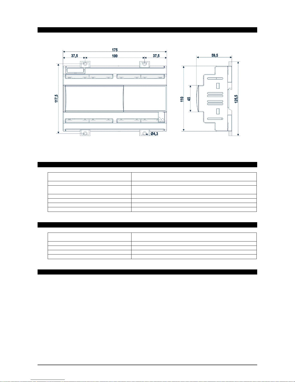
4.1.3.7 Mechanical specifications
10 DIN module
4.1.3.8 Electrical specifications
Power Supply: 24Vac +10/-15%, 50/60Hz
20 - 36Vdc
Consumption: 20VA (Vac), 15W (Vdc)
Connectors: Molex connectors with low voltage wiring
SELECOM/CIVILUX connectors for digital outputs (250Vac, 6A max)
Microprocessor: AT91RM9200 32-bit 200Mhz
Permanent FLASH memory: 128MB, in 8-bit
RAM: 32MB or 64MB, in 16-bit
Internal clock: standard
4.1.3.9 Plastic container
Mount: On a DIN rail (EN 50022, DIN 43880)
Fastened with screws via the removable plastic flaps.
Material: PC-ABS Thermoplastic
Self-extinguishing: V0 (UL94)
Comparative Tracking Index (CTI): 300V
Colour: Black
4.1.3.10 Product certifications
Control to classify with the definitions 2.5.1 e 2.5.2 mentioned in the section 2.5 of the general
requirements EN60730-1 (2.5.1 = integrated control, 2.5.2 = incorporated control).
Electrical safety:
• EN60730-1
Electromagnetic compatibility:
• EN61000-4-2, EN61000-4-3, EN61000-4-4, EN61000-4-5, EN61000-4-6, EN61000-4-8,
EN61000-4-11
Page 20
1592025700 IPROFAMILY stp GB 2012.08.08.doc iPro Series 20/72
4.2 IPRO.GENIUS (IPG200D RANGE)
Page 21
1592025700 IPROFAMILY stp GB 2012.08.08.doc iPro Series 21/72
4.2.1 Description of the connections
Connector Description
Connector for 24Vac/dc power supply
Analogue inputs (Pb1 - Pb10, PbC)
Additional power (+5Vdc, +12Vdc, GND)
Opto-insulated analogue outputs (Out1 - Out6, GND)
24Vac/dc power supply for the opto-insulated analogue output
Potential free opto-insulated digital inputs (DI1 - DI20, DIC)
Opto-insulated 24Vac/dc digital inputs (DI1 - DI20, GND)
USB port for downloads (BIOS, ISaGRAF® application, maps of parameters, remote display
applications, network configuration, website) and uploads (log files)
TCP/IP Ethernet port
Connector for remote terminal (VISOGRAPH), maximum 2 terminals per iPRO.
CANBUS connector for expansions (IPEXx0D) and drivers for electronic valves (XEVx0D
Rx and Tx LED to indicate that communication is active
Closed circuit terminal (Term)
RS485 Slave connector
Rx and Tx LED to indicate that communication is active
Closed circuit terminal (Term)
RS485 Master connector
Rx and Tx LED to indicate that communication is active
Closed circuit terminal (Term)
Digital relay outputs (for digital outputs with potential free contacts)
3 NO relays, 1 common
Digital relay outputs (for digital outputs with live contacts)
3 NO relays, 1 common and 2 potential free (Neutral)
Digital relay outputs (for digital outputs with potential free contacts)
5 NO relays, 1 common
Digital relay outputs (for digital outputs with live contacts)
5 NO relays, 1 common and 2 potential free (Neutral)
Digital relay outputs
2 NO relays, 1 common
Digital relay outputs (only for 215D versions)
5 NO relays, 1 common and 1 potential free (Neutral)
Green LED to indicate the presence of power
Jumper to activate the RESCUE MODE
Yellow status LEDs (LED1) and red LED (ALARM)
See relative paragraph
Connector for NC contact to reset an external modem
RS232 connector for an external GSM modem connection (SIEMENS TC35)
Connector for an internal analogue modem
Page 22

1592025700 IPROFAMILY stp GB 2012.08.08.doc iPro Series 22/72
4.2.2 Description of the inputs and outputs
Input
No.
Type of Input Description
1 Supply Reference “-“/GND power (24Vac or 24Vdc)
2 Pb1 Configurable analogue input 1 (NTC, PTC, 0 - 20mA, 4 - 20mA, 0 - 10V, 0 - 1V, 0 - 5V, DI)
3 Pb2 Configurable analogue input 2 (NTC, PTC, 0 - 20mA, 4 - 20mA, 0 - 10V, 0 - 1V, 0 - 5V, DI)
4 Pb3 Configurable analogue input 3 (NTC, PTC, 0 - 20mA, 4 - 20mA, 0 - 10V, 0 - 1V, 0 - 5V, DI)
5 Pb4 Configurable analogue input 4 (NTC, PTC, 0 - 20mA, 4 - 20mA, 0 - 10V, 0 - 1V, 0 - 5V, DI)
6 Pb5 Configurable analogue input 5 (NTC, PTC, 0 - 20mA, 4 - 20mA, 0 - 10V, 0 - 1V, 0 - 5V, DI)
7 PbC Common analogue inputs (NTC, PTC, DI)
8 GND(-)
Additional power reference 5Vdc and 12Vdc and analogue inputs (0 - 20mA, 4 - 20mA, 0 10V, 0 - 1V, 0 - 5V)
9 Supply Reference “+“ power supply (24Vac or 24Vdc)
10 Pb6 Configurable analogue input 6 (NTC, PTC, 0 - 20mA, 4 - 20mA, 0 - 10V, 0 - 1V, 0 - 5V, DI)
11 Pb7 Configurable analogue input 7 (NTC, PTC, 0 - 20mA, 4 - 20mA, 0 - 10V, 0 - 1V, 0 - 5V, DI)
12 Pb8 Configurable analogue input 8 (NTC, PTC, 0 - 20mA, 4 - 20mA, 0 - 10V, 0 - 1V, 0 - 5V, DI)
13 Pb9 Configurable analogue input 9 (NTC, PTC, 0 - 20mA, 4 - 20mA, 0 - 10V, 0 - 1V, 0 - 5V, DI)
14 Pb10 Configurable analogue input 10 (NTC, PTC, 0 - 20mA, 4 - 20mA, 0 - 10V, 0 - 1V, 0 - 5V, DI)
15 +5V Additional power +5Vdc
16 +12V Additional power +12Vdc
21 Out1 Opto-insulated analogue output 1 0 - 10V
22 Out2 Opto-insulated analogue output 2 0 - 10V
23 Out3 Opto-insulated analogue output 3 0 - 10V
24 Out4 Opto-insulated analogue output 4 0 - 10V
25 GND(-) Common opto-insulated analogue output
26 Out5 Analogue output 5 0 - 10V, 4 - 20mA, Opto-insulated relay
27 Out6 Analogue output 6 0 - 10V, 4 - 20mA, Opto-insulated relay
28 Supply Power for opto-insulated analogue outputs at 24Vac or 24Vdc(-)
29 Supply Power for opto-insulated analogue outputs at 24Vac or 24Vdc(+)
30 GND(-) Common opto-insulated analogue output
40 DI1 Opto-insulated digital input 1
41 DI2 Opto-insulated digital input 2
42 DI3 Opto-insulated digital input 3
43 DI4 Opto-insulated digital input 4
44 DI5 Opto-insulated digital input 5
45 DI6 Opto-insulated digital input 6
46 DI7 Opto-insulated digital input 7
47 DI8 Opto-insulated digital input 8
48 DI9 Opto-insulated digital input 9
49 DI10 Opto-insulated digital input 10
50 GND(-) Reference “-“ for opto-insulated digital inputs 1 to 20 (if inputs 24Vac or 24Vdc)
51 DI11 Opto-insulated digital input 11
52 DI12 Opto-insulated digital input 12
53 DI13 Opto-insulated digital input 13
54 DI14 Opto-insulated digital input 14
55 DI15 Opto-insulated digital input 15
56 DI16 Opto-insulated digital input 16
57 DI17 Opto-insulated digital input 17
58 DI18 Opto-insulated digital input 18
Page 23

1592025700 IPROFAMILY stp GB 2012.08.08.doc iPro Series 23/72
59 DI19 Opto-insulated digital input 19
60 DI20 Opto-insulated digital input 20
61 IDC Common opto-insulated digital inputs 1 to 20 (if potential free inputs)
70 RL1 Relay 1 normally open contact
71 C Common relays 1, 2 and 3 (MAX 6A)
72 RL2 Relay 2 normally open contact
73 RL3 Relay 3 normally open contact
74 C Potential free contact (MAX 6A)
75 C Potential free contact (MAX 6A)
76 RL4 Relay 4 normally open contact
77 RL5 Relay 5 normally open contact
78 RL6 Relay 6 normally open contact
79 RL7 Relay 7 normally open contact
80 C Common relays 4, 5, 6, 7 and 8 (MAX 6A)
81 RL8 Relay 8 normally open contact
82 C Potential free contact (MAX 6A)
83 C Potential free contact (MAX 6A)
84 RL9 Relay 9 normally open contact
85 RL10 Relay 10 normally open contact
86 C Common relays 9 and 10 (MAX 6A)
87 RL11 Relay 11 normally open contact
88 RL12 Relay 12 normally open contact
89 RL13 Relay 13 normally open contact
90 C Common relays 11, 12, 13, 14 and 15 (MAX 6A)
91 RL14 Relay 14 normally open contact
92 RL15 Relay 15 normally open contact
93 C Potential free contact (MAX 6A)
94 RS485 Master RS485 Master connection (-)
95 RS485 Master RS485 Master connection (+)
96 RS485 Master RS485 Master connection (insulated gnd)
97 RS485 Slave RS485 Slave connection (-)
98 RS485 Slave RS485 Slave connection (+)
99 RS485 Slave RS485 Slave connection (insulated gnd)
100 CAN Bus CAN Bus connection (+), not open
101 CAN Bus CAN Bus connection (-), not open
102 CAN Bus CAN Bus connection (insulated gnd), not open
103 Remote Display Connection for VISOGRAPH remote terminal (Vnr)
104 Remote Display Connection for VISOGRAPH remote terminal (+)
105 Remote Display Connection for VISOGRAPH remote terminal (-)
106 Modem Reset NC relay input to reset an external modem (24Vac/dc)
107 Modem Reset NC relay output to reset an external modem (24Vac/dc)
Page 24

1592025700 IPROFAMILY stp GB 2012.08.08.doc iPro Series 24/72
4.2.3 Technical specifications
4.2.3.1 Analogue inputs
Analogue conversion type: 10-bit A/D converter
Number of inputs: 10
Type of analogue input:
(configurable via software parameter)
NTC Dixell (-50T110°C; 10KΩ±1% at 25°C)
PTC Dixell(-55T115°C; 990Ω±1% at 25°C)
Digital input (potential free contact)
Voltage: 0 - V, 0 - 5V, 0 - 10V (input resistance 3.7KΩ )
Current: 0 - 20mA, 4 - 20mA (input resistance 100Ω)
Digital input status variation detection time: 100ms (in any case it depends on the cycle time set by the user in the
given application)
Accuracy: NTC, PTC: ±1
0-1V: ±20mV
0-5V: ±100mV
0-10V:±200mV
2-20mA, 4-20mA: ±0.30mA
Additional power: +12V: 200mA in total
+5v: 100mA
Notes: Any inputs that are powered with a voltage that differs from that supplied
by the device (+12V or +5V) must be powered separately with another
transformer (do not use the same secondary of the controller's power) in
order to prevent the inputs from malfunctioning or being damaged.
4.2.3.2 Digital inputs
Type:
(configurable via software parameter)
Opto-insulated potential free or live contact (24Vac/dc)
External power 24Vac/dc ±20%
Number of inputs: 20
Digital input status variation detection time: 100ms (in any case it depends on the cycle time set by the user in the
given application)
Notes:
If the digital inputs are used with voltage, use another transformer (do not
use the same secondary of the controller's power) in order to prevent the
inputs from malfunctioning or being damaged.
4.2.3.3 Analogue outputs
Type: Opto-insulated with separate 24Vac/dc power supply
Number of outputs: 6
Type of analogue output:
(configurable via software parameter)
4 fixed outputs 0-10Vdc (Out1 - Out4)
2 configurable outputs 0-10Vdc, 4-20mA (Out5 and Out6)
Maximum load: 40mA (Out1 - Out4)
20mA (Out5 and Out6) max with configured outputs 0-10Vdc
400Ω max with configured outputs 4-20Ma
22Ω per live analogue output
Accuracy: Out1 - Out4: ±2% full scale
Out5 – Out6: ±2% full scale
Resolution: 8bit
Notes: The electrical devices controlled by these analogue outputs must be
powered separately with another transformer (do not use the same
secondary of the controller's power) in order to prevent the outputs from
malfunctioning or being damaged.
4.2.3.4 Digital outputs
Type: Relays with NO contacts
Number of outputs: 10 or 15, depending on the model
Type of output:
(configurable via software parameter)
Relays with normally open contact
Maximum load: 5A(250Vac) SPST 5(2)A
Notes: Verify the capacity of the output used. There is double insulation between
the digital outputs and the low voltage of the rest of the circuit.
Do not use different voltages for the various groups of relays nor within
each group.
Page 25

1592025700 IPROFAMILY stp GB 2012.08.08.doc iPro Series 25/72
4.2.3.5 Wiring diagrams
4.2.3.6 Mechanical specifications
10 DIN module
4.2.3.7 Electrical specifications
Power Supply: 24Vac +10/-15%, 50/60Hz
20 - 36Vdc
Consumption: 20VA (Vac), 15W (Vdc)
Connectors: Phoenix quick coupling connectors for low voltage
STELVIO 90° screw connectors for digital outputs (250Vac, 6A max)
Microprocessor: AT91RM9200 32-bit 200Mhz
Permanent FLASH memory: 128MB, in 8-bit
RAM: 32MB o 64MB, in 16-bit
Internal clock: standard
Page 26

1592025700 IPROFAMILY stp GB 2012.08.08.doc iPro Series 26/72
4.2.3.8 Plastic container
Mount: On a DIN rail (EN 50022, DIN 43880)
Fastened with screws via the removable plastic flaps.
Material: PC-ABS Thermoplastic
Self-extinguishing: V0 (UL94)
Comparative Tracking Index (CTI): 300V
Colour: White
4.2.3.9 Product certifications
Control to classify with the definitions 2.5.1 e 2.5.2 mentioned in the section 2.5 of the general
requirements EN60730-1 (2.5.1 = integrated control, 2.5.2 = incorporated control).
Electrical safety:
• EN60730-1
Electromagnetic compatibility:
• EN61000-4-2, EN61000-4-3, EN61000-4-4, EN61000-4-5, EN61000-4-6, EN61000-4-8,
EN61000-4-11
Page 27

1592025700 IPROFAMILY stp GB 2012.08.08.doc iPro Series 27/72
4.3 IPRO 4 DIN (IPG100D – IPG200D – IPC100E RANGES)
4.3.1 Description of the connections
Connector Description
Connector for 24Vac/dc power supply
Analogue inputs (Pb1 - Pb6, PbC)
Additional power (+5Vdc, +12Vdc, GND)
Analogue outputs (Out1 - Out4, GND)
Page 28

1592025700 IPROFAMILY stp GB 2012.08.08.doc iPro Series 28/72
24Vac/dc digital inputs (DI1 - DI11, GND)
Connector for remote terminal (VISOGRAPH), maximum 1 terminal per iPRO.
RS485 Slave connector
Serial port connector (LAN or RS485)
USB port for downloads (BIOS, ISaGRAF® application, maps of parameters, remote display
applications, network configuration, website) and uploads (log files)
Connection with the computer via a USB-ETH converter
Digital relay outputs
4 NO relays, 2 common
Digital relay outputs
4 NO relays, 2 common
4.3.2 Description of the inputs and outputs
Input
No.
Type of Input Description
1 Supply Reference “-“/GND power (24Vac or 24Vdc)
2 Pb1 Configurable analogue input 1 (NTC, PTC, 0 - 20mA, 4 - 20mA, 0 - 10V, 0 - 1V, 0 - 5V, DI)
3 Pb2 Configurable analogue input 2 (NTC, PTC, 0 - 20mA, 4 - 20mA, 0 - 10V, 0 - 1V, 0 - 5V, DI)
4 Pb3 Configurable analogue input 3 (NTC, PTC, 0 - 20mA, 4 - 20mA, 0 - 10V, 0 - 1V, 0 - 5V, DI)
5 +12V Additional power +12Vdc
6 +5V Additional power +5Vdc
7 Out1 Analogue output 1 0 - 10V, 4 - 20mA, Relay
8 Out2 Analogue output 2 0 - 10V, 4 - 20mA, Relay
9 Supply Reference “+“ power supply (24Vac or 24Vdc)
10 Pb4 Configurable analogue input 4 (NTC, PTC, 0 - 20mA, 4 - 20mA, 0 - 10V, 0 - 1V, 0 - 5V, DI)
11 Pb5 Configurable analogue input 5 (NTC, PTC, 0 - 20mA, 4 - 20mA, 0 - 10V, 0 - 1V, 0 - 5V, DI)
12 Pb6 Configurable analogue input 6 (NTC, PTC, 0 - 20mA, 4 - 20mA, 0 - 10V, 0 - 1V, 0 - 5V, DI)
13 PbC Common analogue inputs (NTC, PTC, DI)
14 GND(-)
Additional power reference 5Vdc and 12Vdc, analogue inputs (0 - 20mA, 4 - 20mA, 0 - 10V, 0
- 1V, 0 - 5V), analogue outputs
15 Out3 Analogue output 3 0 - 10V, 4 - 20mA, Relay
16 Out4 Analogue output 4 0 - 10V, 4 - 20mA, Relay
20 DI1 Digital input 1 24Vac/dc
21 DI2 Digital input 2 24Vac/dc
22 DI3 Digital input 3 24Vac/dc
23 DI4 Digital input 4 24Vac/dc
24 DI5 Digital input 5 24Vac/dc
25 DI6 Digital input 6 24Vac/dc
26 DI7 Digital input 7 24Vac/dc
27 DI8 Digital input 8 24Vac/dc
28 DI9 Digital input 9 24Vac/dc
29 DI10 Digital input 10 24Vac/dc
30 DI11 Digital input 11 24Vac/dc
31 GND(-)
Reference “-“ for digital inputs from1 to 11 (if version with dry contacts, this input has
to be used only as common for the digital inputs)
40 C Common relays 1, 2, 3 and 4 (MAX 10A)
41 C Common relays 1, 2, 3 and 4 (MAX 10A)
42 RL1 Relay 1 normally open contact
43 RL2 Relay 2 normally open contact
Page 29

1592025700 IPROFAMILY stp GB 2012.08.08.doc iPro Series 29/72
44 RL3 Relay 3 normally open contact
45 RL4 Relay 4 normally open contact
46 RL5 Relay 5 normally open contact
47 C Common relays 5, 6, 7 and 8 (MAX 10A)
48 C Common relays 5, 6, 7 and 8 (MAX 10A)
49 RL6 Relay 6 normally open contact
50 RL7 Relay 7 normally open contact
51 RL8 Relay 8 normally open contact
60 Remote Display Connection for VISOGRAPH remote terminal (Vnr)
61 Remote Display Connection for VISOGRAPH remote terminal (+)
62 Remote Display Connection for VISOGRAPH remote terminal (-)
63 RS485 Slave RS485 Slave connection (-)
64 RS485 Slave RS485 Slave connection (+)
65 LAN LAN Connection (-)
66 LAN LAN Connection (+)
4.3.3 Technical specifications
4.3.3.1 Analogue inputs
Analogue conversion type: 10-bit A/D converter
Number of inputs: 6
Type of analogue input:
(configurable via software parameter)
NTC Dixell (-50T110°C; 10KΩ±1% at 25°C)
PTC Dixell(-55T115°C; 990Ω±1% at 25°C)
Digital input (potential free contact)
Voltage: 0 - V, 0 - 5V, 0 - 10V (input resistance 3.7KΩ )
Current: 0 - 20mA, 4 - 20mA (input resistance 100Ω)
Digital input status variation detection time: 100ms (in any case it depends on the cycle time set by the user in the
given application)
Accuracy: NTC, PTC: ±1
0-1V: ±20mV
0-5V: ±100mV
0-10V:±200mV
2-20mA, 4-20mA: ±0.30mA
Additional power: +12V: 200mA in total (between +12V and analogue outputs)
+5v: 100mA
Notes: Any inputs that are powered with a voltage that differs from that supplied
by the device (+12V or +5V) must be powered separately with another
transformer (do not use the same secondary of the controller's power) in
order to prevent the inputs from malfunctioning or being damaged.
4.3.3.2 Digital inputs
Type:
(configurable via software parameter)
Opto-insulated live contact (24Vac/dc)
External power 24Vac/dc ±20%
Number of inputs: 11
Digital input status variation detection time: 100ms (in any case it depends on the cycle time set by the user in the
given application)
Notes: Use another transformer (do not use the same secondary of the
controller's power) in order to prevent the inputs from malfunctioning or
being damaged.
Note: the digital inputs as dry contacts are available on request.
Page 30

1592025700 IPROFAMILY stp GB 2012.08.08.doc iPro Series 30/72
4.3.3.3 Analogue outputs
Type: Non opto-insulated internal power
Number of outputs: 4
Type of analogue output:
(configurable via software parameter)
4 configurable outputs 0-10Vdc 4-20mA (Out1 - Out4)
Maximum load: 40mA (Out1 - Out4) max with configured outputs 0-10Vdc
400Ω max with configured outputs 4-20mA
22Ω per live analogue output
Accuracy: Out1 - Out4: ±2% full scale
Resolution: 8bit
Notes: The electrical devices controlled by these analogue outputs must be
powered separately with another transformer (do not use the same
secondary of the controller's power) in order to prevent the outputs from
malfunctioning or being damaged.
4.3.3.4 Digital outputs
Type: Relays with NO contacts
Number of outputs: 8
Type of output:
(configurable via software parameter)
Relays with normally open contact
Maximum load: 5A(250Vac) SPST 5(2)A
Notes: Verify the capacity of the output used. There is double insulation between
the digital outputs and the low voltage of the rest of the circuit.
Do not use different voltages for the various groups of relays nor within
each group.
4.3.3.5 Wiring diagrams
Page 31

1592025700 IPROFAMILY stp GB 2012.08.08.doc iPro Series 31/72
4.3.3.6 Mechanical specifications
4 DIN module
4.3.3.7 Electrical specifications
Power Supply: 24Vac +10/-15%, 50/60Hz
20 - 36Vdc
Consumption: from 30VA (Vac), from 25W (Vdc)
Connectors: Molex connectors with low voltage wiring (for IPS100D and IPS400D)
Phoenix quick coupling connectors for low voltage (for IPS200D)
STELVIO 90° screw connectors for digital outputs (250Vac, 6A max)
Microprocessor: AT91SAM9260 32-bit 200Mhz
Permanent FLASH memory: 32MB, in 8-bit
RAM: 32MB, in 16
Internal clock: standard
4.3.3.8 Plastic container
Mount: On a DIN rail (EN 50022, DIN 43880)
Fastened with screws via the removable plastic flaps.
Material: PC-ABS Thermoplastic
Self-extinguishing: V0 (UL94)
Comparative Tracking Index (CTI): 300V
Colour: Black or White, depending on the model
4.3.3.9 USB-ETHERNET Adapter
The IPS range of programmable controllers can be connected to a computer via an external adapter. This
adapter must be used in the processing environment for the application download in the ipro. This
adapter is not set up for fixed or continuous connection. If the adapter should be kept connected
continuously, the room temperature must not exceed 50°C.
Page 32
1592025700 IPROFAMILY stp GB 2012.08.08.doc iPro Series 32/72
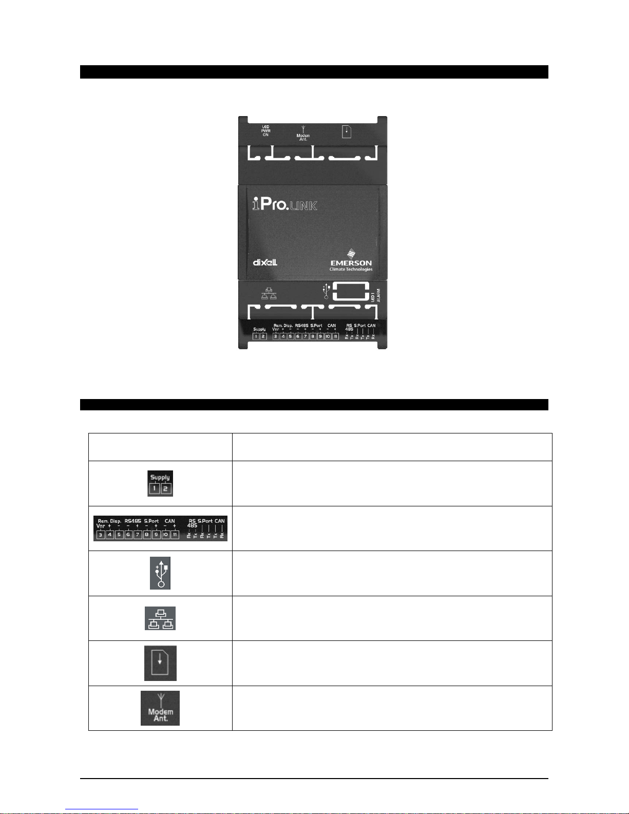
4.4 IPRO.LINK (IPL500D)
4.4.1 Description of the connections
Connector Description
Connector for 24Vac/dc power supply
Connector for remote terminal (VISOGRAPH), maximum 1 terminal per iPRO.
RS485 Slave connector
Serial port connector (LAN or RS485)
CANBUS connector (for expansion and driver for electroni expansion valve)
Communication leds
USB port for downloads (BIOS, ISaGRAF® application, maps of parameters, remote
display applications, network configuration, website) and uploads (log files)
Ethernet port for TCP/IP connections
SIM CARD slot (only for version with GPRS modem)
Connection for GPRS modem antenna
Page 33

1592025700 IPROFAMILY stp GB 2012.08.08.doc iPro Series 33/72
4.4.2 Description of the inputs and outputs
Input
No.
Type of Input Description
1 Supply Reference “-“/GND power (24Vac or 24Vdc)
2 Supply Reference “+“ power supply (24Vac or 24Vdc)
3 Remote Display Connection for VISOGRAPH remote terminal (Vnr)
4 Remote Display Connection for VISOGRAPH remote terminal (+)
5 Remote Display Connection for VISOGRAPH remote terminal (-)
6 RS485 Slave RS485 Slave connection (-)
7 RS485 Slave RS485 Slave connection (+)
8 Serial Port LAN or RS485 MASTER Connection (-) – depend on the model
9 Serial Port LAN or RS485 MASTER Connection (+) – depend on the model
10 CAN CANBUS connection (-)
11 CAN CANBUS connection (+)
4.4.3 Technical specifications
4.4.3.1 Wiring diagrams
Page 34

1592025700 IPROFAMILY stp GB 2012.08.08.doc iPro Series 34/72
4.4.3.2 Mechanical specifications
4 DIN module
4.4.3.3 Electrical specifications
Power Supply: 24Vac +10/-15%, 50/60Hz
20 - 36Vdc
Consumption: from 20VA (Vac), from 15W (Vdc)
Connectors: STELVIO 90° screw connectors for digital outputs (250Vac, 6A max)
Microprocessor: AT91SAM9260 32-bit 200Mhz
Permanent FLASH memory: 128MB, in 8
RAM: 32MB, in 16
Internal clock: standard
4.4.3.4 Plastic container
Mount: On a DIN rail (EN 50022, DIN 43880)
Fastened with screws via the removable plastic flaps.
Material: PC-ABS Thermoplastic
Self-extinguishing: V0 (UL94)
Comparative Tracking Index (CTI): 300V
Colour: Black or White, depending on the model
Page 35

1592025700 IPROFAMILY stp GB 2012.08.08.doc iPro Series 35/72
4.5 IPX106D
4.5.1 Description of the connections
Connector Description
Connector for 24Vac/dc power supply
Analogue inputs (Pb1 - Pb5, PbC)
Potential free digital inputs (DI1 - DI3, DIC)
Additional power (+5Vdc, +12Vdc, GND)
Analogue outputs (Out1..Out3, GND)
Analogue inputs (Pb6 - Pb7, PbC)
Additional power (+5Vdc, +12Vdc, GND)
Digital relay outputs
6 NO relays, 2 common
CANBUS Connector
Rx and Tx LED to indicate that communication is active
Closed circuit terminal (Term)
LAN serial port connector
Dip-switch to set the address of the device.
Green LED to indicate the presence of power
Red status LED (ALARM)
See relative paragraph
Page 36

1592025700 IPROFAMILY stp GB 2012.08.08.doc iPro Series 36/72
4.5.2 Description of the inputs and outputs
Input
No.
Type of Input Description
1 Supply Reference “-“/GND power (24Vac or 24Vdc)
2 Pb1
Configurable analogue input 1 (NTC, PTC, PT1000, 0 - 20mA, 4 - 20mA, 0 - 5V, 0 - 1V, 0 10V, DI, not used)
3 Pb2
Configurable analogue input 1 (NTC, PTC, PT1000, 0 - 20mA, 4 - 20mA, 0 - 5V, 0 - 1V, 0 10V, DI, not used)
4 Pb3
Configurable analogue input 1 (NTC, PTC, PT1000, 0 - 20mA, 4 - 20mA, 0 - 5V, 0 - 1V, 0 10V, DI, not used)
5 Pb4
Configurable analogue input 1 (NTC, PTC, PT1000, 0 - 20mA, 4 - 20mA, 0 - 5V, 0 - 1V, 0 10V, DI, not used)
6 Pb5
Configurable analogue input 1 (NTC, PTC, PT1000, 0 - 20mA, 4 - 20mA, 0 - 5V, 0 - 1V, 0 10V, DI, not used)
7 +12V Additional power +12Vdc
8 +12V Additional power +12Vdc
9 Supply Reference “+“ power supply (24Vac or 24Vdc)
10 DI1 Digital input 1 (potential free contact)
11 DI2 Digital input 2 (potential free contact)
12 DI3 Digital input 3 (potential free contact)
13 DIC Common digital inputs 1 to 3
14 Pbc Common analogue inputs (NTC, PTC, PT1000, DI)
15 GND(-)
Additional power reference 5Vdc and 12Vdc and analogue inputs (0 - 20mA, 4 - 20mA, 0 10V, 0 - 1V, 0 - 5V)
16 +5V Additional power +5Vdc
20 GND(-) Additional power reference 5Vdc, 12Vdc and analogue outputs
21 Out1 Analogue output 1 0 - 10V
22 Out2 Analogue output 2 0 - 10V
23 Out3 Analogue output 3 0 - 10V
24 Pb6
Configurable analogue input 1 (NTC, PTC, PT1000, 0 - 20mA, 4 - 20mA, 0 - 5V, 0 - 1V, 0 10V, DI, not used)
25 GND(-) Additional power reference 5Vdc, 12Vdc and analogue outputs
26 +12V Additional power +12Vdc
27 +5V Additional power +5Vdc
28 Pbc Common analogue inputs (NTC, PTC, PT1000, DI)
29 Pb7
Configurable analogue input 1 (NTC, PTC, PT1000, 0 - 20mA, 4 - 20mA, 0 - 5V, 0 - 1V, 0 10V, DI, not used)
30 CAN Bus CAN Bus connection (+), not open
32 CAN Bus CAN Bus connection (-), not open
33 CAN Bus CAN Bus connection (insulated gnd), not open
40 RL4 Relay 4 normally open contact
41 RL5 Relay 5 normally open contact
42 RL6 Relay 6 normally open contact
43 C Common relays 5, 6 and 3 (MAX 6A)
44 C Common relays 1, 2 and 4 (MAX 6A)
45 RL1 Relay 1 normally open contact
46 RL2 Relay 2 normally closed contact
47 RL3 Relay 3 normally closed contact
Page 37

1592025700 IPROFAMILY stp GB 2012.08.08.doc iPro Series 37/72
4.5.3 Technical specifications
4.5.3.1 Analogue inputs
Analogue conversion type: 10-bit A/D converter
Number of inputs: 7
Type of analogue input:
(configurable via software parameter)
NTC Dixell (-50T110°C; 10KΩ±1% at 25°C)
PTC Dixell(-55T115°C; 990Ω±1% at 25°C)
PT1000 Dixell (-100T150°C; 1KΩ at 0°C)
Digital input (potential free contact)
Voltage: 0 - V, 0 - 5V, 0 - 10V (input resistance 3.7KΩ )
Current: 0 - 20mA, 4 - 20mA (input resistance 100Ω)
Digital input status variation detection time: 100ms (in any case it depends on the cycle time set by the user in the
given application)
Accuracy: NTC, PTC, PT1000: ±1°C
0-1V: ±20mV
0-5V: ±100mV
0-10V:±200mV
2-20mA, 4-20mA: ±0.30mA
Additional power: +12V: 40mA max per terminal
+5v: 100mA
Notes: Any inputs that are powered with a voltage that differs from that supplied
by the device (+12V or +5V) must be powered separately with another
transformer (do not use the same secondary of the controller's power) in
order to prevent the inputs from malfunctioning or being damaged.
4.5.3.2 Digital inputs
Type:
(configurable via software parameter)
Opto-insulated potential free contact
Number of inputs: 3
Digital input status variation detection time: 100ms (in any case it depends on the cycle time set by the user in the
given application)
Notes: Do not use live contacts in order to prevent the inputs from being
damaged.
4.5.3.3 Analogue outputs
Type: Non opto-insulated internal power
Number of outputs: 3
Type of analogue output:
(configurable via software parameter)
3 fixed outputs 0-10Vdc (Out1 - Out3)
Maximum load: 40mA (Out1 - Out3)
22Ω per live analogue output
Accuracy: Out1 - Out3: ±2% full scale
Resolution: 8bit
Notes: The electrical devices controlled by these analogue outputs must be
powered separately with another transformer (do not use the same
secondary of the controller's power) in order to prevent the outputs from
malfunctioning or being damaged.
4.5.3.4 Digital outputs
Type: Relays with NO contacts
Number of outputs: 6
Type of output:
(configurable via software parameter)
Relays with normally open contact:
Maximum load: 5A(250Vac) SPST 5(2)A
Notes: Verify the capacity of the output used. There is double insulation between
the digital outputs and the low voltage of the rest of the circuit.
The common relays of the outputs are separate and split into groups.
Different voltages can be used for different groups of relays but the same
voltage must be used within each group.
Page 38

1592025700 IPROFAMILY stp GB 2012.08.08.doc iPro Series 38/72
4.5.3.5 Wiring diagrams
4.5.3.6 Mechanical specifications
4 DIN module
4.5.3.7 Electrical specifications
Power Supply: 24Vac +10/-15%, 50/60Hz
20 - 36Vdc
Consumption: 10VA (Vac), 10W (Vdc)
Connectors: Molex connectors with low voltage wiring
SELECOM/CIVILUX connectors for digital outputs (250Vac, 6A max) or
with a different order code:
Phoenix quick coupling connectors for low voltage
STELVIO 90° screw connectors for digital outputs (250Vac, 6A max)
Page 39

1592025700 IPROFAMILY stp GB 2012.08.08.doc iPro Series 39/72
4.5.3.8 Plastic container
Mount: On a DIN rail (EN 50022, DIN 43880)
Fastened with screws via the removable plastic flaps.
Material: PC-ABS Thermoplastic
Self-extinguishing: V0 (UL94)
Comparative Tracking Index (CTI): 300V
Colour: Black
4.5.3.9 Setting the address of the device
The address of the device is set via a dip-switch and numbering is binary as shown in the table
below:
If the address is changed while the device is switched on, to confirm the new address
remember to switch off and switch on again the device.
Notused
Page 40

1592025700 IPROFAMILY stp GB 2012.08.08.doc iPro Series 40/72
4.6 IPX125D – IPX115D
4.6.1 Description of the connections
Connector Description
Connector for 24Vac/dc power supply
Analogue inputs (Pb1 - Pb10, PbC)
Additional power (+5Vdc, +12Vdc, GND)
Opto-insulated analogue outputs (Out1 - Out6, GND)
24Vac/dc power supply for the opto-insulated analogue output
Potential free opto-insulated digital inputs (DI1 - DI20, DIC)
Opto-insulated 24Vac/dc digital inputs (DI1 - DI20, GND)
LAN serial port connector
Rx and Tx LED to indicate that communication is active
CANBUS Connector
Rx and Tx LED to indicate that communication is active
Closed circuit terminal (Term)
Dip-switch to set the address of the device.
Digital relay outputs
3 NO relays + 1 changeover relay, 1 common
Digital relay outputs
6 NO relays, 2 common
Digital relay outputs
3 NO relays + 2 changeover relays, 3 common
Page 41

1592025700 IPROFAMILY stp GB 2012.08.08.doc iPro Series 41/72
Digital outputs with SSR relays (IPX125D)
4 NO relays, 2 common
Digital relay outputs (IPX125D)
6 NO relays, 2 common
Green power LEDs (PWR ON) and red alarm signal LED (ALARM)
See relative paragraph
4.6.2 Description of the inputs and outputs
Input
No.
Type of Input Description
1 Supply Reference “-“/GND power (24Vac or 24Vdc)
2 Pb1
Configurable analogue input 1 (NTC, PTC, PT1000, 0 - 20mA, 4 - 20mA, 0 - 10V, 0 - 1V, 0 5V, DI)
3 Pb2
Configurable analogue input 2 (NTC, PTC, PT1000, 0 - 20mA, 4 - 20mA, 0 - 10V, 0 - 1V, 0 5V, DI)
4 Pb3
Configurable analogue input 3 (NTC, PTC, PT1000, 0 - 20mA, 4 - 20mA, 0 - 10V, 0 - 1V, 0 5V, DI)
5 Pb4
Configurable analogue input 4 (NTC, PTC, PT1000, 0 - 20mA, 4 - 20mA, 0 - 10V, 0 - 1V, 0 5V, DI)
6 Pb5
Configurable analogue input 5 (NTC, PTC, PT1000, 0 - 20mA, 4 - 20mA, 0 - 10V, 0 - 1V, 0 5V, DI)
7 PbC Common analogue inputs (NTC, PTC, PT1000, DI)
8 GND(-)
Additional power reference 5Vdc and 12Vdc and analogue inputs (0 - 20mA, 4 - 20mA, 0 10V, 0 - 1V, 0 - 5V)
9 Supply Reference “+“ power supply (24Vac or 24Vdc)
10 Pb6
Configurable analogue input 6 (NTC, PTC, PT1000, 0 - 20mA, 4 - 20mA, 0 - 10V, 0 - 1V, 0 5V, DI)
11 Pb7
Configurable analogue input 7 (NTC, PTC, PT1000, 0 - 20mA, 4 - 20mA, 0 - 10V, 0 - 1V, 0 5V, DI)
12 Pb8
Configurable analogue input 8 (NTC, PTC, PT1000, 0 - 20mA, 4 - 20mA, 0 - 10V, 0 - 1V, 0 5V, DI)
13 Pb9
Configurable analogue input 9 (NTC, PTC, PT1000, 0 - 20mA, 4 - 20mA, 0 - 10V, 0 - 1V, 0 5V, DI)
14 Pb10
Configurable analogue input 10 (NTC, PTC, PT1000, 0 - 20mA, 4 - 20mA, 0 - 10V, 0 - 1V, 0 5V, DI)
15 +5V Additional power +5Vdc
16 +12V Additional power +12Vdc
21 Out1 Opto-insulated analogue output 1 0 - 10V
22 Out2 Opto-insulated analogue output 2 0 - 10V
23 Out3 Opto-insulated analogue output 3 0 - 10V
24 Out4 Opto-insulated analogue output 4 0 - 10V
25 GND(-) Common opto-insulated analogue output
26 Out5 Analogue output 5 0 - 10V, 4 - 20mA, Opto-insulated relay
27 Out6 Analogue output 6 0 - 10V, 4 - 20mA, Opto-insulated relay
28 Supply Power for opto-insulated analogue outputs at 24Vac or 24Vdc(-)
29 Supply Power for opto-insulated analogue outputs at 24Vac or 24Vdc(+)
30 GND(-) Common opto-insulated analogue output
40 DI1 Opto-insulated digital input 1
41 DI2 Opto-insulated digital input 2
42 DI3 Opto-insulated digital input 3
43 DI4 Opto-insulated digital input 4
44 DI5 Opto-insulated digital input 5
45 DI6 Opto-insulated digital input 6
46 DI7 Opto-insulated digital input 7
47 DI8 Opto-insulated digital input 8
Page 42

1592025700 IPROFAMILY stp GB 2012.08.08.doc iPro Series 42/72
48 DI9 Opto-insulated digital input 9
49 DI10 Opto-insulated digital input 10
50 GND(-) Reference “-“ for opto-insulated digital inputs 1 to 20 (if inputs 24Vac or 24Vdc)
51 DI11 Opto-insulated digital input 11
52 DI12 Opto-insulated digital input 12
53 DI13 Opto-insulated digital input 13
54 DI14 Opto-insulated digital input 14
55 DI15 Opto-insulated digital input 15
56 DI16 Opto-insulated digital input 16
57 DI17 Opto-insulated digital input 17
58 DI18 Opto-insulated digital input 18
59 DI19 Opto-insulated digital input 19
60 DI20 Opto-insulated digital input 20
61 IDC Common opto-insulated digital inputs 1 to 20 (if potential free inputs)
70 RL1 Relay 1 normally open contact
71 RL2 Relay 2 normally open contact
72 RL3 Relay 3 normally open contact
73 C Common relays 1, 2, 3 and 4 (MAX 6A)
74 RL4 Relay 4 normally open contact
75 RL3 Relay 3 normally closed contact
76 C Common relays 5, 8 and 9 (MAX 6A)
77 RL5 Relay 5 normally open contact
78 RL6 Relay 6 normally open contact
79 RL7 Relay 7 normally open contact
80 RL8 Relay 8 normally open contact
81 RL9 Relay 9 normally open contact
82 RL10 Relay 10 normally open contact
83 C Common relays 6, 7 and 10 (MAX 6A)
84 RL11 Relay 11 normally open contact
85 RL12 Relay 12 normally open contact
86 RL13 Relay 13 normally open contact
87 C Common relays 12, 13 and 15 (MAX 6A)
88 C Common relays 12, 13 and 15 (MAX 6A)
89 RL11 Relay 11 normally closed contact
90 C Common relays 11 and 14 (MAX 6A)
91 RL14 Relay 14 normally open contact
92 RL14 Relay 14 normally closed contact
93 RL15 Relay 15 normally open contact
100 CAN Bus CAN Bus connection (+), not open
101 CAN Bus CAN Bus connection (-), not open
102 CAN Bus CAN Bus connection (insulated gnd), not open
103 LAN LAN Connection (+)
104 LAN LAN Connection (-)
120 RL16 SSR relay 16 normally open contact
121 C Common relays 16, 17, 18 and 19
122 RL18 SSR relay 18 normally open contact
123 RL17 SSR relay 17 normally open contact
124 C Common relays 16, 17, 18 and 19
125 RL19 SSR relay 19 normally open contact
126 RL20 Relay 20 normally open contact
Page 43

1592025700 IPROFAMILY stp GB 2012.08.08.doc iPro Series 43/72
127 RL21 Relay 21 normally open contact
128 C Common relays 20, 21, 22, 23, 24 and 25 (MAX 6A)
129 RL22 Relay 22 normally open contact
130 RL23 Relay 23 normally open contact
131 RL24 Relay 24 normally open contact
132 C Common relays 20, 21, 22, 23, 24 and 25 (MAX 6A)
133 RL25 Relay 25 normally open contact
4.6.3 Technical specifications
4.6.3.1 Analogue inputs
Analogue conversion type: 10-bit A/D converter
Number of inputs: 10
Type of analogue input:
(configurable via software parameter)
NTC Dixell (-50T110°C; 10KΩ±1% at 25°C)
PTC Dixell(-55T115°C; 990Ω±1% at 25°C)
PT1000 Dixell (-100T150°C; 1KΩ at 0°C)
Digital input (potential free contact)
Voltage: 0 - V, 0 - 5V, 0 - 10V (input resistance 15KΩ )
Current: 0 - 20mA, 4 - 20mA (input resistance 100Ω)
Digital input status variation detection time: 100ms (in any case it depends on the cycle time set by the user in the
given application)
Accuracy: NTC, PTC, PT1000: ±1°C
0-1V: ±20mV
0-5V: ±100mV
0-10V:±200mV
2-20mA, 4-20mA: ±0.30mA
Additional power: +12V: 200mA max
+5v: 100mA
Notes: Any inputs that are powered with a voltage that differs from that supplied
by the device (+12V or +5V) must be powered separately with another
transformer (do not use the same secondary of the controller's power) in
order to prevent the inputs from malfunctioning or being damaged.
4.6.3.2 Digital inputs
Type:
(configurable via software parameter)
Opto-insulated potential free or live contact (24Vac/dc)
External power 24Vac/dc ±20%
Number of inputs: 20
Digital input status variation detection time: 100ms (in any case it depends on the cycle time set by the user in the
given application)
Notes:
If the digital inputs are used with voltage, use another transformer (do not
use the same secondary of the controller's power) in order to prevent the
inputs from malfunctioning or being damaged.
4.6.3.3 Analogue outputs
Type: Opto-insulated with separate 24Vac/dc power supply
Number of outputs: 6
Type of analogue output:
(configurable via software parameter)
4 fixed outputs 0-10Vdc (Out1 - Out4)
2 configurable outputs 0-10Vdc, 4-20mA (Out5 and Out6)
Maximum load: 40mA (Out1 - Out4)
20mA (Out5 and Out6) max with configured outputs 0-10Vdc
400Ω max with configured outputs 4-20mA
22Ω per live analogue output
Accuracy: Out1 - Out4: ±2% full scale
Out5 – Out6: ±2% full scale
Resolution: 8bit
Notes: The electrical devices controlled by these analogue outputs must be
powered separately with another transformer (do not use the same
secondary of the controller's power) in order to prevent the outputs from
malfunctioning or being damaged.
Page 44

1592025700 IPROFAMILY stp GB 2012.08.08.doc iPro Series 44/72
4.6.3.4 Digital outputs
Type: Relays with NO, NC and SSR contacts
Number of outputs: 25
Type of output:
(configurable via software parameter)
Relays with normally open contact:
- RL1, RL2, RL4, RL5, RL6, RL7, RL8, RL9, RL10, RL12, RL13, RL15,
RL20, RL21, RL22, RL23, RL24, RL25
Relays with changeover contact:
- RL3, RL11, RL14
SSR relays:
- RL16, RL17, RL18, RL19
Maximum load: Relays with normally open contact: 5A(250Vac) SPST 5(2)A
Relays with changeover contact: 8A(250Vac) SPDT 8(3)A
SSR relays with normally open contact 1A(12 - 250Vac):
- only in AC load
- minimum current is 50mA (equivalent to 12W - 250Vac)
- internal impedance 300KΩ (current 0.2mA at 250Vac with an open
contact)
Notes: Verify the capacity of the output used. There is double insulation between
the digital outputs and the low voltage of the rest of the circuit.
Do not use different voltages for the various groups of relays nor within
each group.
4.6.3.5 Wiring diagrams
Page 45

1592025700 IPROFAMILY stp GB 2012.08.08.doc iPro Series 45/72
4.6.3.6 Mechanical specifications
10 DIN module
4.6.3.7 Electrical specifications
Power Supply: 24Vac +10/-15%, 50/60Hz
20 - 36Vdc
Consumption: 20VA (Vac), 15W (Vdc)
Connectors: Molex connectors with low voltage wiring
SELECOM/CIVILUX connectors for digital outputs (250Vac, 6A max)
4.6.3.8 Plastic container
Mount: On a DIN rail (EN 50022, DIN 43880)
Fastened with screws via the removable plastic flaps.
Material: PC-ABS Thermoplastic
Self-extinguishing: V0 (UL94)
Comparative Tracking Index (CTI): 300V
Colour: Black
4.6.3.9 Setting the address of the device
The address of the device is set via a dip-switch and numbering is binary as shown in the table
below:
If the address is changed while the device is switched on, to confirm the new address
remember to switch off and switch on again the device.
Notused
Page 46

1592025700 IPROFAMILY stp GB 2012.08.08.doc iPro Series 46/72
4.7 IPX225D – IPX215D
4.7.1 Description of the connections
Connector Description
Connector for 24Vac/dc power supply
Analogue inputs (Pb1 - Pb10, PbC)
Additional power (+5Vdc, +12Vdc, GND)
Opto-insulated analogue outputs (Out1 - Out6, GND)
24Vac/dc power supply for the opto-insulated analogue output
Potential free opto-insulated digital inputs (DI1 - DI20, DIC)
Opto-insulated 24Vac/dc digital inputs (DI1 - DI20, GND)
LAN serial port connector
Rx and Tx LED to indicate that communication is active
CANBUS Connector
Rx and Tx LED to indicate that communication is active
Closed circuit terminal (Term)
Dip-switch to set the address of the device.
Digital relay outputs
3 NO relays, 1 common and 2 potential free (Neutral)
Digital relay outputs
5 NO relays, 1 common and 2 potential free (Neutral)
Digital relay outputs
2 NO relays, 1 common
Digital relay outputs
5 NO relays, 1 common and 1 potential free (Neutral)
The position 93 is not connected
Digital outputs with SSR relays
4 NO relays, 1 common
The position 109 is not connected
Page 47

1592025700 IPROFAMILY stp GB 2012.08.08.doc iPro Series 47/72
Digital relay outputs
4 NO relays, 1 common
Digital relay outputs
2 NO relays, 1 common
Green power LEDs (PWR ON) and red alarm signal LED (ALARM)
See relative paragraph
4.7.2 Description of the inputs and outputs
Input
No.
Type of Input Description
1 Supply Reference “-“/GND power (24Vac or 24Vdc)
2 Pb1
Configurable analogue input 1 (NTC, PTC, PT1000, 0 - 20mA, 4 - 20mA, 0 - 10V, 0 - 1V, 0 5V, DI)
3 Pb2
Configurable analogue input 2 (NTC, PTC, PT1000, 0 - 20mA, 4 - 20mA, 0 - 10V, 0 - 1V, 0 5V, DI)
4 Pb3
Configurable analogue input 3 (NTC, PTC, PT1000, 0 - 20mA, 4 - 20mA, 0 - 10V, 0 - 1V, 0 5V, DI)
5 Pb4
Configurable analogue input 4 (NTC, PTC, PT1000, 0 - 20mA, 4 - 20mA, 0 - 10V, 0 - 1V, 0 5V, DI)
6 Pb5
Configurable analogue input 5 (NTC, PTC, PT1000, 0 - 20mA, 4 - 20mA, 0 - 10V, 0 - 1V, 0 5V, DI)
7 PbC Common analogue inputs (NTC, PTC, PT1000, DI)
8 GND(-)
Additional power reference 5Vdc and 12Vdc and analogue inputs (0 - 20mA, 4 - 20mA, 0 10V, 0 - 1V, 0 - 5V)
9 Supply Reference “+“ power supply (24Vac or 24Vdc)
10 Pb6
Configurable analogue input 6 (NTC, PTC, PT1000, 0 - 20mA, 4 - 20mA, 0 - 10V, 0 - 1V, 0 5V, DI)
11 Pb7
Configurable analogue input 7 (NTC, PTC, PT1000, 0 - 20mA, 4 - 20mA, 0 - 10V, 0 - 1V, 0 5V, DI)
12 Pb8
Configurable analogue input 8 (NTC, PTC, PT1000, 0 - 20mA, 4 - 20mA, 0 - 10V, 0 - 1V, 0 5V, DI)
13 Pb9
Configurable analogue input 9 (NTC, PTC, PT1000, 0 - 20mA, 4 - 20mA, 0 - 10V, 0 - 1V, 0 5V, DI)
14 Pb10
Configurable analogue input 10 (NTC, PTC, PT1000, 0 - 20mA, 4 - 20mA, 0 - 10V, 0 - 1V, 0 5V, DI)
15 +5V Additional power +5Vdc
16 +12V Additional power +12Vdc
21 Out1 Opto-insulated analogue output 1 0 - 10V
22 Out2 Opto-insulated analogue output 2 0 - 10V
23 Out3 Opto-insulated analogue output 3 0 - 10V
24 Out4 Opto-insulated analogue output 4 0 - 10V
25 GND(-) Common opto-insulated analogue output
26 Out5 Analogue output 5 0 - 10V, 4 - 20mA, Opto-insulated relay
27 Out6 Analogue output 6 0 - 10V, 4 - 20mA, Opto-insulated relay
28 Supply Power for opto-insulated analogue outputs at 24Vac or 24Vdc(-)
29 Supply Power for opto-insulated analogue outputs at 24Vac or 24Vdc(+)
30 GND(-) Common opto-insulated analogue output
40 DI1 Opto-insulated digital input 1
41 DI2 Opto-insulated digital input 2
42 DI3 Opto-insulated digital input 3
43 DI4 Opto-insulated digital input 4
44 DI5 Opto-insulated digital input 5
45 DI6 Opto-insulated digital input 6
46 DI7 Opto-insulated digital input 7
47 DI8 Opto-insulated digital input 8
Page 48

1592025700 IPROFAMILY stp GB 2012.08.08.doc iPro Series 48/72
48 DI9 Opto-insulated digital input 9
49 DI10 Opto-insulated digital input 10
50 GND(-) Reference “-“ for opto-insulated digital inputs 1 to 20 (if inputs 24Vac or 24Vdc)
51 DI11 Opto-insulated digital input 11
52 DI12 Opto-insulated digital input 12
53 DI13 Opto-insulated digital input 13
54 DI14 Opto-insulated digital input 14
55 DI15 Opto-insulated digital input 15
56 DI16 Opto-insulated digital input 16
57 DI17 Opto-insulated digital input 17
58 DI18 Opto-insulated digital input 18
59 DI19 Opto-insulated digital input 19
60 DI20 Opto-insulated digital input 20
61 IDC Common opto-insulated digital inputs 1 to 20 (if potential free inputs)
70 RL1 Relay 1 normally open contact
71 P Common relays 1, 2 and 3 (MAX 6A)
72 RL2 Relay 2 normally open contact
73 RL3 Relay 3 normally open contact
74 N Potential free contact (MAX 6A)
75 N Potential free contact (MAX 6A)
76 RL4 Relay 4 normally open contact
77 RL5 Relay 5 normally closed contact
78 RL6 Relay 6 normally closed contact
79 RL7 Relay 7 normally closed contact
80 P Common relays 4, 5, 6, 7 and 8 (MAX 6A)
81 RL8 Relay 8 normally closed contact
82 N Potential free contact (MAX 6A)
83 N Potential free contact (MAX 6A)
84 RL9 Relay 9 normally closed contact
85 RL10 Relay 10 normally closed contact
86 P Common relays 9 and 10 (MAX 6A)
87 RL11 Relay 11 normally closed contact
88 RL12 Relay 12 normally closed contact
89 RL13 Relay 13 normally closed contact
90 P Common relays 11, 12, 13, 14 and 15 (MAX 6A)
91 RL14 Relay 14 normally closed contact
92 RL15 Relay 15 normally closed contact
93 C Potential free contact (MAX 6A)
100 CAN Bus CAN Bus connection (+), not open
101 CAN Bus CAN Bus connection (-), not open
102 CAN Bus CAN Bus connection (insulated gnd), not open
103 LAN LAN Connection (+)
104 LAN LAN Connection (-)
109 C Potential free contact (MAX 6A)
110 P Common relays 20, 21, 22 and 23 (MAX 6A)
111 RL20 Relay 20 normally open contact
112 RL21 Relay 21 normally open contact
113 RL22 Relay 22 normally open contact
114 RL23 Relay 23 normally open contact
115 RL16 SSR relay 16 normally open contact
Page 49

1592025700 IPROFAMILY stp GB 2012.08.08.doc iPro Series 49/72
116 RL17 SSR relay 17 normally open contact
117 RL18 SSR relay 18 normally open contact
118 RL19 SSR relay 19 normally open contact
119 P Common SSR relays 16, 17, 18 and 19
120 RL24 Relay 24 normally open contact
121 P Common relays 24 and 25 (MAX 6A)
122 RL25 Relay 25 normally open contact
4.7.3 Technical specifications
4.7.3.1 Analogue inputs
Analogue conversion type: 10-bit A/D converter
Number of inputs: 10
Type of analogue input:
(configurable via software parameter)
NTC Dixell (-50T110°C; 10KΩ±1% at 25°C)
PTC Dixell(-55T115°C; 990Ω±1% at 25°C)
PT1000 Dixell (-100T150°C; 1KΩ at 0°C)
Digital input (potential free contact)
Voltage: 0 - V, 0 - 5V, 0 - 10V (input resistance 15KΩ )
Current: 0 - 20mA, 4 - 20mA (input resistance 100Ω)
Digital input status variation detection time: 100ms (in any case it depends on the cycle time set by the user in the
given application)
Accuracy: NTC, PTC, PT1000: ±1°C
0-1V: ±20mV
0-5V: ±100mV
0-10V:±200mV
2-20mA, 4-20mA: ±0.30mA
Additional power: +12V: 200mA max
+5v: 100mA
Notes: Any inputs that are powered with a voltage that differs from that supplied
by the device (+12V or +5V) must be powered separately with another
transformer (do not use the same secondary of the controller's power) in
order to prevent the inputs from malfunctioning or being damaged.
4.7.3.2 Digital inputs
Type:
(configurable via software parameter)
Opto-insulated potential free or live contact (24Vac/dc)
External power 24Vac/dc ±20%
Number of inputs: 20
Digital input status variation detection time: 100ms (in any case it depends on the cycle time set by the user in the
given application)
Notes:
If the digital inputs are used with voltage, use another transformer (do not
use the same secondary of the controller's power) in order to prevent the
inputs from malfunctioning or being damaged.
4.7.3.3 Analogue outputs
Type: Opto-insulated with separate 24Vac/dc power supply
Number of outputs: 6
Type of analogue output:
(configurable via software parameter)
4 fixed outputs 0-10Vdc (Out1 - Out4)
2 configurable outputs 0-10Vdc, 4-20mA (Out5 and Out6)
Maximum load: 40mA (Out1 - Out4)
20mA (Out5 and Out6) max with configured outputs 0-10Vdc
400Ω max with configured outputs 4-20mA
22Ω per live analogue output
Accuracy: Out1 - Out4: ±2% full scale
Out5 – Out6: ±2% full scale
Resolution: 8bit
Notes: The electrical devices controlled by these analogue outputs must be
powered separately with another transformer (do not use the same
secondary of the controller's power) in order to prevent the outputs from
malfunctioning or being damaged.
Page 50

1592025700 IPROFAMILY stp GB 2012.08.08.doc iPro Series 50/72
4.7.3.4 Digital outputs
Type: Relays with NO, NC and SSR contacts
Number of outputs: 25
Type of output:
(configurable via software parameter)
Relays with normally open contact:
- RL1, RL2, RL3, RL4, RL5, RL6, RL7, RL8, RL9, RL10, RL11, RL12,
RL13, RL14, RL15, RL20, RL21, RL22, RL23, RL24, RL25
SSR relays:
- RL16, RL17, RL18, RL19
Maximum load: Relays with normally open contact: 5A(250Vac) SPST 5(2)A
SSR relays with normally open contact 1A(12 - 250Vac):
- only in AC load
- minimum current is 50mA (equivalent to 12W - 250Vac)
- internal impedance 300KΩ (current 0.2mA at 250Vac with an open
contact)
Notes: Verify the capacity of the output used. There is double insulation between
the digital outputs and the low voltage of the rest of the circuit.
Do not use different voltages for the various groups of relays nor within
each group.
4.7.3.5 Wiring diagrams
Page 51

1592025700 IPROFAMILY stp GB 2012.08.08.doc iPro Series 51/72
4.7.3.6 Mechanical specifications
10 DIN module
4.7.3.7 Electrical specifications
Power Supply: 24Vac +10/-15%, 50/60Hz
20 - 36Vdc
Consumption: 20VA (Vac), 15W (Vdc)
Connectors: Phoenix quick coupling connectors for low voltage
STELVIO 90° screw connectors for digital outputs (250Vac, 6A max)
4.7.3.8 Plastic container
Mount: On a DIN rail (EN 50022, DIN 43880)
Fastened with screws via the removable plastic flaps.
Material: PC-ABS Thermoplastic
Self-extinguishing: V0 (UL94)
Comparative Tracking Index (CTI): 300V
Colour: White
4.7.3.9 Setting the address of the device
The address of the device is set via a dip-switch and numbering is binary as shown in the table
below:
If the address is changed while the device is switched on, to confirm the new address
remember to switch off and switch on again the device.
Notused
Page 52

1592025700 IPROFAMILY stp GB 2012.08.08.doc iPro Series 52/72
5. INTERFACE
5.1 VISOGRAPH
The iPRO programmable controllers (10 DIN and 4 DIN) allow a programmable remote LCD display
(VISOGRAPH) to be connected. Through the VISOPROG processing environment, the display and buttons
can be programmed as the user wishes. Text, icons and animated icons can be added to the LCD display.
Functions can be associated to keys according to the operations to be implemented.
The displays differ according to the model:
¾ VGIPG for IPG100 versions
¾ VGIPC for IPC100 versions
5.1.1 Specifications
¾ LCD graphic display (FSTN)
¾ Graphic resolution 240x96 Dots
¾ 32-bit microprocessor
¾ White backlight
¾ ASCII or UNICODE characters used (depending on the model)
¾ 8 fully programmable keys
¾ Programmable display and keys via VISOPROG software
¾ Application resident in the microprocessor of the keyboard
¾ Up to 5 different languages for each application
¾ Panel or wall mounted (depending on the model)
¾ Dedicated power supply and communication via a 3-way cable from the programmable controller
Page 53

1592025700 IPROFAMILY stp GB 2012.08.08.doc iPro Series 53/72
5.1.2 Connections
The connection between the controller and the VISOGRAPH must be implemented using a BELDEN 8772
cable (3xAWG20).
Up to 2 remote displays can be connected for each controller of the IPG, IPC and IPD ranges. 1 remote
display can be connected for the controllers of the IPS range.
The distance between the controller and the last display must be no more than 100 meters.
Be careful to comply with the polarity of the connections as any errors in the connection can damage the
device.
5.1.3 Options menu
To enter the set up menu, keep the two extreme keys (T1 + T8) of the keyboard pressed until the window
requesting the password appears.
¾ Press the UP key and set 1.
¾ Press the SET key to confirm.
The first 4 options (from 1 to 4) allow the user to UPLOAD/DOWNLOAD the Application and the Bios to the
Dixell VISOKEY.
Before implementing these operations, it is recommended to contact Dixell so as to prevent the device from
being damaged.
Option 5, PROGRAM INFO, displays the information of the application resident in the Visograph.
Option 6, SETTINGS, allows the user to set certain configurations:
¾ ADR VISOGRAPH: if two Visograph's are used with one iPRO, set two different addresses.
¾ CONTRAST: to adjust the contrast of the display.
¾ BACKLIGHT: the display backlight time is set (form 1 to 200 seconds, or always on)
¾ READ EXT: this must always be set to NEVER
¾ LANGUAGE: if different languages have been defined in the project, any one can be selected via
this option.
¾ BAUD RATE: this must always be set to 38400
¾ EXIT: to exit the menu
To exit the menu permanently, press the EXIT key.
Inside the set up menu, to force the download of the application inside the Visograph please follow the the
procedure:
• Keep pushed the buttons T1 and T6
• In the display you will see the sentence: “DOWNLOAD THE APPLICATION”
• Now download the application from Visoprog
Note: This procedure it is possible only if the version of the BIOS of the Visograph is the version 1.6
(23/02/2011), 8.1 (04/03/2011) or superior.
Page 54

1592025700 IPROFAMILY stp GB 2012.08.08.doc iPro Series 54/72
5.1.4 Dimensions
Page 55

1592025700 IPROFAMILY stp GB 2012.08.08.doc iPro Series 55/72
6. MEANING OF THE LEDS AND JUMPERS IN THE VARIOUS DEVICES
6.1 PROGRAMMABLE CONTROLLERS
LEDs are present in the programmable controllers in order to indicate the status of the device.
PWR ON
PWR ON (green):
- if on, the device is powered
LED1
ALARM
LED1 (yellow):
- if on, the system is being updated.
- if it flashes, the update has been completed.
ALARM (red):
- if on, the system is malfunctioning.
LED1 (yellow) + ALARM (red):
- if both flash, the device is functioning correctly.
TX
RX
TX (yellow):
- if it flashes, the device is transferring data.
RX (yellow):
- if it flashes, the device is receiving data.
JMP1
JMP1:
- if the JMP1 jumper is short-circuited, the system creates a virtual IP in order to
have access to the internal website. The default IP address is 192.168.0.250
(the IP address set in the iPRO always remains the same).
Remove the Jumper, switch the iPRO off and on again to restore the system
back to the previous conditions.
CAUTION: this mode can only be used if the FIRMWARE version of the iPRO is
2010011300 (or higher).
6.2 EXPANSION MODULES
LEDs are present in the expansion modules in order to indicate the status of the device.
PWR ON
ALARM
PWR ON:
- If on, the device is powered
ALARM:
- if on, the system is malfunctioning. Therefore, verify the CANBus or LAN
connection or the configuration/connection of the analogue inputs.
TX
RX
TX:
- if it flashes, the device is transferring data.
RX:
- if it flashes, the device is receiving data.
Page 56

1592025700 IPROFAMILY stp GB 2012.08.08.doc iPro Series 56/72
7. INSTALLATION
The devices must not be installed in environments where the following situations are present:
¾ Temperature and humidity outside the range stipulated in the data plate. Frequent and sudden
changes in temperature and/or humidity
¾ Direct sunlight and weathering in general
¾ High mechanical stress (vibrations and/or knocks)
¾ Sulphur and ammonia gas, smoke and salt spray that can cause corrosion and/or oxidation
¾ Presence of flammable or explosive gas
¾ Dust
¾ Devices that generate magnetic interference
Position the device inside the electrical panels, paying attention to the following:
¾ the distance between the device and the electrical power components
¾ the distance between the device and the power cables
¾ sufficient passage for the cooling air
Always comply with the laws and regulations applicable in the country where the device is installed.
Always protect the device for it to always be accessible solely by authorised personnel.
In case of malfunctions, always contact the relative distributor for the device to be repaired.
7.1 GENERAL RULES
Comply with the following recommendations during the installation process in order to prevent the device
from malfunctioning.
¾ Separate the signal cables from the power cables (it is recommended to use BELDEN 8772-type
shielded cables)
¾ Separate the cables of the analogue inputs from those of the digital inputs and the serial line cables
from the power cables (resistive as well as inductive), in order to prevent malfunction due to
electromagnetic interference
¾ Separate the power of the device from that of the other electrical components
¾ Never connect the secondary of the supply transformer to the earth
¾ The low voltage connections must have reinforced insulation
7.2 POWER SUPPLY
The power supply voltage of the devices is as follows:
¾ 24Vac +10/-15%, 50/60Hz (consumption 20VA) or 20 - 36Vdc (consumption 15W) for the
programmable controllers 10 and expansion 10 DIN
¾ 24Vac +10/-15%, 50/60Hz (consumption 30VA) or 20 - 36Vdc (consumption 25W) for the 4 DIN
programmable controllers
¾ 24Vac +10/-15%, 50/60Hz (consumption 10VA) or 20 - 36Vdc (consumption 10W) for the 4 DIN
expansion.
Be careful to always comply with the following recommendations:
¾ Never use power that differs from that indicated as the devices may be damaged.
¾ Always use safety transformers
¾ Always separate the power of the controller from that of all the other electrical devices present in the
system.
¾ The secondary of the supply transformer of the devices must never be connected to the earth.
Page 57

1592025700 IPROFAMILY stp GB 2012.08.08.doc iPro Series 57/72
7.3 CONNECTION OF THE ANALOGUE INPUTS
The analogue inputs in the programmable controllers and expansions are fully configurable. NTC or PTC, 0 20mA, 4 - 20mA, 0 - 10V, 0 - 1V or 0 - 5V type of sensors can be used.
The analogue inputs can also be used as digital inputs (potential free - not live).
NOTE: Any devices that require 24Vac/dc power supply must be powered separately with another
transformer.
7.3.1 Temperature probes (NTC and PTC)
2-row sensors that do not require polarity to be respected.
Each sensor must be connected through one of the inputs (from Pb1 to Pb10) and the common (PbC) as
shown in the diagram below.
IPG-IPC IPG-IPC 4 DIN
Recommendations:
- follow the diagram of the device used, for the numbering.
- the configuration is determined by the application.
- if used as a digital input (potential free - not live), use the same connection configuration of the sensors.
7.3.2 Pressure transducers and current probes (0 - 20mA, 4 - 20mA)
2-row sensors that require +12Vdc power supply.
Each sensor must be connected through one of the inputs (from Pb1 to Pb10) and the power supply (+12V)
as shown in the diagram below.
IPG-IPC IPG-IPC 4 DIN
Recommendations:
- follow the diagram of the device used, for the numbering.
- the configuration is determined by the application.
Page 58

1592025700 IPROFAMILY stp GB 2012.08.08.doc iPro Series 58/72
7.3.3 Pressure transducers and ratiometric pressure transducers (0 - 5V)
3-row sensors that require +5Vdc power supply.
Each sensor must be connected through one of the inputs (from Pb1 to Pb10) and the power supply
(+5V/GND) as shown in the diagram below.
IPG-IPC IPG-IPC 4 DIN
Recommendations:
- follow the diagram of the device used, for the numbering.
- the configuration is determined by the application.
7.3.4 Live probes (0 - 1V, 0 - 5V, 0 - 10V)
3-row sensors that require +12Vdc power supply.
Each sensor must be connected through one of the inputs (from Pb1 to Pb10) and the power supply
(+12V/GND) as shown in the diagram below.
IPG-IPC IPG-IPC 4 DIN
Recommendations:
- follow the diagram of the device used, for the numbering.
- the configuration is determined by the application.
Page 59

1592025700 IPROFAMILY stp GB 2012.08.08.doc iPro Series 59/72
7.3.5 Probes and transducers with 24Vac/dc power supply
3 or 4-row sensors that require +24Vac/dc power supply
Each sensor must be connected through one of the inputs (from Pb1 to Pb10), whereas the power supply as
shown in the diagram below.
This is an example for versions IPG-IPC.
For all the others version, verify the correct number of the pin in the connector.
Recommendations:
- respect the “+” and “-“ polarities of the power supply.
- the power supply of the sensor must be separate from that of the programmable controller
- follow the diagram of the device used, for the numbering.
- the configuration is determined by the application.
Page 60

1592025700 IPROFAMILY stp GB 2012.08.08.doc iPro Series 60/72
7.4 CONNECTION OF THE DIGITAL INPUTS
The digital inputs in the programmable controllers and expansions are fully configurable.
Depending on the model used, the digital inputs can be used as potential free or live (24Vac/dc) digital
inputs.
7.4.1 Potential-free digital inputs
IPG100, IPC100 and IPX106D versions
IPG200, IPX125D, IPX115D, IPX215D, IPX215D VERSIONS
IPG108D, IPG208D VERSION (special version not standard version)
Recommendations:
- follow the diagram of the device used, for the numbering.
- the configuration is determined by the application.
Page 61

1592025700 IPROFAMILY stp GB 2012.08.08.doc iPro Series 61/72
7.4.2 Live digital inputs (24Vac/dc)
IPG200D, IPX115D, IPX125D, IPX215D, IPX225D VERSIONS
IPG108D, IPG208D, IPG108E, IPG208E VERSION (standard version)
Recommendations:
- follow the diagram of the device used, for the numbering.
- the configuration is determined by the application.
7.5 CONNECTION OF THE ANALOGUE OUTPUTS
Depending on the model and configurations, it is possible to use analogue outputs such as 0 - 10Vdc, 4 20mA or PWM (the PWM configuration requires the Dixell XVxx module to be used for the fan speed to be
controlled).
NOTE: the analogue outputs in certain models are not opto-insulated. In this case, any devices that require
24Vac/dc power supply must be powered separately with another transformer.
Page 62

1592025700 IPROFAMILY stp GB 2012.08.08.doc iPro Series 62/72
7.5.1 0 - 10V, 4 - 20mA Analogue output for condensation control
IPG-IPC VERSION
IPG108, IPG208 VERSION
Recommendations:
- follow the diagram of the device used, for the numbering.
- the configuration is determined by the application.
Page 63

1592025700 IPROFAMILY stp GB 2012.08.08.doc iPro Series 63/72
7.5.2 PWM analogue output for condensation control
IPG100 VERSIONS (not available for IPG200 and 4 DIN)
Recommendations:
- follow the diagram of the device used, for the numbering.
- the configuration is determined by the application.
7.5.3 0 - 10V, 4 - 20mA Proportional analogue output for servomotors/actuators
IPG-IPC IPG 4 DIN
Recommendations:
- follow the diagram of the device used, for the numbering.
- the configuration is determined by the application.
Page 64
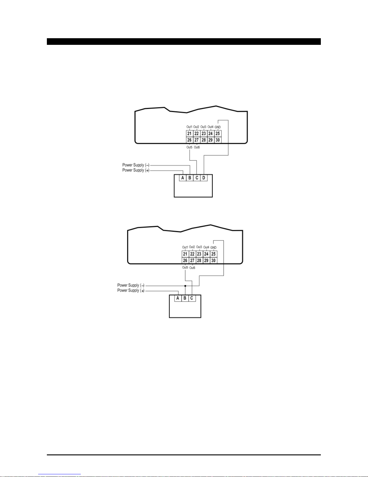
1592025700 IPROFAMILY stp GB 2012.08.08.doc iPro Series 64/72
7.5.4 Devices with 24Vac/dc power supply
3 or 4-row devices that require +24Vac/dc power supply
Each device must be connected through one of the outputs (from Out1 to Out6), whereas the power supply
as shown in the diagram below.
This is an example for versions IPG-IPC.
For all the others version, verify the correct number of the pin in the connector.
Recommendations:
- respect the “+” and “-“ polarities of the power supply.
- the power supply of the device must be separate from that of the programmable controller
- follow the diagram of the device used, for the numbering.
- the configuration is determined by the application.
Page 65

1592025700 IPROFAMILY stp GB 2012.08.08.doc iPro Series 65/72
7.5.5 Analogue output for relays (coil power supply 12Vdc)
IPG-IPC IPG 4 DIN
Recommendations:
- follow the diagram of the device used, for the numbering.
- the configuration is determined by the application.
7.6 CONNECTION OF THE DIGITAL OUTPUTS
Depending on the model, the digital outputs can have different connection specifications.
The relays have been split into groups, each with a separate common.
The same voltage must always be used for the various groups of relays and within each group.
For the electrical specifications, refer to the relative paragraphs of the different models.
Certain models have SSR relays (solid state relay), which are suitable to control devices where numerous
commutations are required, which would not be supported by an electromechanical relay. For the electrical
specifications, refer to the specifications of the model using such relays.
Page 66

1592025700 IPROFAMILY stp GB 2012.08.08.doc iPro Series 66/72
7.7 CANBUS CONNECTION
Recommendations:
- follow the diagram of the device used, for the numbering.
Page 67

1592025700 IPROFAMILY stp GB 2012.08.08.doc iPro Series 67/72
7.8 RS485 SLAVE CONNECTIONS
Recommendations:
- follow the diagram of the device used, for the numbering.
Page 68

1592025700 IPROFAMILY stp GB 2012.08.08.doc iPro Series 68/72
7.9 RS485 MASTER CONNECTION
Recommendations:
- follow the diagram of the device used, for the numbering.
Page 69

1592025700 IPROFAMILY stp GB 2012.08.08.doc iPro Series 69/72
NOTE:
____________________________________________________________________________________
____________________________________________________________________________________
____________________________________________________________________________________
____________________________________________________________________________________
____________________________________________________________________________________
____________________________________________________________________________________
____________________________________________________________________________________
____________________________________________________________________________________
____________________________________________________________________________________
____________________________________________________________________________________
____________________________________________________________________________________
____________________________________________________________________________________
____________________________________________________________________________________
____________________________________________________________________________________
____________________________________________________________________________________
____________________________________________________________________________________
____________________________________________________________________________________
____________________________________________________________________________________
____________________________________________________________________________________
____________________________________________________________________________________
____________________________________________________________________________________
____________________________________________________________________________________
____________________________________________________________________________________
____________________________________________________________________________________
____________________________________________________________________________________
____________________________________________________________________________________
____________________________________________________________________________________
____________________________________________________________________________________
Page 70

1592025700 IPROFAMILY stp GB 2012.08.08.doc iPro Series 70/72
NOTE:
____________________________________________________________________________________
____________________________________________________________________________________
____________________________________________________________________________________
____________________________________________________________________________________
____________________________________________________________________________________
____________________________________________________________________________________
____________________________________________________________________________________
____________________________________________________________________________________
____________________________________________________________________________________
____________________________________________________________________________________
____________________________________________________________________________________
____________________________________________________________________________________
____________________________________________________________________________________
____________________________________________________________________________________
____________________________________________________________________________________
____________________________________________________________________________________
____________________________________________________________________________________
____________________________________________________________________________________
____________________________________________________________________________________
____________________________________________________________________________________
____________________________________________________________________________________
____________________________________________________________________________________
____________________________________________________________________________________
____________________________________________________________________________________
____________________________________________________________________________________
____________________________________________________________________________________
____________________________________________________________________________________
____________________________________________________________________________________
Page 71

1592025700 IPROFAMILY stp GB 2012.08.08.doc iPro Series 71/72
NOTE:
____________________________________________________________________________________
____________________________________________________________________________________
____________________________________________________________________________________
____________________________________________________________________________________
____________________________________________________________________________________
____________________________________________________________________________________
____________________________________________________________________________________
____________________________________________________________________________________
____________________________________________________________________________________
____________________________________________________________________________________
____________________________________________________________________________________
____________________________________________________________________________________
____________________________________________________________________________________
____________________________________________________________________________________
____________________________________________________________________________________
____________________________________________________________________________________
____________________________________________________________________________________
____________________________________________________________________________________
____________________________________________________________________________________
____________________________________________________________________________________
____________________________________________________________________________________
____________________________________________________________________________________
____________________________________________________________________________________
____________________________________________________________________________________
____________________________________________________________________________________
____________________________________________________________________________________
____________________________________________________________________________________
___________________________________________________________________________________
Page 72

1592025700 IPROFAMILY stp GB 2012.08.08.doc iPro Series 72/72
 Loading...