

Page 1
IC100C Series PRELIMINARY
1592015000 Manual IC100C Series 28/05/03 Page 1 di 38
dIXEL
Instruction Manual
Page 2
IC100C Series PRELIMINARY
1592015000 Manual IC100C Series 28/05/03 Page 2 di 38
INDEX
1. General Advices__________________________ 2
2. User Interface____________________________ 3
3. Key Function ____________________________ 3
4. Keyboard Leds___________________________ 4
5. Remote Keyboard VI610 ___________________ 4
6. Normal Condition read-out _________________ 4
7. Silencing the Buzzer ______________________ 5
8. First Installing ___________________________ 5
9. How to Set the Clock RTC__________________ 5
10. “ Hot Key” Programming __________________ 5
11. Keyboard Programming ___________________ 5
12. Change the Password _____________________ 6
13. Value of Display Read–Out Par. CF36 ________ 6
14. Start / Stop Chiller or Heat Pump ____________ 7
15. Stand- By Function _______________________ 7
16. “M key” the Function Menu_________________ 7
17. Keyboard Functions ______________________ 8
18. How to Turn a Compressr in Off-Line ________ 8
19. Dynamic Set Point ________________________ 8
20. Energy Saving ___________________________9
21. Compressor Functioning __________________ 9
22. Condenser Fan Regulation ________________10
23. Hot Start Function _______________________ 11
24. Automatic Change - Over _________________ 11
25. Defrost Function ________________________ 11
26. Relay Configuration______________________ 12
27. Data Logger ____________________________12
28. Boiler Function__________________________ 12
29. Maintenance Function____________________ 12
30. Black Out ______________________________ 12
31. Installing and Mounting___________________ 12
32. Electrical Wiring_________________________ 13
33. Alarm Code and Events___________________ 14
34. Output Lock for Alarm Event Table _________ 17
35. Connecting Diagram _____________________ 18
36. Parameter description____________________ 19
37. Parameter Table_________________________ 27
38. Technical Data __________________________ 38
1. GENERAL ADVICES
• Please read before using this manual
• This manual is part of the product and should be kept near the
instrument for easy and quick reference.
• The instrument shall not be used for purposes different from
those described hereunder. It cannot be used as a safety
device.
• Check the application limits before proceeding.
1.1 Safety Precaution
• Check the supply voltage is correct before connecting the
instrument.
• Do not expose to water or moisture: use the controller only
within the operating limits avoiding sudden temperature
changes with high atmospheric humidity to prevent
formation of condensation
• Warning: disconnect all electrical connections before any
kind of maintenance.
• Fit the probe where it is not accessible by the End User. The
instrument must not be opened.
• In case of failure or faulty operation send the instrument
back to the distributor or to “Dixell s.r.l.” (see address) with a
detailed description of the fault.
• Consider the maximum current which can be applied to each
relay (see Technical Data).
• Ensure that the wires for probes, loads and the power supply
are separated and far enough from each other, without
crossing or intertwining.
• In case of applications in industrial environments, the use of
mains filters (our mod. FT1) in parallel with inductive loads
could be useful.
Page 3
IC100C Series PRELIMINARY
1592015000 Manual IC100C Series 28/05/03 Page 3 di 38
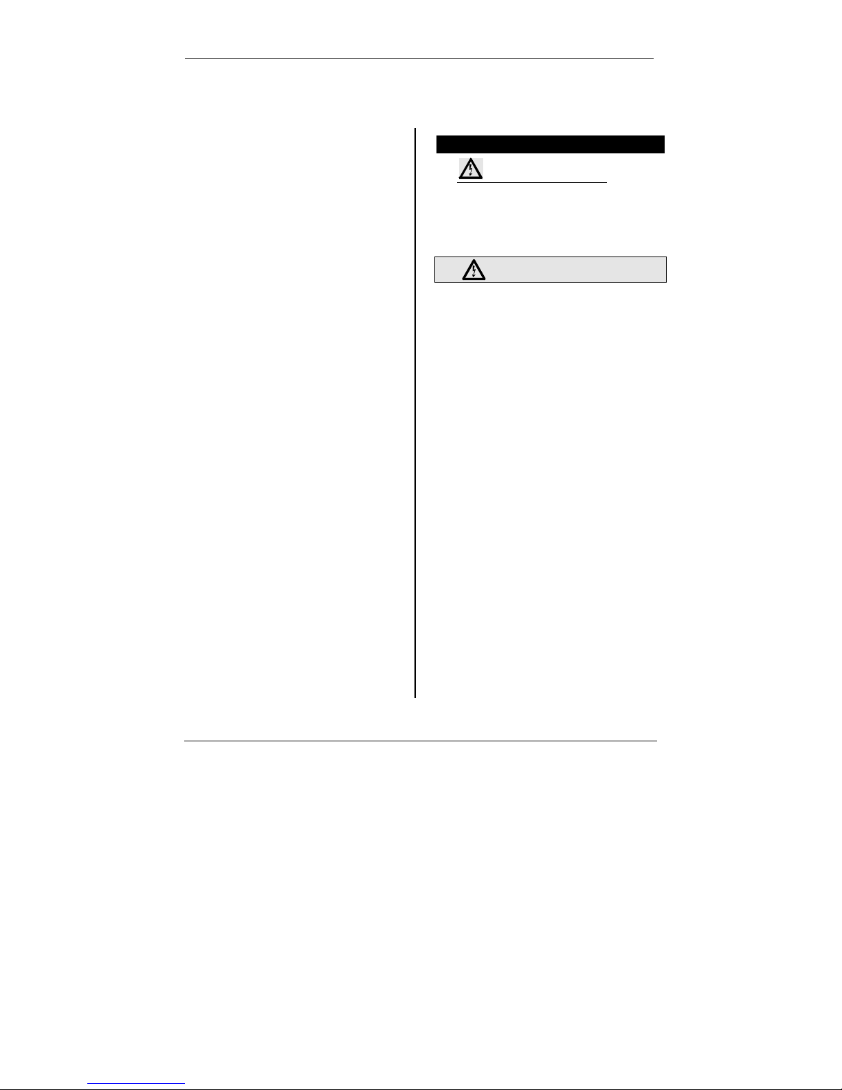
2. USER INTERFACE
2.1 Display
The display area is divided in three parts:
Left Upper Side : It shows the evaporator “water IN /
OUT” temperature or the inlet air of the air/air unit.
Left Lower Side : It shows the temperature or the pressure
of the condenser and the clock time.
Right Side: Icon area.
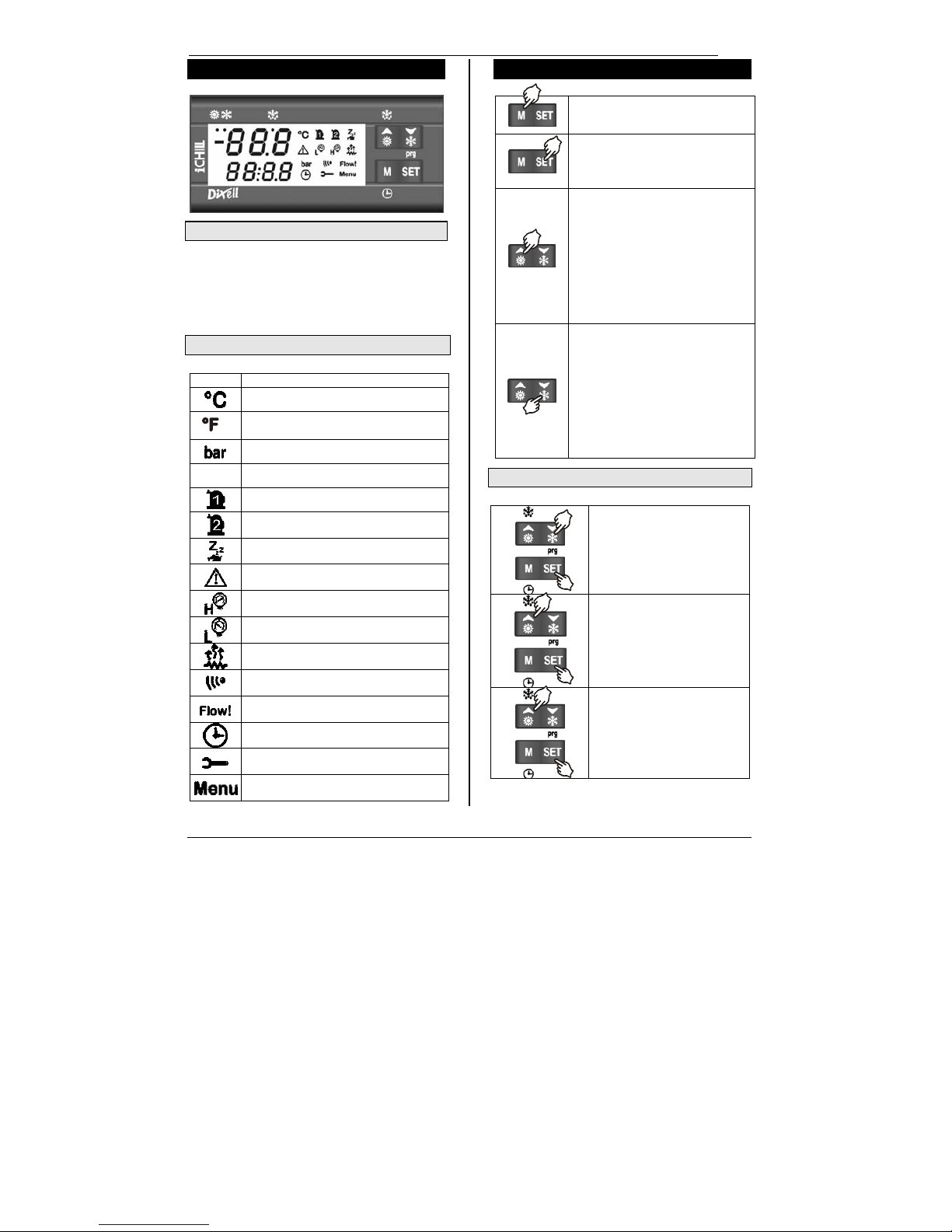
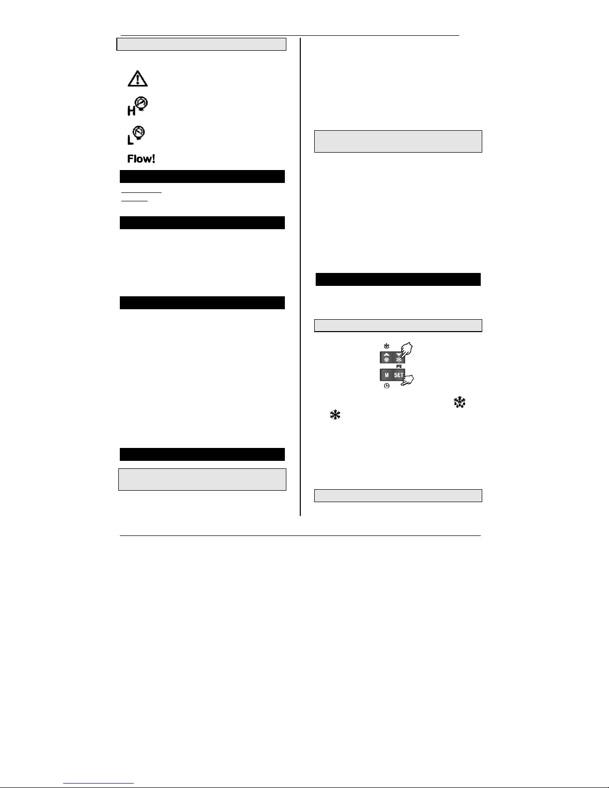
2.2 Icons of the Display
Icon Meaning
Celsius degrees
Fahrenheit degrees
Bar
Psi
Compressor 1
Compressor 2
Unit in Stand-by
General Alarm
High pressure Alarm
Low pressure Alarm
Anti-freeze electric heater activated
Infrared Transmission activated
Water Flow Alarm
The display is showing a time value
Compressor Maintenance Request
Function Menu activated
3. KEY FUNCTION
1. M to enter the function Menu or to
set the clock
1. SET allows to show and modify
the set point.
2. In programming mode it selects a
parameter and confirm its value.
1. Depending on the programming,
push it for 5 s to run the unit in
Chiller or Heat Pump mode.
2. Push and release to change the
read-out between “IN/OUT water”
/ supplied air.
3. In programming mode it scrolls
the parameter list or and
decreases the value of the
parameter itself.
4. Depending on the programming,
push it for 5 s to run the unit in
Chiller or Heat Pump mode.
5. Push and release to change the
read-out between “outside air” /
defrost temp.
6. In programming mode it scrolls
the parameter list or and
decreases the value of the
parameter itself.
3.1 Key Combination
Enter the programming.
Exit the programming.
Push them together for more than
5 sec to start a manual defrost.
PSI
Page 4
IC100C Series PRELIMINARY
1592015000 Manual IC100C Series 28/05/03 Page 4 di 38
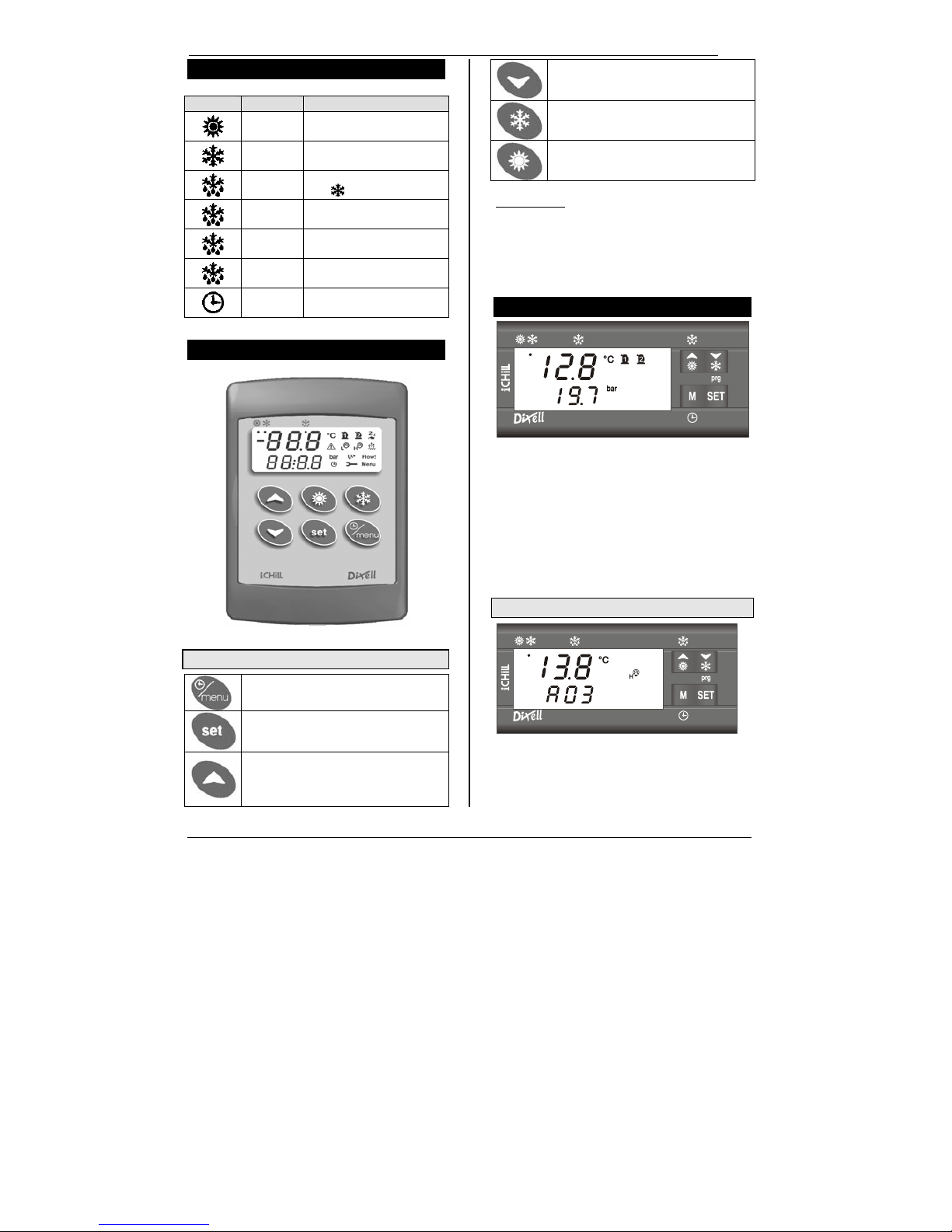
4. KEYBOARD LEDS
Symbol Led Function
On Heat pump
On Chiller
Blinking
Programming phase (It blinks
with
led)
Blinking Time delay before defrosting
On Defrost On
Off Defrost Off
Clock Set-up
5. REMOTE KEYBOARD VI610
5.1 Key Function
M allows to enter the menu or to set the clock
time.
SET allows to show and modify the set point.
During the programming it selects a
parameter and confirm its value.
It selects the water IN / OUT or the ambient
air read-outs. During the programming it
scrolls the parameter code or increases its
value.
It selects the external /defrost air temperature
read-out. During the programming it scrolls
the parameter code or decreases its value.
If pushed for 5s it allows to start the unit in
chiller or heat pump function.
If pushed for 5s it allow to start the unit in
chiller or heat pump function.
For Air/Air unit
: using the remote keyboard with NTC
sensor on board ( VI610S model) and with the parameter
CF35 = 2, the read-out and the regulation are controlled by
the NTC sensor mounted on the remote keyboard. When
the communication between the keyboard and the
instrument is broken, the left upper side of the display will
show ”noL” (no link message).
6. NORMAL CONDITION READ-OUT
If no alarm conditions are present, the display shows:
Left upper side:
• Evaporator water Inlet/Outlet (Air/Water,
Water/Water).
• Ambient / evaporator outlet temperatures (Air/Air).
Left lower side:
• Condensing Temperature / Pressure
• Anti-freeze evaporator water (Water/Water with Heat
P.).
• The clock .
6.1 Alarm Read-Out
Starting from the normal condition (no alarms), when the
instrument detects an alarm event, the left lower side
shows the alarm code alternated with the probe value. The
corresponding icon slighted.
Page 5
IC100C Series PRELIMINARY
1592015000 Manual IC100C Series 28/05/03 Page 5 di 38
6.2 Icon Dedicated to the Alarm Read-Outs
The following four icons are dedicated to a better alarm
understanding:
Generic Alarm
High pressure alarm
Low pressure alarm
Water flow Alarm
7. SILENCING THE BUZZER
Automatically: just after the alarm condition is recovered.
Manually
: push and release one of the four keys; the
buzzer is stopped even if the alarm is still active.
8. FIRST INSTALLING
After giving power supply to the instrument, the left lower
display can show “rtC” alternated with the probe value: it is
necessary to set the clock time.
If the probes are not connected, or they are faulty, the
display shows the corresponding alarm code.
In any case it is possible to proceed with the parameter or
clock setting.
9. HOW TO SET THE CLOCK RTC
1. Push the M key for some seconds and wait until the
“Hour” label appears. Release the M key.
2. Now push SET: the hour value starts blinking.
3. Use the
n and o to change the value. Confirm by
pushing SET; After some seconds the controller will
show the next parameter (Min).
4. Repeat the points 2 and 3 to set the other
parameters:
Min: minutes (0÷60)
UdAy: day of the week (Sun = Sunday, Mon = Monday,
tuE = Tuesday, UEd = Wednesday, tHu = Thursday, Fri
= Friday, SAt = Saturday).
dAy: day of the month(0÷31)
MntH: Month (1÷12)
yEAr: Year (00÷99)
10. “ HOT KEY” PROGRAMMING
10.1 Download from the Hot Key (previously
programmed) to the Instrument Memory
The controller power supply is off:
• Insert The Hot Key.
• Turn the power supply on.
• The download starts and lasts some seconds.
During this phase the whole regulation is locked and the
“dOL” message is blinking.
When finishing the “End “ message will appear if the
programming result is good, after 15s the regulation
automatically restarts
If “Err” message appears the operation has given bad
result. Turn the controller off and then on again to repeat
the operation or restart the normal regulation.
10.2 Upload the Parameter from the Controller to
the Hot Key
The instrument is on:
1. Insert the Hot Key.
2. Enter the function menu.
3. Select the UPL function with the arrow keys.
4. Push SET key. The Upload starts immediately from
the instrument to the key memory.
During this phase the whole regulation is locked and the
“UPL” message is blinking.
When finishing the “End “ message will appear if the
programming result is good, after 15s the regulation
automatically restarts
If “Err” message appears the operation has given bad
result. Repeat the points 1-4 for a new Upload.
11. KEYBOARD PROGRAMMING
To allow an easier identification of parameter meaning, the
parameters of the controller have been collected in different
families each one named with a peculiar label.
11.1 “Pr1” Programming Level (User Level)
To enter the “Pr1” User Level:
1) Push the SET +
n key for some seconds ( and
Leeds start blinking) the upper display shows
“ALL” that is the first family of parameters.
2) Using
o and n arrows scroll the other family labels.
3) After finding the right one, push SET key to enter and
see all the parameter belonging to that family, the
display shows the first parameter label and its value.
Scroll the parameter list with
o and n arrows or modify the
value as described in 11.4.
11.2 “Pr2” Parameter Level (Factory Level)
The “Pr2” parameter level is accessible through password:
Page 6

IC100C Series PRELIMINARY
1592015000 Manual IC100C Series 28/05/03 Page 6 di 38
1. Reach “Pr1” as described in 11.1.
2. Select the parameter “Pr2”, the “PAS” label appears
on the upper side.
3. Push SET: the lower display shows Pas while the
upper display 0 blinking.
4. Set the password using
o and n keys.
5. Push SET key to confirm the value.
11.3 How to Move a Parameter from “Pr2” Level
to “Pr1” Level.
Enter the “Pr2” level and select the parameter to move;
keeping pressed the SET key push and immediately
release the n key. One of the nearest led will light to
indicate the presence of the parameter in “Pr1”. Then
release also SET key.
To move the parameter in “Pr2” again: keep pressed SET
key and immediately release the n key. The led turns off so
as the parameter is not more visible in “Pr1” but just in
“Pr2”.
11.4 To Change a Parameter Value
1. Access to programming mode Pr1 or Pr2
2. Select the parameter to change.
3. Push SET key to enable its value.
4. Modify the value with
o and n keys.
5. Push SET key again to confirm the new value, after
some seconds next parameter will be displayed.
6. Exit the programming: push SET +
o, when a
parameter label is displayed, or wait 15s (time-out)
without pushing any keys.
NOTE: The new parameter value is also confirmed if, after
changing it, no SET key is pressed for the time-out to exit.
12. CHANGE THE PASSWORD
Before modifying the password you must know the previous
value. This operation is possible only under Pr2.
1) Enter Pr1 level.
2) Select the family containing the interested
parameters.
3) Push SET key.
4) Using arrows key select the parameter “Pr2”, then
push SET key. The lower display shows “PAS” while
the upper side is 0 blinking.
5) Use
n and o to set the active PASSWORD. push
SET key to reach the Pr2 level.
6) To modify the password: select the “Pr2” parameter.
7) Push SET key to enter the new value (blinking).
8) Insert the new password with
o and n keys.
9) Push SET key to confirm it.
10) The upper display will blink for few seconds then,
next parameter will be showed.
11) Exit the programming by pushing SET + o together
or wait the time-out.
13. VALUE OF DISPLAY READ–OUT PAR. CF36
The parameter data can change depending on CF03
parameter value.
13.1 Parameter CF36 = 0
Upper display shows as default Pb1 probe.
Lower display: if CF06 =1,2,4, it shows Pb3 probe, if
CF07=1,4 it shows Pb4 probe.
13.2 Parameter CF36 = 1
Upper display shows as default Pb2 probe.
Lower display: if CF06 =1,2,4, it shows Pb3 probe,
if CF07=1,4, it shows Pb4 probe.
13.3 Parameter CF36 = 2
Upper display shows as default Pb1 probe.
Lower display shows the clock time.
13.4 Parameter CF36 = 3
Upper display shows Pb2 probe.
Lower display shows the clock time.
If the default probe is Pb1 value, each time the o key is
pressed the upper display shows Pb2 value for 30 seconds
with OUT label. When the time is expired, it comes back to
default Pb1 read-out.
If the default probe is Pb2 value, each time the o key is
pressed the upper display shows Pb1 value for 30 seconds
with IN label. Then it comes back to default Pb1 read-out.
13.5 Display Read-Out when Remote ON/OFF
The digital input configured as remote OFF: if activated it
turns off the controller (also for motocondesing), upper
display shows “OFF ” the decimal point led is blinking.
1. This remote on/off command overrides the
instrument keyboard commands.
2. The keyboard commands are active only when the
digital input is not active.
3. When the remote off is not activated the controller
automatically restarts.
13.6 Upper Display Read-Out with Par. CF02=1
(Motocondensing Unit)
Upper display shows:
“ON” with digital input active
“OFF” with digital input not active.
If the chiller function is selected it turns to OnC.
If the Heat Pump is selected it turns to OnH.
Even for the Motocondensing function the user is allowed
to check the probe values using key arrows and to verify
and manage the alarm events.
Page 7
IC100C Series PRELIMINARY
1592015000 Manual IC100C Series 28/05/03 Page 7 di 38
14. START / STOP CHILLER OR HEAT PUMP
By pressing
key for 5 seconds the unit starts or
stops the Chiller cycle if the parameter CF31 =0, otherwise
if parameter CF31 =1, it starts / stops in Heat Pump mode.
The
led blinks for 5 seconds then it turns on.
To change from Chiller to HP or vice versa, it is necessary
to stop the cycle and then restart the new.
By pressing
key for 5seconds, the unit starts or
stops the Heat Pump cycle if parameter CF31 =0,
otherwise, if parameter CF31 =1, it starts / stops in Chiller
mode.
The
led blinks for 5 seconds then it turns on.
To change from Chiller to HP or vice-versa, it is necessary
to stop the cycle and then restart the new.
15. STAND- BY FUNCTION
Each time the Chiller or Heat Pump cycles are stopped, the
unit goes in stand-by and the
icon turns on.
The controller stand-by allows to:
• Show the probe values using key arrows.
• Show and manage the alarm events.
16. “M KEY” THE FUNCTION MENU
Entering the function Menu allows to:
1. Show and reset the active alarms.
2. Show and reset the time running hour counters of the
loads.
3. Enable the infra-red communication device.
4. Show the time delay to achieve and start the defrost
(only for Heat Pump).
5. Upload the parameters from the controller to the Hot
Key (see 10.2).
6. Show the alarm log.
7. Reset the alarm log.
During the Menu operations the “menu” icon is on.
16.1 Access to Function Menu
Push and release the M key. The ” menu” icon is on.
16.2 Exit from function Menu
Push and release the M key or wait the time out. The
“menu” icon disappears.
16.3 How to Show the Alarm Events
Enter the function Menu:
1. Use
o or n keys to find the “ALrM” label.
2. Push and release the SET key.
3. Use
o or n keys to scroll the alarm list.
To exit the function Menu push and release the M key or
wait the time-out. The “menu” icon disappears.
16.4 How to Reset an Alarm Event
1) Enter the function Menu.
2) Use
o or n keys to find the “ALrM” label.
3) Push and release the SET key, the lower display
shows the alarm code.
4) Upper display: rSt label if the alarm can be reset,
NO label if it is not possible.
Use
o or n keys to scroll the alarm list.
5) Push SET key, when rSt is lighted, to reset the
alarm, after a while the read-out move to next alarm.
6) To exit the function menu push and release the M
key or wait the time-out. The “menu” icon disappears.
16.5 Time Running Hour Counter of the Loads
Enter the function Menu.
Use
o or n keys to find on the lower display:
• C1Hr (Compressor n°1 hour counter),
• C2Hr (Compressor n°2 hour counter),
• PFHr (Water pump or supply fan hour counter).
The upper display shows the time running hour value.
The clock icon
is lighted.
16.6 Reset the Hour Counters
1. Enter the function Menu.
2. Use
o or n keys to find on the lower display the
C1Hr, C2Hr or PFHr.
3. Push SET key for 3seconds: the upper display turns
to 0 indicating the reset.
4. To exit the function menu push and release the M
key or wait the time-out. The “menu” icon disappears.
16.7 Show the Time Delay to Start the Defrost
1. Enter the function Menu.
2. Use o or n keys to find, on the upper display, the
dEF (defrost) label, the lower display shows the time
delay to reach and start the defrost (minutes and
seconds), the icon
is blinking.
3. To exit the function menu push and release the M
key or wait the time-out. The “menu” icon disappears.
16.8 Infrared Transmission Procedure
1. Enter the function Menu.
2. Use o or n keys to find, on the lower display, the “Ir”
label while, the upper display shows label ALr =
ALARM ;
Par = PARAMETER;
LOG = RECORDED DATA.
3. Push and release SET key.
Page 8

IC100C Series PRELIMINARY
1592015000 Manual IC100C Series 28/05/03 Page 8 di 38
4. If the password is active enter its value.
5. The infrared icon
is now lighted. The controller
starts sending the data. You have 1 minute to place
the IR receiver device in front of the instrument.
6. On the receiver, push RX key to enable the
receiving: the RX led blinks during the interlacing
procedure. During the data transferring the RX is
lighted, it turns off to signal the end of the procedure.
7. To exit the function menu push and release the M
key or wait the time-out. The “menu” icon disappears.
16.9 How to See the Alarm Log
1. Enter the function Menu.
2. Use o or n keys to find ALOG label.
3. Push SET key: the lower display shows the alarm
code, the upper display shows “n°” followed by the
progressive number.
4. With o or n scroll the alarm list.
5. To exit from ALOG function push M key or wait the
time-out delay is expired.
The memory contains 50 alarm events structured in a FIFO
list. Each new alarm will take the place of the oldest alarm
contained in the FIFO list. ( the read-out is ordered from the
oldest to the newest)
16.10 How to Reset the Alarm Log
1) Enter the function Menu.
2) Select the ALOG label showed on the lower display.
3) Push SET key.
4) Select with o or n keys the ArSt (Alarm reset) label
on the lower display, the upper display is PAS.
5) Push SET key and then enter the password PAS,
upper display shows 0 blinking.
6) Write the right password number.
7) The ArSt label starts blinking for 5s, to confirm the
alarm logging data is reset.
After finishing the display restarts from normal condition.
17. KEYBOARD FUNCTIONS
17.1 How to See the Set Point Value
Push and release the SET key.
Lower display shows: SetC set of chiller mode;
SetH set of heat pump mode.
The upper display shows the corresponding set value.
(SetH is available only if configured for Heat Pump).
17.2 How to Change the Set Point Value
1) Push SET key for more than 3 seconds.
2) The setpoint value is now blinking.
3) Use o and n
to increase or decrease the new value.
When finishing, push and release SET key again or wait for
the time-out to exit the programming.
17.3 How to See the Set Point with Energy
Saving or Dynamic Set Functions Enabled
When working in Chiller or Heat Pump, the first time SET
key is pushed the lower display shows SEtC (set chiller); or
SEtH (set heat pump) and the upper shows its value.
When the “Energy Saving” is activated, by pressing SET
key again, the lower display shows “SEtS” (set saving)
while the upper display will turn to the real setpoint value
used to control the unit during this function.
When working with “Dynamic Set”, by pushing SET again,
the lower display shows “SEtd” (set dynamic), while the
upper display will turn to the real setpoint value used to
control the unit during this function.
The SEtS or SETd appears only if the corresponding
functions are activated.
18. HOW TO TURN A COMPRESSR IN OFF-LINE
A compressor can be turned off for maintenance or if it is in
bad condition, without interfering with the normal cycle of
the unit. Therefore, it is not necessary to stop the unit or the
cycle.
1. Access the programming mode.
2. Find and then set the parameter CO12 = 1
(compressor 1 = OFF: out of the process control).
3. If necessary find and then set also the parameter
CO13 = 1 (2
nd
comp. / step 1stcomp.= OFF).
To restore the compressor in the process control set the
C012 and/or C013 parameter = 0.
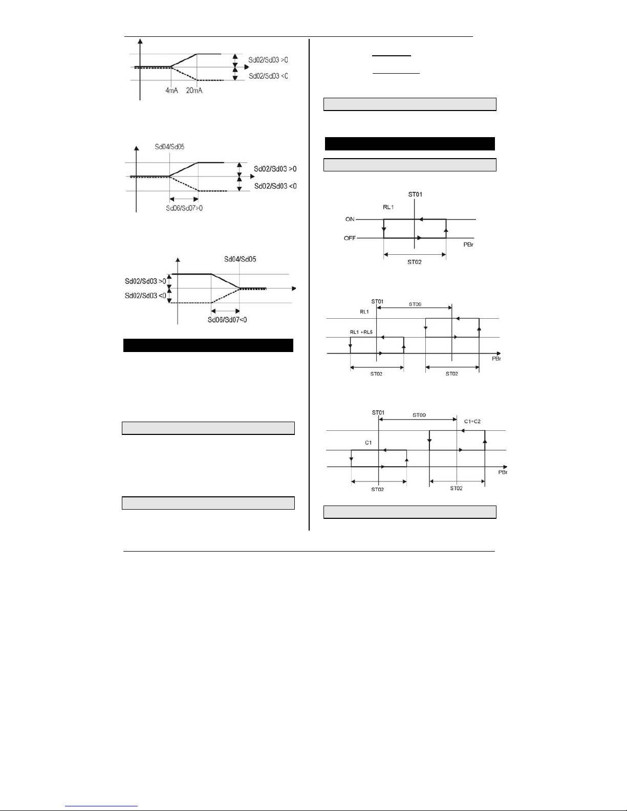
19. DYNAMIC SET POINT
This function is useful to save energy or to run the unit with
particular external air temperature condition. It allows to
increase or reduce the setpoint with a positive or negative
proportional offset. This value is combined with parameters
Sd02 (for Chiller) or Sd03 (for HP), the 4...20mA analogue
input or the outside air temperature.
The Dynamic Set is enabled if:
- The parameters Sd01 = 1 and CF06 = 3, Pb3 probe
configured as 4..20mA signal;
- The parameter Sd01 = 1 and CF07 = 3, Pb4 probe
configured as outside air temperature. If the parameter
CF07=3, by pushing and releasing the n key the upper
display shows for 30 seconds the outside air temperature
while the lower display shows Et (external temperature)
label.
Pb3 probe configured as 4..20mA input signal (below)
Page 9
IC100C Series PRELIMINARY
1592015000 Manual IC100C Series 28/05/03 Page 9 di 38
Pb4 probe with positive differential (below)
Pb4 probe with negative differential (below)
20. ENERGY SAVING
It is daily or weekly configurable function with “hour time
table” (if RTC on board) or depending from external digital
input. During the Energy Saving cycle the real setpoint is
calculated with the parameters ES10 and ES12:
SET+ES10 for chiller, SET+ES12 for Heat Pump.
The differential for the function cut-in/out is depending by
ES11 for Chiller and ES13 for Heat Pump.
20.1 Daily Programming
The daily programming is based on 7 parameters ES03>ES09 corresponding to the 7 days of the week; the value
1 enable the function for that day.
Eg: ES03 = 1 means that the Energy Saving is activated for
the whole 24 hours on Monday. If needed, repeat the
operation for the whole week ES04(Tue)..ES09(Sun).
20.2 Hour Time Table (with RTC)
Based on two parameters: ES01 Energy Saving start hour
and ES02 Energy Saving stop hour.
Eg: ES01 = 8.0 and ES02 = 10.0 it means that the Energy
Saving is active from 8 to 10.0
for all the days of the week.
Eg: ES01 = 23.0 and ES02 = 8.0 it means that the Energy
Saving is active from 23.0 to 8.0
of the next morning; for all
the days of the week. This function is disabled if the
parameters ES01 / ES02 are both 0.
20.3 Energy Saving with External Contact
The function is enabled when the digital input, configured
as Energy Saving, is activated by remote contact.
21. COMPRESSOR FUNCTIONING
21.1 Compressor Control in Chiller Mode
Parameter CF21=0,3 (1 Compressor selected)
Parameter CF21=1 (1 compressor with step)
Parameter CF21=2 ( 2 compressor )
21.2 Compressor Regulation for Heat Pump
Parameter CF21=0,3 (1 compressor)
Page 10
IC100C Series PRELIMINARY
1592015000 Manual IC100C Series 28/05/03 Page 10 di 38
Parameter CF21=1 (1 compressor with step)
Parameter CF21=2 (2 compressors)
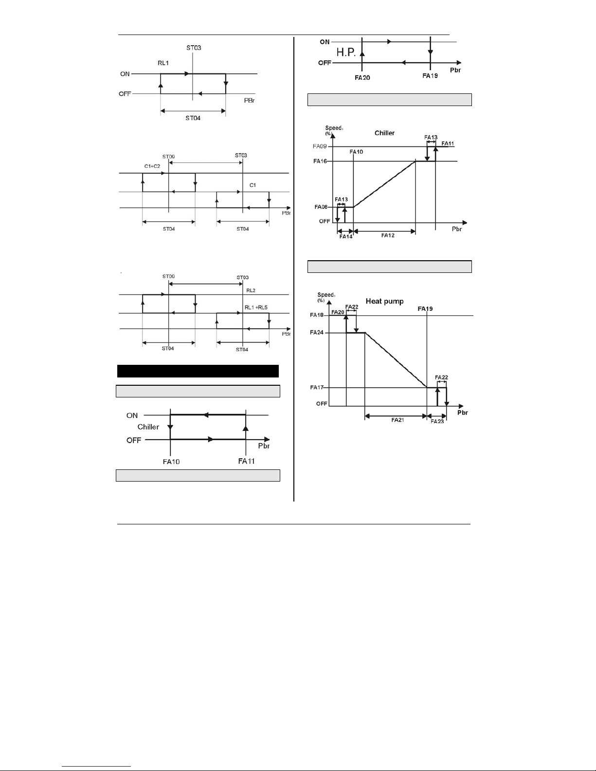
22. CONDENSER FAN REGULATION
22.1 ON/OFF Fan in Chiller Mode
22.2 ON/OFF Fan in Heat Pump
22.3 Triac or 4..20mA Output in Chiller Mode
22.4 Triac or 4..20mA Output in Heat Pump
Page 11
IC100C Series PRELIMINARY
1592015000 Manual IC100C Series 28/05/03 Page 11 di 38
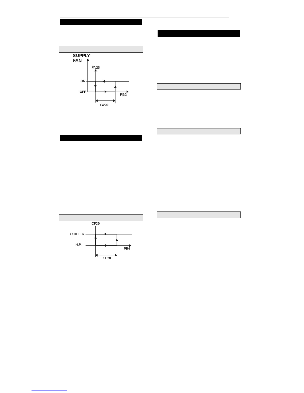
23. HOT START FUNCTION
Available only if the parameter CF01=1 air/air unit
configured as heat pump, it allows to start the supply air fan
only if the temperature of the condenser side is enough hot.
This avoid to push cold air flow into the ambient.
23.1 Hot Start Fan Graphic Function
FA25 Set point of the Hot Start
Set the temperature value, detected by the Pb2 probe,
under which the fan is keep locked.
FA26 Differential of the Hot Start
Set the differential to regulate the fan ON/OFF.
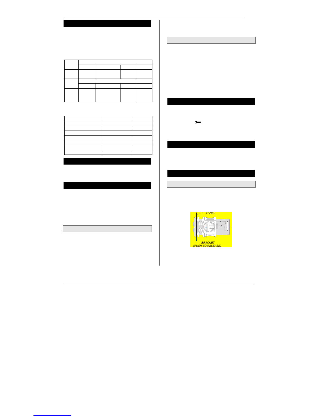
24. AUTOMATIC CHANGE - OVER
It automatic changes the chiller <-> heat pump functioning
of the unit in correlation with the external temperature
condition.
The changing occurs only when the following condition are
satisfied, otherwise the unit turns to stand-by:
1. CF01=1,3,5,7 (Heat Pump selected).
2. CF28=2 and CF07=3 (Pb4 external air temperature).
3. Pb4 probe is not faulty.
The Change Over function is regulated by parameters:
CF29 is the set point and it represents the Pb4 value under
which the controller turns to Heat Pump mode.
CF30 represents the temperature differential to turns to
Chiller mode.
The user can find helpful information by pushing and
releasing
n key so as the upper display shows the Pb4
value while the lower display shows Et label.
24.1 Graph Regulation of the Change-Over
When the temperature value is within the CF30 range, the
changeover is allowed only though keyboard.
25. DEFROST FUNCTION
The defrost cycle is enabled only if the following condition
are satisfied:
1. CF01=1,3,7 configuration chiller unit with heat pump.
2. dF01=1 defrost cycle enabled.
3. CF20=0 relay n°4 configured as reversing valve.
4. The unit is working in heat pump mode.
5. Pb3 or Pb4 must be configured as control
condensing probe without active faulty probe alarms.
If only one of these conditions is not satisfied the defrost
does not operate.
25.1 Forced Defrost
This function is enabled only if dF05 <> 0 and allows to
operate a defrost even during the counting of the time delay
dF10 and if the temperature/pressure value lower than the
parameter dF19 value for the dF05 time value.
If during the time delay dF05 the temperature/pressure
becomes higher than the parameters dF1+dF20
(differential) value then the whole procedure is stopped and
the time delay dF05 will be reloaded.
25.2 Combined Defrost
This function is enabled only if CF07 = 5 and with Pb4
configured as NTC probe therefore it is used for external
temperature on the evaporator coil during the heat pump
mode. The detected temperature allows to calculate a
better defrost cycle giving the start and the end commands
for the cycle itself. Functioning:
The Pb3 probe gives the input signal, to start the time delay
counting, when its value is lower than dF03 parameter.
After the delay dF10 the controller check Pb4 value: if lower
than dF11 the defrost procedure starts otherwise the unit
still works in Heat Pump. Just after the temperature
decreases under dF11 the defrost is enabled. The
combined defrost stops just when Pb4 probe value reaches
the end defrost temperature in dF12. If the combined
defrost is enabled is possible through key, to see the
external temperature showed on the upper display for 30
seconds while the lower display shows dEF label.
25.3 Manual Defrost
The unit is working with 1 or 2 compressor running.
The start defrost temperature/pressure value must be lower
than dF03.
If the “combined defrost” is enabled, Pb4 value must be
lower than dF11.
If the above conditions are satisfied, by pushing SET + o
for more than 5s the defrost cycle immediately starts.
Page 12
IC100C Series PRELIMINARY
1592015000 Manual IC100C Series 28/05/03 Page 12 di 38
26. RELAY CONFIGURATION
Relay n° 1 = Compressor 1
Relay n° 2-3 automatically change their configuration
depending on the unit configuration.
Relay n° 2 = Anti-freeze heater CF01 = 2-3-4-5; integration
heater with CF01 = 0 - 1
Relay n° 3 = Water pump, with CF01 = 2-3-4-5; supply air
fan CF01 = 0 –1
Value of par.CF20
Relay
0 1
°n 4
Inversing
valve
Fan ON/OFF
Value of par.CF21
Relay
0 1 2 3
°n 5 Alarm
Stage of the 1
st
compressor.
2
nd
compre
ssor
Fan
ON/OFF
When working with one compressor with one stage valve:
the relay n°5 is configured as stage valve CF21=1: the
polarity of the stage valve is determined by C010.
CO10 = 0 RL1 comp. RL5 parz.
No call OFF OFF
Compressor call ON OFF
1st Stage call ON ON
CO10 = 1 RL1 comp. RL5 parz.
No call OFF ON
Compressor call ON ON
1st Stage call ON OFF
27. DATA LOGGER
The data recording is enabled if the log time LG08 > 0.
The recordable data can be included enabling the LG01 to
LG07 parameters.
28. BOILER FUNCTION
The electric heater can be activated as heating integration
control Ar20=0 or heating control Ar20=1 during the heat
pump functioning mode.
It is enabled only if:
• Unit configured in Heat Pump mode CF01=3-5.
• Pb4 configured as external air probe CF07=3.
28.1 Heating Integration Control Ar20=0
The Boiler function starts when the Pb4 probe value
decreases under Ar21 value.
If the water temperature detected by the regulation probe is
lower than the ST03 parameter, the electric resistance
heater is activated. The on/off algorithm of the electric
resistance heater is the same as the compressor control
with Heat Pump mode.
If the external air temperature becomes higher than Ar21 +
Ar22 (differential), the integration function stops working
and the unit restarts (or still work) with Heat Pump mode.
28.2 Heating Control Ar20=1
The Boiler function begins when the Pb4 probe decreases
under Ar21 value. When the delay is expired, if the water
temperature detected by the regulation probe is lower than
the ST03 parameter, the compressors are stopped while
the electric resistance heater is activated. The on/off
algorithm of the electric resistance heater is the same as
the compressor control with Heat Pump mode.
If the external air temperature becomes higher than Ar21 +
Ar22 (differential), the Boiler functions stops working and
the unit restarts with Heat Pump mode, compressors and
fans restart working.
29. MAINTENANCE FUNCTION
CO14 for 1st compressor, CO15 for 2nd compressor and
CO16 for water pump or supplied air fan (air/air) are the
maximum time running hours to signal a maintenance
request, the icon
is blinking. The icon only indicates
the need of a check: nothing else happens. It stops
blinking just after resetting the hour counter under the
function Menu.
30. BLACK OUT
After a black-out:
1. The controller restarts from the pervious status.
2. The defrost cycle is stopped.
3. All the working time delay will be reloaded.
31. INSTALLING AND MOUNTING
31.1 “C” Format (32*74mm)
The instrument shall be mounted on panel, in a 29x71 mm
hole, and fixed using the special bracket supplied.
To obtain an IP65 protection grade use the front panel
rubber gasket (mod. RG-C) as shown in figure 1.
Page 13

IC100C Series PRELIMINARY
1592015000 Manual IC100C Series 28/05/03 Page 13 di 38
Fig. 1
31.2 “V” Format
Remote terminal “Vertical” shape
Mounted on a panel with 72x56 mm cut-out, fixed with
screw.
To obtain the IP65 protection, even for the panel, use the
rubber gasket RGW-V (optional). For wall mounting use the
V-KIT plastic adapter as illustrated in figure 2.
Fig. 2
The temperature range allowed for correct operation is -10÷60°C. Avoid places subject to strong vibrations,
corrosive gases, excessive dirt or humidity. The same
recommendations apply to probes. Let air circulate by the
cooling holes.
32. ELECTRICAL WIRING
The controller is provided with removable terminal blocks
for wires having section not bigger than 1.0 mm
2
:
14 ways for analogue and digital inputs,
12 ways for relays
Note: terminals 17-19 are connected inside the controller,
they are the common for the “relay n°1” with terminal 15
and “relay n°2” with terminal 16
Terminals 21-22 are connected inside the controller, they
are the common for the “relay n°3 ” with terminal 18 and
“relay n°4” with terminal 20.
A 5-ways connector is dedicated to the TTL / RS485
interface.
Four connectors having 2-way for 0.2 mm
2
wires are
dedicated to: remote terminal, 12Vdc open collector alarm,
Pb4 probe, 4..20mA analogue output.
Remote terminal is provided with 2-ways screw terminal
block for wires not bigger than 2.5 mm
2
. Check power
supply data before connection wires. Keep the probe
and the digital input wires separate from the power
cable. Do not exceed the maximum rating current for each
relay, check technical data and if the load is bigger, use
filtered contactors.
Page 14

IC100C Series PRELIMINARY
1592015000 Manual IC100C Series 28/05/03 Page 14 di 38
33. ALARM CODE AND EVENTS
Cod Meaning Cause / Origin Instrument behaviour Reset
P1 Pb1 probe alarm Missing, faulty
probe or resistance
exceeding value
Open collector / alarm relay ON
Buzzer ON
General alarm icon lighted
Alarm code on display
Automatic if the probe value
recovers
P2 Pb2 probe alarm Missing, faulty
probe or resistance
exceeding value
Open collector / alarm relay ON
Buzzer ON
General alarm icon lighted
Alarm code on display
Automatic if the probe value
recover
P3 Pb3 probe alarm Missing, faulty
probe or resistance
/current exceeding
value
Open collector / alarm relay ON
Buzzer ON
General alarm icon lighted
Alarm code on display
Automatic if the probe value
recovers
P4 Pb4 probe alarm Missing, faulty
probe or resistance
exceeding value
Open collector / alarm relay ON
Buzzer ON
General alarm icon lighted
Alarm code on display
Automatic if the probe value
recovers
A01 High pressure
switch alarm
Digital input for
high pressure
activated
Open collector / alarm relay ON
Buzzer ON
High pressure icon lighted
Alarm code on display
Manual:
after the alarm event expires,
proceed with manual reset.
A02 Low pressure
switch alarm
Digital input for low
pressure activated
Open collector / alarm relay ON
Buzzer ON
Low pressure icon lighted
Alarm code on display
Automatic.
It turns to manual after AL02
events in 1 hour.
Manual:
after the alarm event expires,
proceed with manual reset.
A03 Low temperature
alarm of the
supplied
temperature
Digital input active
if CF01=0,1 and
Pb1< AR03 for
AR05 seconds.
Open collector / alarm relay ON
Buzzer ON
General alarm icon lighted
Alarm code on display
Automatic:
when Pb1 value increases over
AR03+AR04 value.
A04 Low temperature
alarm of the outlet
air from
evaporator.
Digital input active
if CF01=0,1 and
Pb2< AR03 for
AR05 seconds
Open collector / alarm relay ON
Buzzer ON
General alarm icon lighted
Alarm code on display
Automatic.
It turns to manual after Ar06
events in 1 hour.
Manual:
the event expires if Pb2 >
(AR03+ AR04), then proceed
with manual reset.
A05 High temperature
High pressure
Digital input active
Pb3 o Pb4 > AL11
Open collector / alarm relay ON
Buzzer ON
High alarm icon lighted
Alarm code on display
Manual:
the event expires if Pb3 or Pb4
< (AL11-AL12), then proceed
with manual reset.
A06 Low temperature
Low pressure
Digital input active
Pb3 o Pb4 < AL14
Open collector / alarm relay ON
Buzzer ON
Low alarm icon lighted
Alarm code on display
Automatic.
It turns to manual after AL06
events in 1 hour.
Manual:
the event expires if Pb3 or Pb4
> (AL14+AL15), then proceed
with manual reset.
Page 15

IC100C Series PRELIMINARY
1592015000 Manual IC100C Series 28/05/03 Page 15 di 38
A07 Anti freeze alarm Digital input active
anti freeze probe
Pbr < AR03 for
minimum AR05
seconds
Open collector / alarm relay ON
Buzzer ON
General alarm icon lighted
Alarm code on display
Automatic.
It turns to manual after Ar06
events in 1 hour.
Manual:
the event expires if Pbr >
(AR03+AR04), then proceed
with manual reset.
A07 Anti freeze alarm
motocondensing
unit
Digital input active
CF01=6,7 and
CF05=2
Open collector / alarm relay ON
Buzzer ON
General alarm icon lighted
Alarm code on display
Automatic.
It turns to manual Ar06 events
in 1 hour.
Manual:
the event expires, then proceed
with manual reset.
A08 Water flow alarm
(air/water
water/water;
Supply air fan
thermal protection
(air/air)
Digital input active
for AL06 duration.
Open collector / alarm relay ON
Buzzer ON
Flow alarm icon lighted
Alarm code on display
Automatic.
It turns to manual after Ar05
events in 1 hour.
Manual:
the event expires for AL07,
then proceed with manual
reset.
A09 Compressor 1
thermal protection
alarm
Digital input active Open collector / alarm relay ON
Buzzer ON
General alarm icon lighted
Alarm code on display
Manual:
the event expires, then proceed
with manual reset.
After AL09 events in 1 hour
and digital input not active, set
AL10=0 to resume.
A10 Compressor 2
thermal protection
alarm
Digital input active Open collector / alarm relay ON
Buzzer ON
General alarm icon lighted
Alarm code on display
Manual:
the event expires, then proceed
with manual reset. After AL09
events in 1 hour and digital
input not active, set AL10=0 to
resume.
A11 Condenser fan
thermal protection
alarm
Digital input active Open collector / alarm relay ON
Buzzer ON
General alarm icon lighted
Alarm code on display
Manual:
the event expires, then proceed
with manual reset.
A12 Defrost error alarm End defrost after
dF07 (Max defrost
length) with
dF02=2
Only alarm code on display Automatic:
with next proper defrost cycle.
Proceed with manual reset.
A13 Compressor 1
maintenance
warning
Running hour >
CO14
Open collector / alarm relay ON
Buzzer ON
Maintenance icon lighted
Alarm code on display
Manual:
Proceed with the hour reset
procedure 16.6
A14 Compressor 2
maintenance
warning
Running hour >
CO15
Open collector / alarm relay ON
Buzzer ON
Maintenance icon lighted
Alarm code on display
Manual:
Proceed with the hour reset
procedure 16.6
Page 16

IC100C Series PRELIMINARY
1592015000 Manual IC100C Series 28/05/03 Page 16 di 38
A15 Water pump or
supply air fan
(air/air) maint.
Warning
Running hour >
CO16
Open collector / alarm relay ON
Buzzer ON
Maintenance icon lighted
Alarm code on display
Manual:
Proceed with the hour reset
procedure 16.6
rtC Clock alarm Need to set the
clock time
Open collector / alarm relay ON
Buzzer ON
General alarm icon lighted
Alarm code on display
Manual:
Set the clock and then proceed
with manual reset.
rtF Clock alarm Faulty clock control Open collector / alarm relay ON
Buzzer ON
General alarm icon lighted
Alarm code on display
Manual:
Proceed with manual reset, if
nothing happens change the
clock.
EE EEPROM error
alarm
Possible data
losing
Open collector / alarm relay ON
Buzzer ON
General alarm icon lighted
Alarm code on display
Manual:
Proceed with manual reset., if
nothing happens the controller
is locked, no regulation
available.
ACF1 Configuration
alarm
Heat pump
configured without
reversing valve
Open collector / alarm relay ON
Buzzer ON
General alarm icon lighted
Alarm code on display
Automatic
After parameter proper debug.
ACF2 Configuration
alarm
CF01= 0-1-2-3 and
FA02 =1-2, without
condensing probe
control
configuration
Open collector / alarm relay ON
Buzzer ON
General alarm icon lighted
Alarm code on display
Automatic
After parameter proper debug.
ACF3 Configuration
alarm
Two digital inputs
having the same
function
Open collector / alarm relay ON
Buzzer ON
General alarm icon lighted
Alarm code on display
Automatic
After parameter proper debug.
ACF4 Configuration
alarm
CF28= 1 & digital
input not
configured or
CF28= 2 probe
Pb4 <> 3
Open collector / alarm relay ON
Buzzer ON
General alarm icon lighted
Alarm code on display
Automatic
After parameter proper debug.
ACF5 Configuration
alarm
CF02 =1 & (CF04
≠2,3 & CF05 ≠ 3 )
or ( CF04 = 2 and
CF05 = 3 )
Open collector / alarm relay ON
Buzzer ON
General alarm icon lighted
Alarm code on display
Automatic
After parameter proper debug.
FErr Functioning alarm CF04=3 and
CF05=3 With
digital input
activated at the
same time
Open collector / alarm relay ON
Buzzer ON
General alarm icon lighted
Alarm code on display
Manual:
after the alarm event expires,
proceed with manual reset.
AFr Frequency alarm The frequency of
power supply is out
of range
Open collector / alarm relay ON
Buzzer ON
General alarm icon lighted
Alarm code on display
Automatic
After the frequency becomes
normal
Page 17

IC100C Series PRELIMINARY
1592015000 Manual IC100C Series 28/05/03 Page 17 di 38
34. OUTPUT LOCK FOR ALARM EVENT TABLE
Alarm
Code
Alarm Description Comp. 1 Comp. 2 Anti - freeze
Heater
Water
Pump
Supply
air fan
Cond.
fan
P1 Pb1 Probe Alarm Yes Yes
Yes
with Ar19 =0
Yes
P2 Pb2 Probe Alarm Yes Yes
Yes
with Ar19 =0
Yes
P3 Pb3 Probe Alarm Yes Yes
Yes
with Ar19 =0
Yes
P4 Pb4 Probe Alarm Yes Yes
Yes
with Ar19 =0
Yes
A01 High pressure alarm from digital input Yes Yes
A02 Low pressure alarm from digital input Yes Yes Yes
A03 Low temperature alarm of supplied air
A04 Low temperature outlet air Yes Yes Yes Yes
A05 High temperature / high pressure alarm Yes Yes
A06 Low temperature / low pressure alarm Yes Yes Yes
A07 Anti freezer digital input Yes Yes Yes
A07 Anti-freeze digital input alarm Yes Yes Yes
A07 Anti-freeze alarm motocondensing unit Yes Yes Yes Yes
A08 Water flow Alarm Yes Yes
Heater - boiler
Yes
Yes
A08 Supply air fan thermal protection CF01= 0,1 Yes Yes
Integration
heater Yes
Yes
A09 Compressor 1 thermal protection Yes
A10 Compressor 2 thermal protection Yes
A11 Condenser fan thermal protection Yes Yes Yes
A12 Defrost error
A13 Compressor 1 maintenance
A14 Compressor 2 maintenance
A15 Water pump / supply air fan maintenance
rtC Clock alarm
rtF Clock alarm
EE Eeprom error Yes Yes Yes Yes Yes Yes
ACF1 Configuration alarm Yes Yes Yes Yes Yes Yes
ACF2 Configuration alarm Yes Yes Yes Yes Yes Yes
ACF3 Configuration alarm Yes Yes Yes Yes Yes Yes
ACF4 Configuration alarm Yes Yes Yes Yes Yes Yes
ACF5 Configuration alarm Yes Yes Yes Yes Yes Yes
FErr Functioning error (motocond. ) Yes Yes Yes Yes Yes
AFr Frequency alarm Yes Yes Yes Yes Yes Yes
Page 18

IC100C Series PRELIMINARY
1592015000 Manual IC100C Series 28/05/03 Page 18 di 38
35. CONNECTING DIAGRAM
“
”
*
=
Page 19

IC100C Series PRELIMINARY
1592015000 Manual IC100C Series 28/05/03 Page 19 di 38
36. PARAMETER DESCRIPTION
36.1 Regulation Parameters
ST01 Setpoint in Chiller mode(range ST05..ST06).
ST02 Differential of the Chiller mode.
ST03 Setpoint in Heat Pump mode (range
ST07..ST08)
ST04 Differential of the Heat Pump mode.
ST05 Minimum limit value of ST01 settable for Chiller
mode (range -40°C / °F…ST01).
ST06 Maximum limit value of ST01 settable for Chiller
mode (range ST01…110 °C / 230°F).
ST07 Minimum limit value of ST03 settable for Heat
Pump mode ( range –40°C / °F...ST03).
ST08 Maximum limit value of ST03 settable for Heat
Pump mode (range ST03…110 °C / 230°F).
ST09 Regulation band
36.2 Configuration parameters
CF01 configure the type of the unit. Based on this
parameter some parameters can be hidden. (see the
table - menu)
Type of unit:
0= Chiller air / air
1= Chiller air / air with heat pump
2= Chiller air / water
3= Chiller air / water with heat pump
4= Chiller water / water
5= Chiller water / water with heat pump
CF02 Motocondensing Unit
0= Yes; 1= No
CF03 Regulation probe
0= Pb1 probe control; 1= Pb2 probe control
CF04 Pb1 analogue input configuration:
0 = No Probe
1 = NTC probe for evaporator water inlet / controlled
air showed on the upper display.
2 = Digital input for Motocondensing unit.
When the contact is not active the unit turns to standby, upper display shows OFF.
The active input turns the unit in stand-by but the
upper display shows ON.
In this situation using o and n keys is possible to start
the functioning in Chiller or Heat Pump mode:
in Chiller mode
the upper display shows OnC. If
CF21=2 and CO08=1 the 1
st
compressor starts, with
CF21=2 and CO08=0 the compressor with less
counted hours starts.
in Heat Pump mode
the upper display shows OnH.:
with CF21=2 and CO08=1 the 1
st
compressor starts,
with CF21=2 and CO08=0 the compressor with less
counted hours starts.
If the digital input becomes not active and then active
again the unit stops and then restarts with the
selected mode. Only with active input is possible to
change the functioning again through o and n keys.
3 = Digital input for motocondensing unit. It turns the
unit on only in Chiller mode, the upper display shows
OnC. If the contact is not active the unit turns to
stand-by and the display shows OFF. Only with active
contact, if the unit has been turned off through o and
n keys, is possible to turn it on again through o and n
keys.
CF05 Pb2 input configuration
0 = no Probe
1 = NTC probe temperature “evaporator water outlet”/
“evaporator out air”, it is showed on the upper display.
2 = Digital input to generate the anti-freeze alarm,
check the polarity.
3 = Digital input for motocondensing. If active it starts
the unit in Heat Pump, the upper display shows OnH.
While, if not active, the unit is in stand-by, the upper
display shows OFF. Only if this input is active is
possible to turn Off and On the unit through o and n
keys.
CF06 Pb3 input configuration
0 = no Probe
1 = NTC temperature probe to control the condenser
fan speed, it is showed on the lower display.
2 = 4..20mA condensing pressure input to control the
condenser fan speed, it is showed on the lower
display.
3 = 4..20mA Dynamic Setpoint input signal decided by
the user.
4 = NTC condenser probe anti-freeze alarm
(water/water or water/water with Heat Pump) , it is
showed on the lower display.
CF07 Pb4 input configuration
0 = no Probe
1 = NTC temperature probe to control the condenser
fan speed, it is showed on the lower display.
2 = Configurable digital input.
3 = NTC probe for outdoor air control. It works for:
Dynamic Setpoint, Boiler and Auto Change–over.
4 = NTC probe for condenser anti-freeze alarm
(water/ water or water/water with Heat Pump), It is
showed on the lower display.
5= NTC probe to detect the evaporator temperature in
Heat Pump and control the Combined Defrost. It
determines the defrost start and stop.
6= NTC probe used only for the data logger function.
CF08 Digital input configuration ID1
CF09 Digital input configuration ID2
CF10 Digital input configuration ID5
Page 20

IC100C Series PRELIMINARY
1592015000 Manual IC100C Series 28/05/03 Page 20 di 38
CF11 determines the functions of Pb4 when
configured as digital input:
0= If active it generates a compressor 1 thermal
protection alarm.
1= If active it generates a condenser fan thermal
protection alarm.
2= If active it generates a supply air fan (air/air) /
water flow (water/air, water/water) thermal protection
alarm.
3= If active it generates a remote OFF command. The
instrument keyboard works only if the input is not
active.
4= Remote “Chiller / Heat Pump” command. The
instrument keyboard can start the unit only with the
operating mode selected by remote. (See CF28 = 1) .
5= If active it generates a 2
nd
compressor thermal
protection alarm.
6= External call for 2
nd
compressor / stage
(Motocondensing).
7 = If active it determines the end defrost cycle.
8 = If active it enables the Energy Saving function.
9 = If active it generates an “Anti ice alarm”.
ID3 = If active it generates the high pressure alarm.
ID4 = If active it generates the high pressure alarm.
CF12 Digital input polarity ID1
CF13 Digital input polarity ID2
CF14 Digital input polarity ID3
CF15 Digital input polarity ID4
CF16 Digital input polarity ID5
CF17 Input polarity of Pb1 when set as digital input.
CF18 Input polarity of Pb2 when set as digital input.
CF19 Input polarity of Pb4 when set as digital input.
0 = Input active for closed contact.
1 = Input active for open contact.
CF20 Configuration of the relay n°4.
0 = Inversing valve;
1 = Condenser fan.
The output polarity of the relay n°4 if CF20 = 0 is
defined by the parameter dF18.
CF21 Configuration of the relay n°5.
0 = Alarm relay;
1 = One Compressor with 1 stage;
2 = Two Compressors;
3 = Condenser fan.
Note rele’ n°5 output polarity.
If CF21 = 0 the output polarity is defined by par. AL18.
If CF21 = 1 the stage valve polarity is defined by par.
CO10.
CF22 Corresponding pressure value at 4mA of Pb3.
CF23 Corresponding pressure value at 20mA of Pb3.
CF24 Offset of Pb1 probe to calibrate the read-out.
CF25 Offset of Pb2 probe to calibrate the read-out.
CF26 Offset of Pb3 probe to calibrate the read-out.
CF27 Offset of Pb4 probe to calibrate the read-out.
CF28 It determines which command has the priority to
turn the unit in Chiller or Heat Pump.
CF28 = 0 Keyboard commands override the digital
input commands ( see cap 12).
CF28 = 1 Digital input with priority control commands.
It is enabled only when one of the digital inputs is
configured to change the function “Chiller / Heat
Pump“ of the unit.
If the polarity of that digital input is 0:
- Open contact means Chiller functioning
- Closed contact means Heat Pump functioning.
If the polarity of that digital input is 0:
- Open contact means Heat Pump functioning
- Closed contact means Chiller functioning.
If none of the digital inputs is set to 4, the unit turns
to stand-by. The keyboard selection is disabled and
the unit can run only with the selected mode.
CF28 = 2 Analogue input commands override
instrument keyboard commands. If the temperature is
within the CF30 interval, the changing of status is
allowed also from instrument keyboard.
If CF28=1, CF28=2 and the unit is running, a request
of change the functioning will turn off all the relay
outputs. Then the controller will wait few time,
signalled by the Chiller or Heat Pump blinking led,
before restarting with the compressor delay times of
the new functioning.
CF29 Change Over Setpoint.
If the functioning is selected with probe control, it
represents the temperature under which Pb4 probe
value automatically turns the unit to Heat Pump mode.
CF30 Change Over differential.
If the functioning is selected with probe control, it
represents the temperature differential for Pb4 probe
value to turns the unit to Chiller mode.
CF31 Chiller and Heat Pump keys configuration.
0 = Pushing
key for 5s, it turns on / off the unit in
Chiller mode, pushing
key for 5s, it turns on / off in
Heat Pump mode.
1 = Pushing
key for 5s, it turns on / off the unit in
Heat Pump mode, pushing
key for 5s, it turns on /
off the unit in Chiller mode.
CF32 Selects the unit of measurement.
0 = Celsius °C / bar
1 = Fahrenheit / psi
CF33 Selects the power supply frequency.
0 = 50 Hz
1 = 60Hz
CF34 Serial Address for monitoring system.
CF35 Number of remote keyboards push buttons.
0 = 4 push buttons
1 = 6 push buttons
2 = 6 push buttons with NTC sensor
Page 21

IC100C Series PRELIMINARY
1592015000 Manual IC100C Series 28/05/03 Page 21 di 38
CF36 Default read-out of the display.
0 = Pb1 on the upper side, Pb3 or Pb4 on the lower
side.
1 = Pb2 on the upper side, Pb3 or Pb4 on the lower
side.
2 = Pb1 on the upper side, the clock on the lower
side.
3 = Pb2 on the upper side, the clock on the lower
side.
CF37 Firmware release identification.
CF38 Eeprom parameter map identification.
Pr2 Password value from 0 to 999.
36.3 Dynamic Setpoint Parameters
Sd01 Dynamic Setpoint configuration.
0 = Function enabled;
1 = Function disabled.
Sd02 It determines the maximum offset of the setpoint
value reachable in Chiller mode.
Sd03 It determines the maximum offset of the setpoint
value reachable in Heat Pump mode.
Sd04 External air temperature setpoint in Chiller
mode.
Sd05 External air temperature setpoint in H.P. mode.
Sd06 External air temperature differential in Chiller
mode.
Sd07 External air temperature differential in Heat
Pump mode.
36.4 Energy Saving Parameters
ES01 Energy Saving start time
ES02 Energy Saving stop time
ES03 Monday….ES09 Sunday
0 = Not enabled; 1 = Enabled
ES10 Energy Saving increment in Chiller mode.
ES11 Energy Saving differential in Chiller mode.
ES12 Energy Saving increment in Heat Pump mode.
ES13 Energy Saving differential in Heat Pump mode.
36.5 Compressor Parameters
CO01 Minimum ON time after compressor activation.
CO02 Minimum OFF time after compressor de-
activation. During this time the corresponding icon is
blinking.
CO03 Delay time between compressor or stage
activation to reduce current peak consumption. During
this time the corresponding icon is blinking.
When working with a compressor with stage, if there
is a full load request, the stage solenoid is activated
and only after 5 seconds the compressor. After the
delay time CO03 if not needed the stage solenoid is
turned off.
CO04 Off delay time between compressor or stage
valve.
CO05 Delay time at power supply start-up.
All the output relays are delayed for the time set in
this parameter to prevent compressor damages from
frequent power supply black-outs.
CO06 Compressor switch on delay time after “water
pump / air supply fan” relay activation.
Having CO11 = 2 (“water pump / air supply fan”
related to compressor on/off status), the “water pump
/ air supply fan” always starts before the compressors.
Having CO11 = 1 (continuously running of pump/fan)
the relay switches on when the controller is turned on
in Chiller or Heat Pump mode. No delay time are
enabled.
Page 22

IC100C Series PRELIMINARY
1592015000 Manual IC100C Series 28/05/03 Page 22 di 38
CO07 “Water pump / air supply fan” switch off delay
time after compressor deactivating.
Having CO11 = 2 (“water pump / air supply fan”
related to compressor on/off status), the “water pump
/ air supply fan” always stops after the compressors.
Having CO11 = 1 (continuously running of pump/fan)
the relay switches off when the controller turns to
stand-by mode.
CO08 Compressor control sequences.
0 = Compressor rotating sequence.
Depending on the number of running hours the
controller enables the compressor with less counted
running hours. The switch off sequence stops the
compressor with greater number of running hours.
Rotating sequence is not enabled for units having a
compressor with a stage.
1 = Fixed sequence control.
Compressor_1 always starts before Compressor_2
and stops always after Compressor_2 stops.
In case of compressor_1 alarm the compressor_2
immediately stops.
CO09 Reserved.
CO10 Stage polarity valve.
0 = stage active for valve ON (relay closed);
1 = stage active for valve OFF (relay open).
CO11 “Water pump / air supply fan” relay
configuration.
0 = Relay not configured..
1 = Continuously running. The relay switches on when
the controller is turned to Chiller or Heat Pump mode.
2 = “water pump / air supply fan” is related to
compressor on/off status (par CO06 , CO07
activated).
CO12 Compressor_1 off line for maintenance.
0 = ON; 1 = OFF
If set to OFF, the compressor is not more included
into the regulation and the relay output will never be
turned on. To include the compressor this parameter
must be set to 0.
CO13 2
nd
compressor or stage off line for
maintenance.
0 = ON; 1 = OFF
If set to OFF, the compressor is not more included
into the regulation and the relay output will never be
turned on. To include the compressor this parameter
must be set to 0.
CO14 Alarm setpoint for compressor n°1 running
hour.
Number of compressor running hour before signalling
the warning alarm A13. If 0 the function is not
enabled.
CO15 Alarm setpoint for compressor n°2 running
hour. Number of compressor running hour before
signalling the warning alarm A14. If 0 the function is
not enabled.
CO16 Alarm setpoint for pump/fan running hour.
Number of pump/fan running hour before signalling
the warning alarm A15. If 0 the function is not
enabled.
36.6 Ventilation parameters
FA01 It enables the condenser fan output.
0 = Not enabled;
1 = Enabled.
FA02 It selects, with parameter FA03, the type of
condenser fan regulation.
0 = (with FA03=0) fan ON with compressor ON.
0 = (with FA03=1) fan ON but independent from
compressor and Off in stand –by.
1 = (with FA03=0) fan ON with compressor ON
following the ON/OFF regulation of the condensing
temperature/pressure trend.
When compressor goes OFF also fan goes OFF.
1 = (with FA03=1) fan ON/OFF following the
condensing temperature/pressure trend.
2 = (with FA03=0) fan ON when compressor ON with
proportional regulation (triac and 4..20mA outputs)
based on condensing pressure/temperature trend.
When compressor goes OFF also fan regulation goes
OFF.
2 = (with FA03=1) fan ON/OFF with proportional
regulation (triac and 4..20mA outputs) based on
condensing pressure/temperature trend.
FA03 Condensing fan and compressor status.
Page 23

IC100C Series PRELIMINARY
1592015000 Manual IC100C Series 28/05/03 Page 23 di 38
0 = Fan related to the compressor status;
1 = Fan independent from compressor.
FA04 Maximum fan speed time after starting request.
If FA02=2 and the condenser fan control is the triac
output, when starting the regulation the trigger output
will drive the condenser fan at the maximum voltage
for the time FA04 then, the regulation will follow the
temperature/pressure of the probe.
If FA04 = 0 this function is not enabled.
FA05 Phase shifting of the fan motor.
Used to compensate the different fan motor. It is
expressed in micro seconds.
FA06 Not used.
FA07 Maximum fan speed time, in Chiller mode,
before switching on the compressor. Used to
compensate the condenser pressure rising value to
get a better regulation.
If FA07 = 0 this function is not enabled.
FA08 Minimum speed for condenser fan in Chiller
mode.
FA09 Maximum speed for condenser fan in Chiller
mode.
FA10 Temperature/pressure value that corresponds
to the minimum condenser fan speed FA08 in Chiller.
FA11 Temperature/pressure value that corresponds
to the maximum condenser fan speed FA09 in Chiller.
FA12 Proportional band for condenser fan control in
Chiller mode.
It allows to set the band within the controller increases
or decreases the fan speed. (default value is the
difference between FA10 and FA11)
FA13 Temperature/pressure differential to stop the
condenser fan in Chiller mode.
FA14 Temperature/pressure differential to keep the
minimum speed in Chiller mode.
FA15 Time delay before activating the CUT–OFF
function after a compressor starting.
If after a compressor starting, the proportional
regulation requires to stop the fan (cut-off) and
FA15≠0, the condenser fan runs at minimum speed
for this time. If FA15=0 the function is not enabled.
FA16 Night function (limited speed) in Chiller
It allows to set a limited speed in Chiller to prevent
noises. To enable it the value must be lower than
FA11.
FA17 Minimum fan speed in Heat Pump Mode.
FA18 Maximum fan speed in Heat Pump Mode.
FA19 Temperature/pressure value that corresponds
to the minimum condenser fan speed in Heat Pump.
FA20 Temperature/pressure value that corresponds
to the Maximum condenser fan speed in Heat Pump.
FA21 Proportional band for condenser fan control in
Heat Pump mode.
It allows to set the band within the controller increases
or decreases the fan speed. (default value is the
difference between Fa19 and Fa20).
FA22 Temperature/pressure differential to stop the
condenser fan in Heat Pump mode.
FA23 Temperature/pressure differential to keep the
regulation with the minimum speed in Heat Pump
mode.
FA24 Night function (limited speed) in Heat Pump
It allows to set a limited speed in Heat Pump to
prevent noises.
FA25 Hot Start Setpoint.
Temperature value detected by Pb2 under which the
supply air fan is stopped.
Only for air/air configuration and heat pump mode.
It starts the fan only if the condenser temperature is
hot enough avoiding cold air flows.
FA26 Hot start differential.
36.7 Anti-freeze, Boiler, integration heater
parameters
Ar01 Anti-freeze: minimum limit for setpoint Ar03 (–40
°C…Ar03)
Ar02 Anti-freeze: maximum limit for setpoint Ar03
(Ar03…110 °C)
Ar03 Anti-freeze Setpoint (range Ar0 …Ar02).
Under this value the controller shows an anti-freeze
alarm:
Pb1 ambient air low temperature for air/air unit,
Pb2 low outlet temperature for air/air unit.
Ar04 Anti-freeze alarm differential. It determines the
alarm reset if temperature is rising.
Ar05 Anti-freeze alarm delay time. It determines the
minimum time, with temperature always lower than
Ar03, before signalling the anti-freeze alarm.
Ar06 Maximum anti-freeze alarm number before
turning to manual reset procedure. After this number
of anti-freeze alarms the controller obliges to execute
a manual alarm reset.
Ar07 Anti-freeze alarm delay time of the outlet air
when starting in Heat Pump mode.
It determines a delay time before signalling the alarm
because the Heat Pump mode will heat the water or
the air. If after this time the temperature is still lower
than Ar03 the unit is immediately turned off.
Ar08 «Anti-freeze heater / integration heater»
Setpoint (air/air unit) in Chiller mode.
Temperature value under which the controller
switches on the anti-freeze heater (with probe NTC
Pb1-Pb2).
Ar09 «Anti-freeze heater / integration heater»
Setpoint for air/air unit in Heat Pump mode.
Page 24

IC100C Series PRELIMINARY
1592015000 Manual IC100C Series 28/05/03 Page 24 di 38
Temperature value under which the controller
switches on the anti-freeze heater (with probe NTC
Pb1-Pb2).
Ar10 Setpoint anti-freeze heater for water/water unit
in Heat Pump mode.
Temperature value under which the controller
switches on the anti-freeze heater (with probe NTC
Pb3-Pb4).
Ar11 «Anti-freeze heater / integration heater»
differential in Chiller mode.
Ar12 «Anti-freeze heater / integration heater»
differential in Heat Pump mode.
Ar13 «Anti-freeze heater / integration heater»
configuration.
0 = ON with instrument control.
1 = ON with instrument control and active defrost
cycle (always on during defrost)
Ar14 «anti-freeze heater / integration heater» set-up
in Chiller.
0 = OFF in Chiller
1 = ON in chiller (on when necessary).
Ar15 anti-freeze heater /integration heater setup in
Heat Pump.
0 = OFF in Heat Pump;
1 = ON in Heat Pump (on when necessary)
Ar16 Probe selection for «anti-freeze heater /
integration heater» in Chiller mode:
0 = Pb1 probe control;
1 = Pb2 probe control.
Ar17 Probe selection for «anti-freeze heater /
integration heater» in Heat Pump mode:
0 = Pb1 probe control;
1 = Pb2 probe control.
Ar18 Anti-freeze heater in Stand-by status. It
determines the status of the “anti-freeze heater
/integration heater” when the controller functioning is
off or stand-by:
0 = Always OFF;
1 = Running on controller demand.
Ar19 Anti-freeze heater safety for faulty probe.
0 = Always off for faulty probe.
1 = Always on for faulty probe.
Boiler Function Parameters
Ar20 The Boiler function allows to control the
electrical heater in Heat Pump mode:
0 = Integration control; 1 = Heating control.
Ar21 External air Setpoint for electrical heater control.
Ar22 Boiler temperature differential.
36.8 Defrost Parameters
dF01 Defrost cycle control.
0 = No; 1 = Yes
dF02 Type of defrost cycle.
0 = Temperature/pressure control. The defrost delay
counting time dF10 starts just after the
temperature/pressure goes below the setpoint dF03.
The defrost stops for temperature/pressure control.
1 = Maximum time length defrost. The defrost delay
counting time dF10 begins just after the
temperature/pressure goes below the setpoint dF03.
The defrost stops after the time set in dF07.
2 = External contact defrost. The defrost delay
counting time dF10 begins just after the
temperature/pressure goes below the setpoint dF03.
The defrost starts if the external contact is not active
but stops when the contact becomes active.
dF03 Temperature/pressure value under which the
defrost delay dF10 starts counting.
dF04 End defrost temperature/pressure setpoint.
When the temperature rising over this value the
defrost stops.
dF05 Time delay before starting a forced defrost. The
function is enabled if dF05<>0. It starts a defrost cycle
(even if dF10 time is not expired), if the
temperature/pressure is lower than the set dF19 for
the time dF05 duration. If during dF05 the
temperature/pressure rises over the set dF19 + dF20
(differential) the defrost cycle is postponed and the
delay time dF05 is reloaded.
dF06 Minimum defrost duration. It determines the
minimum time duration of a defrost cycle even if the
other end defrost conditions have been already
satisfied.
dF07 Maximum defrost duration. It determines the
end of the defrost if dF02 = 1. In other cases it
determines the maximum time.
dF08 Pause time before starting the defrost ( the
compressor led is blinking). After the dF10 delay,
before turning on the defrost cycle, the controller
stops the compressor for the time set in dF08. To
allows the pressure balancing, exactly in the middle of
the dF08 counting (dF08/2), the 4-way reversing valve
is activated. The delay times of the compressor are
not calculated. If dF08=0 the compressor does not
stops and the 4-way valve is immediately activated.
dF09 Pause time after defrost (the compressor led is
blinking). To allows the pressure balancing and the
water draining the Heat Pump functioning restarts
only after the time set in dF09 parameter. In the
middle of dF09 counting the 4-ways valve is
deactivated. The compressor delay times are not
calculated.
If dF09 = 0 the compressor does not stop and the
valve is immediately activated.
dF10 Interval time between defrosts. The counting
starts when the condenser temperature/pressure
detected (Pb3/Pb4) is lower than DF03.In case of
Page 25

IC100C Series PRELIMINARY
1592015000 Manual IC100C Series 28/05/03 Page 25 di 38
supply black-out or changed functioning mode the
defrost is postponed and the dF10 is reloaded. The
counting stops if the compressor stops or if the
temperature/pressure becomes higher than DF03.
dF11 Start Defrost Setpoint. It is enabled when (Pb4
CF07=5) and (Pb3 CF06=1 o 2 ).
The counting begins when the temperature/pressure
of Pb3 probe becomes lower than dF03. When the
dF10 delay time is expired the controller check the
Pb4, if lower than dF11 the defrost starts otherwise
the unit will continue in Heat Pump. Just after Pb4
becomes lower than dF11 the defrost starts.
dF12 End of combined defrost temperature.
It permits to set the temperature over which the
combined defrost stops working.
The analogue input Pb4 configured in CF07 =5
enables the combined end defrost control. The defrost
cycle stops when Pb4 reaches this setpoint.
dF13 2
nd
Compressor ON during the defrost cycle.
0 = OFF; 1 = 2
nd
Compressor ON
If the unit is configured with 2 compressors CF21=2
and dF13=1, both the compressors are ON in defrost.
The delay times are not calculated therefore ON and
OFF compressor is instantaneous.
dF14 Condenser Fan ON during defrost and draining
cycles (dF09).
0 = Not Enabled;
1 = Enabled only in defrost cycle;
2 = Enabled in defrost and draining cycles.
If dF14=1 and the condensing temperature/pressure
increases over dF15 value, the fan control will be
driven with the Chiller configuration fan parameter.
If dF14=2 after the defrost, for the time set in dF09
the fan will be forced to maximum speed.
dF15 Temperature/pressure setpoint to force the fan.
dF16 Low alarm detection during defrost.
0 = not enabled; 1 = enabled.
dF17 Low alarm delay time in Heat Pump mode.
With dF08 and dF09 set to 0 (compressor does not
stop and 4-ways valve immediately active), the
pressure of the circuit is not well balanced for valve
changing. In this case the dF17 delay starts counting
each time the valve changes its status to avoid
stopping the unit for low alarm.
dF18 4-ways inverting valve polarity.
0 = Active in chiller; 1 = Active in Heat Pump.
dF19 Temperature/pressure Setpoint to force the
defrost cycle.
dF20 Differential for forced defrost.
36.9 Alarm Parameters
AL01 Low pressure alarm delay time.
It determines the time delay before signalling the low
pressure alarm from digital input.
AL02 Maximum number of “low pressure alarm” /
hour before turning to manual reset procedure
AL03 Low alarm detection with unit in Off or Stand-by.
0 = Alarm not enabled; 1 = Alarm enabled.
AL04 Water flow alarm delay time. After starting the
water pump the alarm is suppressed for this time.
AL05 Maximum number of “ Water flow alarm” in one
hour.
If the number of flow alarm events reaches the value
set in this parameter in one hour, the alarm turns to
manual reset procedure. The water pump is turned
off.
ATTENTION with CF01=2, 3, 4, 5 the minimum value
is 1 event.
AL06 Minimum activation time for water flow alarm.
The alarm is detected only if the condition persists for
the time set in this parameter. The counting starts
only after the AL04 is expired. It prevents from
possible alarms due to the presence of air into the
water pipe.
Water flow alarm note: the open collector and relay
alarm outputs works only for alarm conditions during
the functioning. In the other cases the alarm is only
displayed with blinking icon. With Boiler function the
active alarm stops the pump. The evaporator is
automatically protected with the anti-ice control.
CO11=0 Water pump not present.
The alarm is managed only if one of the digital inputs
is configured as water flow, the alarm reset is
automatic.
CO11=1 “Water pump on” continuously.
The alarm is managed only if one of the digital inputs
is configured as water flow, the alarm reset is
automatic with Stand–by or remote Off (pump off).
The pump is running until reaches AL05 alarm events
if working in Chiller or Heat Pump mode. In this case
the loads will be deactivated as described in table and
the reset turns to manual procedure.
CO11=2 “Water pump on” in parallel with compressor.
The alarm is managed only if one of the digital inputs
is configured as water flow, the alarm reset is
automatic with Stand–by or remote Off (pump off). It
turns to manual reset procedure after reaching AL05
alarm events in Chiller or Heat Pump mode. The
loads are deactivated as described in table 34. The
water pump follow the cycle with CO06 On delay time
and CO07 Off delay time; after AL05 alarm events is
stopped.
Water flow alarm manual reset procedure.
After AL05 alarm events it is necessary to enter the
function Menu to reset it. The flow icon is lighted and
does not disappear if the alarm is still active. The
water pump, if managed, can start and the alarm is
Page 26

IC100C Series PRELIMINARY
1592015000 Manual IC100C Series 28/05/03 Page 26 di 38
by-passed for AL04 (to control the unit restart) if
during this time the alarm recovers.
AL07 Minimum time with inactive water flow input
(after alarm event).
After a water flow alarm event, with stop compressor,
the regulation restarts only if after this time the digital
input is not more active. It prevents from a possible
series of short alarms due to the presence of air into
the water pipe.
AL08 Thermal protection alarm delay time for
compressors.
After switching on the compressor the thermal
protection alarm is not detected for the time set in this
parameter.
AL09 Number of maximum thermal protection alarm
events.
If during one hour the number of thermal alarms
reaches the value set in this parameter, the alarm
reset turns to manual procedure.
AL10 Thermal protection alarm reset after AL09
events/hour.
After the number of maximum alarms/hour for
compressors 1–2, AL10 parameter automatically
change to 1. To reset this alarm is necessary to enter
the programming and change it again to 0.
This operation executed only by personnel in charge
for the maintenance prevent compressor damaging
caused by frequently alarm resets.
AL11 Condensing high temperature/pressure alarm
setpoint. When the condenser probe value increases
over this value the instrument detects this high alarm.
AL12 Condensing temperature/pressure differential to
reset the high alarm.
AL13 Condensing low temperature/pressure alarm
delay time for analogue input. After a compressor
starting, the low pressure alarm coming from digital
input is delayed for the time set in this parameter.
AL14 Condensing low temperature/pressure alarm
setpoint. When the condenser probe value decreases
under this value the instrument detects this low alarm.
AL15 Condensing temperature/pressure differential to
reset the low alarm.
AL16 Maximum number of low pressure alarms in
one hour before turning to manual reset procedure.
AL17 Open collector and relay alarm output control
when the unit is in Off or in Stand-by status.
0 = Outputs not enabled for alarm events;
1 = Outputs enabled for alarm events.
AL18 Alarm output polarity.
0 = Active for closed contact (open for normal condit.);
1 = Active for open contact (closed for normal condit.)
AL19 Alarm printout language through IR device.
36.10 Logging Parameters
The data recording is enabled only for IR device
mounted on board and the parameter LG08<>0. The
parameters from LG01 to LG07 can enable which are
the recordable data .
LG01 Functioning status (Chiller, Heat Pump,
Standby)
0 = Not logged, 1 = Yes
LG02 Probe temperature Pb1.
0 = Not logged, 1 = Yes
LG03 Probe temperature Pb2.
0 = Not logged, 1 = Yes
LG04 Probe temperature/pressure Pb2.
0 = Not logged, 1 = Yes
LG05 Probe temperature/pressure Pb4.
0 = Not logged, 1 = Yes.
LG06 1
st
Compressor status.
0 = Not logged, 1 = Yes 1
st
Compressor.
LG07 2
nd
Compressor or valve status.
0 = Not logged, 1 = Yes 2
nd
Compressor/valve.
LG08 Interval recording time (10 seconds step).
Each time the configuration of LG01-LG07 is
changed, the memory automatically deletes the old
data and prepares itself for new logging cycle.
Page 27

IC100C Series PRELIMINARY
1592015000 Manual IC100C Series 28/05/03 Page 27 di 38
37. PARAMETER TABLE
SUB MENU SELECTIONS
LABEL Meaning
ALL Shows the whole set of parameters
ST It contains only the regulation parameters
CF It contains only the configuration parameters
SD It contains only the dynamic Set point parameters
ES It contains only the Energy Saving parameters
CO It contains only the compressor parameters
FA It contains only the fan regulation parameters
Ar It contains only the anti freeze parameters
DF It contains only the defrost parameters
AL It contains only the alarm parameters
LG It contains only the logging parameters
PARAMETER DESCRIPTION
Regulation Parameters
Parameter Description Min Max Meas. Resolution
ST01 Summer Set point ST05 ST06 °C/°F
Decimal
integer
ST02 Summer differential
0.0 0 25.0
45
°C
°F
Decimal
integer
ST03 Winter Set point ST07 ST08 °C/°F
Decimal
integer
ST04 Winter differential
0.0 0 25.0
45
°C
°F
Decimal
integer
ST05 Minimum set point limit for ST01 (summer)
-40.0
-40.0
ST01
°C
°F
Decimal
integer
ST06 Maximum set point limit for ST01 (summer) ST01
110
230
°C
°F
Decimal
integer
ST07 Minimum set point limit for ST03 (winter)
-40.0
-40.0
ST03
°C
°F
Decimal
integer
ST08 Maximum set point limit for ST03 (winter) ST03
110
230
°C
°F
Decimal
integer
ST09 Regulation band
0.0 0 25.0
45
°C
°F
Decimal
integer
Pr2 Password 0 999
Page 28

IC100C Series PRELIMINARY
1592015000 Manual IC100C Series 28/05/03 Page 28 di 38
Configuration Parameters
Parameter Description Min Max Meas. Resolution
CF01 Unit model:
0= Chiller air / air
1= Chiller air / air with heat pump
2= Chiller air / water
3= Chiller air / water with heat pump
4= Chiller water / water
5= Chiller water / water with heat pump
0 5
CF02 Motocondensing unit
0= No
1= Yes
0 1
CF03 Regulation probe
0= Pb1 regulation
1= Pb2 regulation
0 1
CF04 Pb1 configuration
0= Probe not enabled
1= NTC temperature of evaporator inlet
2= Digital input for temperature regulation demand
3= Digital input cooling demand
0 3
CF05 Pb2 configuration
0= Probe not enabled
1= NTC temperature of evaporator outlet
2= Digital Input for antifreeze alarm
3= Digital input for heating demand
0 3
CF06 Pb3 configuration
0= Probe not enabled
1= NTC temperature condensing control
2= 4..20mA for condensing pressure
3= 4..20ma for Dynamic Set point
4= NTC temperature for anti freeze alarm (water/water)
0 4
CF07 Pb4 configuration
0= Probe not enabled
1= NTC condensing control
2= Multifunction digital input
3= External air temperature
4= NTC temperature for anti freeze alarm (water/water)
5= NTC temperature for combined defrost
6= NTC temperature for logging
0 6
CF08 ID1 configuration
0= 1
st
compressor thermal protection
1= Condenser fan thermal protection
2= Supply air fan thermal protection
3= Remote On/off
4= Cooling/Heating
5= 2
nd
compressor thermal protection
6= 2
nd
compressor or step request (Motocondensing unit)
7= End defrost
8= Energy Saving
9= Anti Freeze alarm
0 9
Page 29

IC100C Series PRELIMINARY
1592015000 Manual IC100C Series 28/05/03 Page 29 di 38
CF09 ID2
0= 1
st
compressor thermal protection
1= Condenser fan thermal protection
2= Supply air fan thermal protection
3= Remote On/off
4= Cooling/Heating
5= 2
nd
compressor thermal protection
6= 2
nd
compressor or step request (Motocondensing unit)
7= End defrost
8= Energy Saving
9= Anti Freeze alarm
0 9
CF10 ID5 configuration
0= 1
st
compressor thermal protection
1= Condenser fan thermal protection
2= Supply air fan thermal protection
3= Remote On/off
4= Cooling/Heating
5= 2
nd
compressor thermal protection
6= 2
nd
compressor or step request (Motocondensing unit)
7= End defrost
8= Energy Saving
9= Anti Freeze alarm
0 9
CF11 Pb4 configuration in digital input mode
0= 1
st
compressor thermal protection
1= Condenser fan thermal protection
2= Supply air fan thermal protection
3= Remote On/off
4= Cooling/Heating
5= 2
nd
compressor thermal protection
6= 2
nd
compressor or step request (Motocondensing unit)
7= End defrost
8= Energy Saving
9= Anti Freeze alarm
0 9
CF12 ID1 input polarity
0= active for closed contact
1= active for open contact
0 1
CF13 ID2 input polarity
0= active for closed contact
1= active for open contact
0 1
CF14 ID3 input polarity
0= active for closed contact
1= active for open contact
0 1
CF15 ID4 input polarity
0= active for closed contact
1= active for open contact
0 1
CF16 ID5 input polarity
0= active for closed contact
1= active for open contact
0 1
CF17 Pb1 input polarity
0= active for closed contact
1= active for open contact
0 1
CF18 Pb2 input polarity
0= active for closed contact
1= active for open contact
0 1
Page 30

IC100C Series PRELIMINARY
1592015000 Manual IC100C Series 28/05/03 Page 30 di 38
CF19 Pb4 input polarity
0= active for closed contact
1= active for open contact
0 1
CF20 RL4 configuration of the relay 4
0= Reversing valve
1= ON / OFF condenser fan
0 1
CF21 RL5 configuration of the relay 5
0= General alarm
1= one compressor with 1 stage valve
2= Compressor 2
3= ON / OFF condenser fan
0 3
CF22 4mA corresponding to the pressure value of the transducer 0.0 0 31.0
449
Bar
Psi
Decimal
integer
CF23 20mA corresponding to the pressure value of the transducer 0.0 0 31.0
449
Bar
Psi
Decimal
integer
CF24 Pb1 Offset -12.0
-21.6
12.0
21.6
°C
°F
Decimal
integer
CF25 Pb2 Offset -12.0
-21.6
12.0
21.6
°C
°F
Decimal
integer
CF26 Pb3 Offset -12.0
-21.6
-12
-174
12.0
21.6
12
174
°C
°F
Bar
Psi
Decimal
Integer
Decimal
integer
CF27 Pb4 Offset -12.0
-21.6
12.0
21.6
°C
°F
Decimal
integer
CF28 Chiller or Heat Pump starting command priority
0= Instrument keyboard
1= Digital Input
2= Analogue input (probe)
0 2
CF29 Automatic Changeover Setpoint -40
-40
110
230
°C
°F
Decimal
integer
CF30 Differential for functioning mode 0.0 0 25.0
45
°C
°F
Decimal
integer
CF31 Chiller or Heat pump key configuration
0=
chiller / heat pump
1=
chiller / heat pump
0 1
CF32 Celsius or Fahrenheit selection
0= °C / °BAR
1= °F / °psi
0 1
CF33 Power supply frequency
0= 50 Hz
1= 60 Hz
0 1
CF34 Serial Address for monitoring 1 247
CF35 Remote terminal keyboard
0= 4 keys
1= 6 keys
2= 6 keys with NTC probe mounted on board
0 2
CF36 Default display read-out
0= Pb1 / probe
1= Pb2 / probe
2 =Pb1 / rtC
3= Pb2 / rtC
0 3
CF37 Firmware Release
Page 31

IC100C Series PRELIMINARY
1592015000 Manual IC100C Series 28/05/03 Page 31 di 38
CF38 Eeprom – Parameter mapping
Pr2 Password value 0 999
Dynamic Setpoint
Parameter Description Min Max Meas Resolution
Sd01 Dynamic Setpoint
0= Not enabled
1= Enabled
0 1
Sd02 Maximum summer dynamic Offset - 30
-54
30
54
°C
°F
Decimal
integer
Sd03 Maximum winter dynamic Offset - 30
-54
30
54
°C
°F
Decimal
integer
Sd04 External air d. setpoint during summer -40
-40
110
230
°C
°F
Decimal
integer
Sd05 External air d. setpoint during winter -40
-40
110
230
°C
°F
Decimal
integer
Sd06 External air differential during summer - 30
-54
30
54
°C
°F
Decimal
integer
Sd07 External air differential during winter - 30
-54
30
54
°C
°F
Decimal
integer
Pr2 Password value 0 999
Energy Saving
Parameter Description Min Max Meas Resolution
ES01 Energy saving starting hour (0÷24) 0 23.50 Min 10 Min
ES02 Energy saving ending hour (0÷24) 0 23.50 Min 10 Min
ES03…ES09 Monday…Sunday
0 = Not enabled
1= Enabled
0 1
ES10 Energy saving setpoint offset in chiller -30.0
-54
30.0
54
°C
°F
Decimal
integer
ES11 Energy saving differential in chiller 0.1 0 25.0
45
°C
°F
Decimal
integer
ES12 Energy saving setpoint offset in heat pump -30.0
-54
30.0
54
°C
°F
Decimal
integer
ES13 Energy saving differential in heat pump 0.1 0 25.0
45
°C
°F
Decimal
integer
Pr2 Password value 0 999
Compressor parameters
Parameter Description Min Max Meas. Resolution
CO01 Minimum ON time 0 250 Sec 10Sec
CO02 Minimum OFF time 0 250 Sec 10Sec
CO03 ON delay time between two compressors or Comp. and
valve
1 250 Sec
CO04 OFF delay time between two compressors or Comp. and
valve
0 250 Sec
CO05 Output time delay after power supply start-up 0 250 Min
CO06 Compressor On delay time after Pump/”Supply fan”
activation
1 250 Sec
CO07 Compressor OFF delay time after Pump/”Supply fan” de-
activation
0 250 Sec
CO08 Compressor rotating control
0= Enabled
1= Fixed sequence
0
1
CO09 Nod Used
Page 32

IC100C Series PRELIMINARY
1592015000 Manual IC100C Series 28/05/03 Page 32 di 38
CO10 Stage vale polarity
0= Capacity stage ON
1= Capacity stage OFF
0 1
CO11 Pump/”Supply fan” operating mode
0= Not used
1= Continuously
2= Only for compressor demand
0 2
CO12 Compressor 1
0 = Enabled
1 = OFF
0 1
CO13 Compressor 2 / Stage valve.
0 = Enabled
1= OFF
0 1
CO14 Hour counter setpoint for 1
st
compressor 0 999 Hr 10 Hr
CO15 Hour counter setpoint for 2
nd
compressor 0 999 Hr 10 Hr
CO16 Hour counter setpoint for pump/”Supply fan” 0 999 Hr 10 Hr
Pr2 Password 0 999
Fan control parameter
Parameter Description Min Max Meas. Resolution
FA01 Fan output
0= Enabled
1= Not enabled
0 1
FA02 Fan regulation
0= On when compressor On
1= ON / OFF
2= Proportional speed control
0 2
FA03 Fan related to compressor
0= With compressor
1= Independent from compressor
0 1
FA04 Maximum speed time when the fan starting 0 250 Sec
FA05 Phase difference fan 0 20 Micro
Sec
250µs
FA06 Not used
FA07 Cooling pre-ventilation before ON compressor 0 250 Sec
FA08 Minimum fan speed in summer 30 100 %
FA09 Maximum fan speed in summer 30 100 %
FA10 Temperature / pressure setpoint for minimum speed in
summer
-40.0
- 40
0.0
0
110
230
30
435
°C
°F
Bar
Psi
Decimal
integer
Decimal
integer
FA11 Temperature / pressure setpoint for maximum speed in
summer
-40.0
- 40
0.0
0
110
230
30
435
°C
°F
Bar
Psi
Decimal
integer
Decimal
integer
FA12 Proportional band in summer 0.0
0
0.0
0
25.0
45
30.0
435
°C
°F
Bar
Psi
Decimal
integer
Decimal
Integer
Page 33

IC100C Series PRELIMINARY
1592015000 Manual IC100C Series 28/05/03 Page 33 di 38
FA13 CUT-OFF differential in summer 0.0
0
0.0
0
25.0
45
30.0
435
°C
°F
Bar
Psi
Decimal
integer
Decimal
integer
FA14 Override CUT-OFF in summer 0.0
0
0.0
0
25.0
45
30.0
435
°C
°F
Bar
Psi
Decimal
integer
Decimal
integer
FA15 Delay time for CUT-OFF 0 250 Sec
FA16 Fan speed in summer night function 30 100 %
FA17 Minimum fan speed in winter 30 100 %
FA18 Maximum fan speed in winter 30 100 %
FA19 Temperature / pressure setpoint for minimum speed in
winter
-40.0
- 40
0.0
0
110
230
30
435
°C
°F
Bar
Psi
Decimal
integer
Decimal
integer
FA20 Temperature / pressure setpoint for maximum speed in
winter
-40.0
- 40
0.0
0
110
230
30
435
°C
°F
Bar
Psi
Decimal
integer
Decimal
integer
FA21 Proportional band in winter 0.0
0
0.0
0
25.0
45
30.0
435
°C
°F
Bar
Psi
Decimal
integer
Decimal
integer
FA22 CUT-OFF differential in winter 0.0
0
0.0
0
25.0
45
30.0
435
°C
°F
Bar
Psi
Decimal
integer
Decimal
integer
FA23 Override CUT-OFF in winter 0.0
0
0.0
0
25.0
45
30.0
435
°C
°F
Bar
Psi
Decimal
integer
Decimal
integer
FA24 Fan speed in winter night function 30 100 %
Hot Start Function
Parameter Description Min Max Meas. Resolution
FA25 Hot Start Setpoint -40
-40
110
230
°C
°F
Decimal
integer
FA26 Hot Start differential 0.0 0 25.0
45
°C
°F
Decimal
integer
Pr2 Password 0 999
Anti-freeze / Heater parameters
Parameter Description Min Max Meas. Resolution
Ar01 Minimum value of Anti-Freeze Setpoint -40.0
-40
Ar03
°C
°F
Decimal
integer
Ar02 Maximum value of Anti-Freeze Setpoint
Ar03
110
230
°C
°F
Decimal
integer
Ar03 Anti-freeze Setpoint Ar01 Ar02 °C/°F Dec/int
Ar04 Anti-Freeze Differential 0 0 25.0
45
°C
°F
Decimal
integer
Ar05 Anti-Freeze alarm delay 0 250 Sec
Ar06 Maximum number of Anti-Freeze alarm events in 1 hour 0 16
Page 34

IC100C Series PRELIMINARY
1592015000 Manual IC100C Series 28/05/03 Page 34 di 38
Ar07 Anti-Freeze alarm delay after starting in Heat Pump 0 250 Sec
Ar08 Anti-Freeze Setpoint of the electrical heater in Chiller mode -40
-40
110
230
°C
°F
Decimal
integer
Ar09 Anti-Freeze Setpoint of the electrical heater in Heat Pump
mode
-40
-40
110
230
°C
°F
Decimal
integer
Ar10 Anti-Freeze Setpoint of external electrical heater
(water/water units)
-40
-40
110
230
°C
°F
Decimal
integer
Ar11 Anti-Freeze Differential in Chiller 0 0 25.0
45
°C
°F
Decimal
integer
Ar12 Anti-Freeze Differential in Heat Pump 0 0 25.0
45
°C
°F
Decimal
integer
Ar13 Anti-freeze electrical heater regulation
0= enabled during regulation control
1= enabled active during regulation an defrost
0 1
Ar14 Anti-freeze electrical heater regulation in Chiller mode
0= OFF in chiller
1= ON in chiller
0 1
Ar15 Anti-freeze electrical heater regulation in H.P. mode
0= OFF in Heat Pump
1= ON in Heat Pump
0 1
Ar16 Anti-freeze control probe in Chiller mode
0= Pb1
1= Pb2
0 1
Ar17 Anti-freeze control probe in Heat Pump mode
0= Pb1
1= Pb2
0 1
Ar18 “Water pump”/ “Anti-freeze electrical heater” control with unit
in OFF or Stand-by
0= Regulation not enabled
1= Regulation enabled
0 1
Ar19 “Water pump”/ “Anti-freeze electrical heater” control for
faulty probe
0= output OFF for faulty probe
1= output ON for faulty probe
0 1
Function Boiler
Parameter Description Min Max Meas. Resolution
Ar20 Boiler function
0= Integration control
1= Heating control
0 1
Ar21 External air Setpoint for Boiler heater activation -40.0
-40
110
230
°C
°F
Decimal
integer
Ar22 Boiler function differential 0 0 25.0
45
°C
°F
Decimal
integer
Pr2 Password 0 999
Defrost Parameters
Parameter Description Min Max Meas. Resolution
DF01 Defrost control
0= No
1= Yes
0
1
DF02 Defrost type
0= Temperature / pressure
1= Time
2= External contact
0 2
Page 35

IC100C Series PRELIMINARY
1592015000 Manual IC100C Series 28/05/03 Page 35 di 38
DF03 Temperature / pressure Setpoint for starting the defrost
cycle
-40.0
- 40
0.0
0
110
230
30
435
°C
°F
Bar
Psi
Decimal
integer
Decimal
integer
DF04 Temperature / pressure Setpoint for stopping the defrost
cycle
-40.0
- 40
0.0
0
110
230
30
435
°C
°F
Bar
Psi
Decimal
integer
Decimal
integer
DF05 Minimum delay time before starting a forced defrost cycle 0 250 Sec
DF06 Minimum defrost duration 0 250 Sec
DF07 Maximum defrost duration 0 250 Min
DF08 Compressor Off time before starting a defrost cycle 0 250 Sec
DF09 Compressor Off time after a defrost cycle 0 250 Sec
DF10 Interval time between defrost cycles 0 99 MIN
DF11 Temperature setpoint to start a combined defrost cycle after
the DF10 counting time
-40
-40
110
230
°C
°F
Decimal
integer
DF12 Temperature Setpoint to stop a combined defrost -40
-40
110
230
°C
°F
Decimal
integer
DF13 Forced activation of the 2nd compressor in defrost
0= Not enabled
1= Enabled
0 1
DF14 Forced fan activation during defrost and draining times
0= Not enabled
1= Enabled only for defrost
2= Enabled for defrost and draining time (dF09)
0 2
DF15 Temperature/Pressure Setpoint to start a forced condensing
fan control in defrost cycle
-40.0
- 40
0.0
0
110
230
30
435
°C
°F
Bar
Psi
Decimal
integer
Decimal
integer
DF16 Low alarm control during defrost
0= Not enabled
1= Enabled
0 1
DF17 Low alarm delay time after changing the status of the 4-
ways valve
0 250 Sec
DF18 4-ways reversing valve
0= ON in cooling
1= ON in heating
0 1
DF19 Temperature/pressure Setpoint to start a forced defrost
cycle
-40.0
- 40
0.0
0
110
230
30
435
°C
°F
bar
psi
Decimal
integer
Decimal
integer
DF20 Forced defrost cycle differential 0 0 25.0
45
°C
°F
Decimal
integer
Pr2 Password 0 999
Alarm Parameter
Parameter Description Min Max Meas. Resolution
AL01 Low pressure alarm delay time 0 250 Sec
AL02 Maximum low pressure alarm events in 1 hour 0 16
AL03 Low pressure alarm with off compressor
0= Not enabled when compressor Off
1= Enabled when compressor Off
0 1
AL04 “Water flow/Supply fan thermal protection” alarm delay after
“water pump / supply air fan” starting.
0 250 Sec
Page 36

IC100C Series PRELIMINARY
1592015000 Manual IC100C Series 28/05/03 Page 36 di 38
AL05 Maximum number of “Water flow”/”Supply fan thermal
protection” alarm events in 1 hour
0 16
AL06 “Water flow/Supply fan thermal protection” input activation
duration
0 250 Sec
AL07 “Water flow/Supply fan thermal protection” input de-
activation duration
0 250 Sec
AL08 Thermal protection alarm delay after starting the compressor 0 250 Sec
AL09 Maximum number of compressor thermal protection alarm
events in 1 hour
0 16
AL10 Compressor thermal protection alarm reset after AL09
parameter
0 1
AL11 Condensing temperature/pressure high alarm setpoint
-40.0
- 40
0.0
0
110
230
30
435
°C
°F
Bar
Psi
Decimal
integer
Decimal
integer
AL12 Temperature/pressure high alarm differential 0
0
0
0
25.0
45
30.0
435
°C
°F
Bar
Psi
Decimal
integer
Decimal
integer
AL13 Low pressure alarm delay for input probe 0 250 Sec
AL14 Low pressure alarm Setpoint for input probe -40.0
- 40
0.0
0
110
230
30
435
°C
°F
Bar
Psi
Decimal
integer
Decimal
integer
AL15 Low pressure differential for input probe 0
0
0
0
25.0
45
30.0
435
°C
°F
Bar
Psi
Decimal
integer
Decimal
integer
AL16 Maximum number of the low alarm events in 1 hour for input
probe
0 16
AL17 Open collector and relay alarm output control with unit in Off
or stand-by
0= Alarm outputs enabled
1= Alarm outputs not enabled
0 1
AL18 Alarm relay output polarity
0= Active alarm for closed contact
1= Active alarm for open contact
0 1
AL19 Language selection for alarm print-out via IR
0= Italiano
1= English
0 2
Pr2 Password
0 999
Data Logging
Parameter Description Min Max Meas. Resolution
LG01 Instrument status (chiller, heat pump, stand-by)
0 = No
1 = Yes
0 1
LG02 Pb1 logging
0 = No
1 = Yes
0 1
Page 37

IC100C Series PRELIMINARY
1592015000 Manual IC100C Series 28/05/03 Page 37 di 38
LG03 Pb2 logging
0 = No
1 = Yes
0 1
LG04 Pb3 logging
0 = No
1 = Yes
0 1 0.5 °C
0.9°F
0.5 bar
7.2 Psi
LG05 Pb4 logging
0 = No
1 = Yes
0 1
0.5 °C
LG06 1st compressor logging
0 = No
1 = Yes
0 1
LG07 2nd compressor / stage valve logging
0 = No
1 = Yes
0 1
LG08 Logging interval time
0 = Logging not enabled
0 250 Sec 10
Pr2 Password
0 999
SUB-MENU SELECTION
Value
Par. CF01 0 1 2 3 4 5
Label ST x x x x x x
Label CF x x x x x x
Label Sd x x x x x x
Label ES x x x x x x
Label CO x x x x x x
Label FA x x x x
Label Ar x x x x x x
Label dF x x
Label AL x x x x x x
Label LG x x x x x x
With “ALL” selection only the enabled menu are visible
SUB-MENU SELECTION
Value
Par. CF01 with
CF02=1
0 1 2 3 4 5
Label ST
Label CF x x x x x x
Label Sd
Label ES
Label CO x x x x x x
Label FA x x x x
Label Ar x x x x x x
Label dF x x
Label AL x x x x x x
Label LG x x x x x x
With “ALL” selection only the enabled
menu are visible
Page 38

IC100C Series PRELIMINARY
1592015000 Manual IC100C Series 28/05/03 Page 38 di 38
38. TECHNICAL DATA
Housing: Self extinguishing ABS.
Case: Front panel 32x74 mm, depth 60mm (“C” format);
Front panel 38x185 mm; depth 75mm (“L” format)
Mounting : “C” format panel mounting in a 29x71 mm panel cut-out
“L” format panel mounting in a 150x31 mm panel cut-out with two
screws.
∅ 3 x 2mm. Distance between the holes 165mm
Protection: IP65.
Frontal protection: IP65 with frontal gasket mod RG-L or C model.
Connections: Removable terminal block 12 and 14 ways;
Power supply: 12Vac/dc
± 10%, 24Vac/dc ± 10%, 50-60Hz.
Power absorption: 5VA max.
Display: 3 digits red led and 4 digit orange led.
Inputs: 4 NTC probes,or 3 NTC probes and one 4..20mA.
Digital inputs: 5 free voltage
Relay outputs: 5 relay SPDT 8(3)A, 250Vac
Open collector: alarm output: 12V, 40mA.
Analogue output: 4..20mA for fan control, trigger for fan control
Serial output : TTL standard Communication protocol: Modbus – RTU
Data storing: on the non-volatile memory (EEPROM).
Kind of action: 1B.
Pollution grade: normal
Software class: A.
Operating temperature: 0÷60 °C.
Storage temperature: -25÷60 °C.
Relative humidity: 20
÷85% (no condensing)
Measuring range: NTC probe: -40÷110°C.
Resolution: 0,1 °C or 1°C.
Accuracy (ambient temp. 25°C): ±0,5 °C ±1 digit
Dixell s.r.l. Z.I. Via dell’Industria, 27
32010 Pieve d’Alpago (BL) ITALY
tel. +39 - 0437 - 98 33 - fax +39 - 0437 - 98 93 13
E-mail:dixell@dixell.com - http://www.dixell.com
 Loading...