

Page 1
E1T
EN
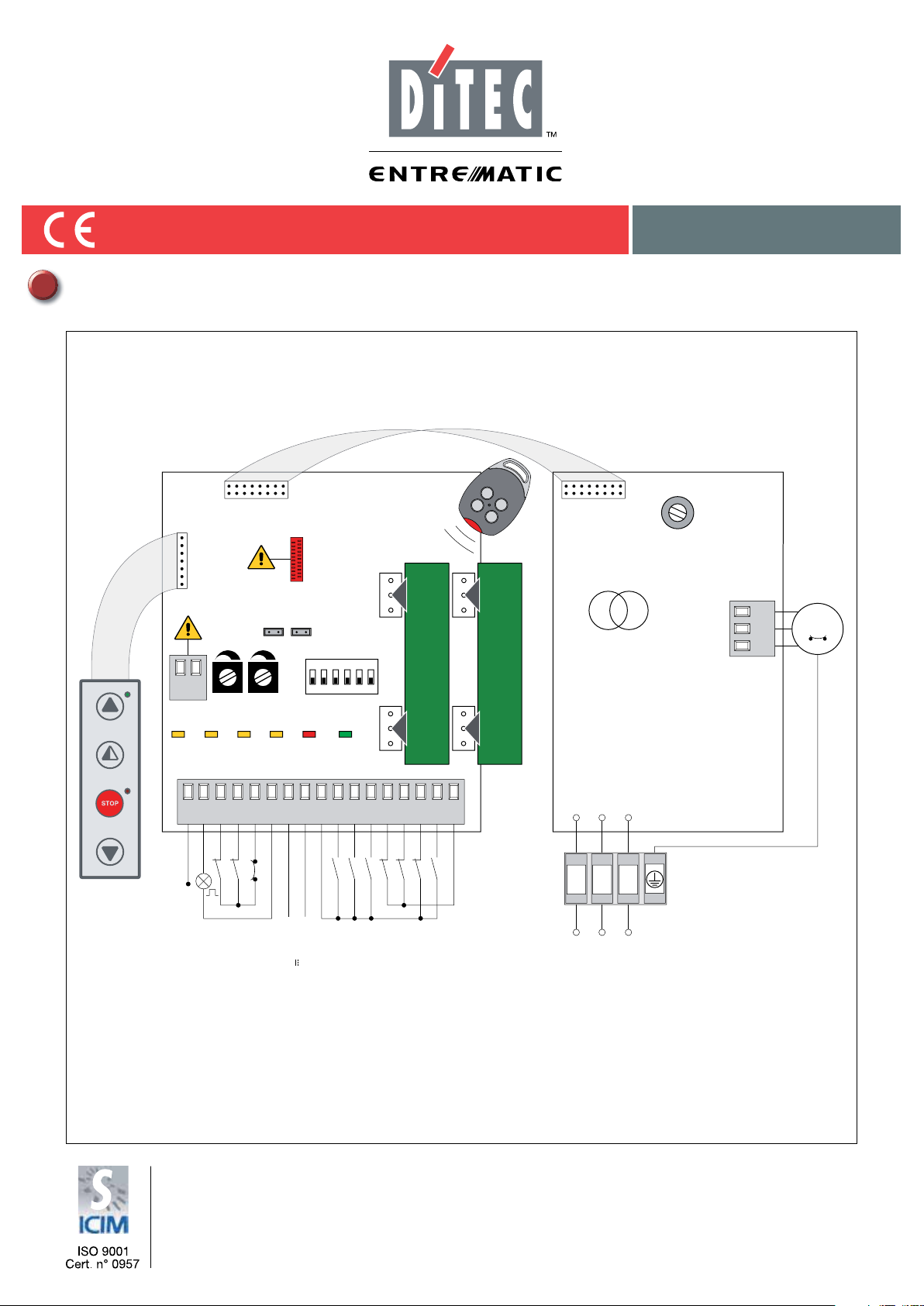
Installation manual for control panel for automations with one 400V three-phase motor.
IP1897EN
rev. 2012-03-22
PT3
PT4
EL07L EL07PW1
J7
DO NOT
DO NOT
USE
ON
+LK
-
USE
J1
COM
SO EO
ON
OFF
112 3 4 5 6
AUX1
GOL4
Transformer
AUX2
J2
F4
TCRP
11
12
17
17 14 12 11 00 0 1 1 2 3 4 6 8 92041
Flashing light
FUTURE USE
IN
SA
-
+
Closing limit switch
Opening limit switch
Output 24 V 0.5 A
Motor thermal protection
POWER
Closing
Opening
Safety stop
Automatic closing
Stop
Safety test
Partial opening
Safety re-opening
L1 L2 L3
F3 F2 F1
Power supply
Motor
3~
UWV
DITEC S.p.A.
Via Mons. Banfi, 3 - 21042 Caronno Pertusella (VA) - ITALY
Tel. +39 02 963911 - Fax +39 02 9650314
www.ditec.it - ditec@ditecva.com
Page 2
INDEX
Subject Page
1. *eneral safet\ precautions 3
2. EC declaration of conformit\ 4
3. Technical data 4
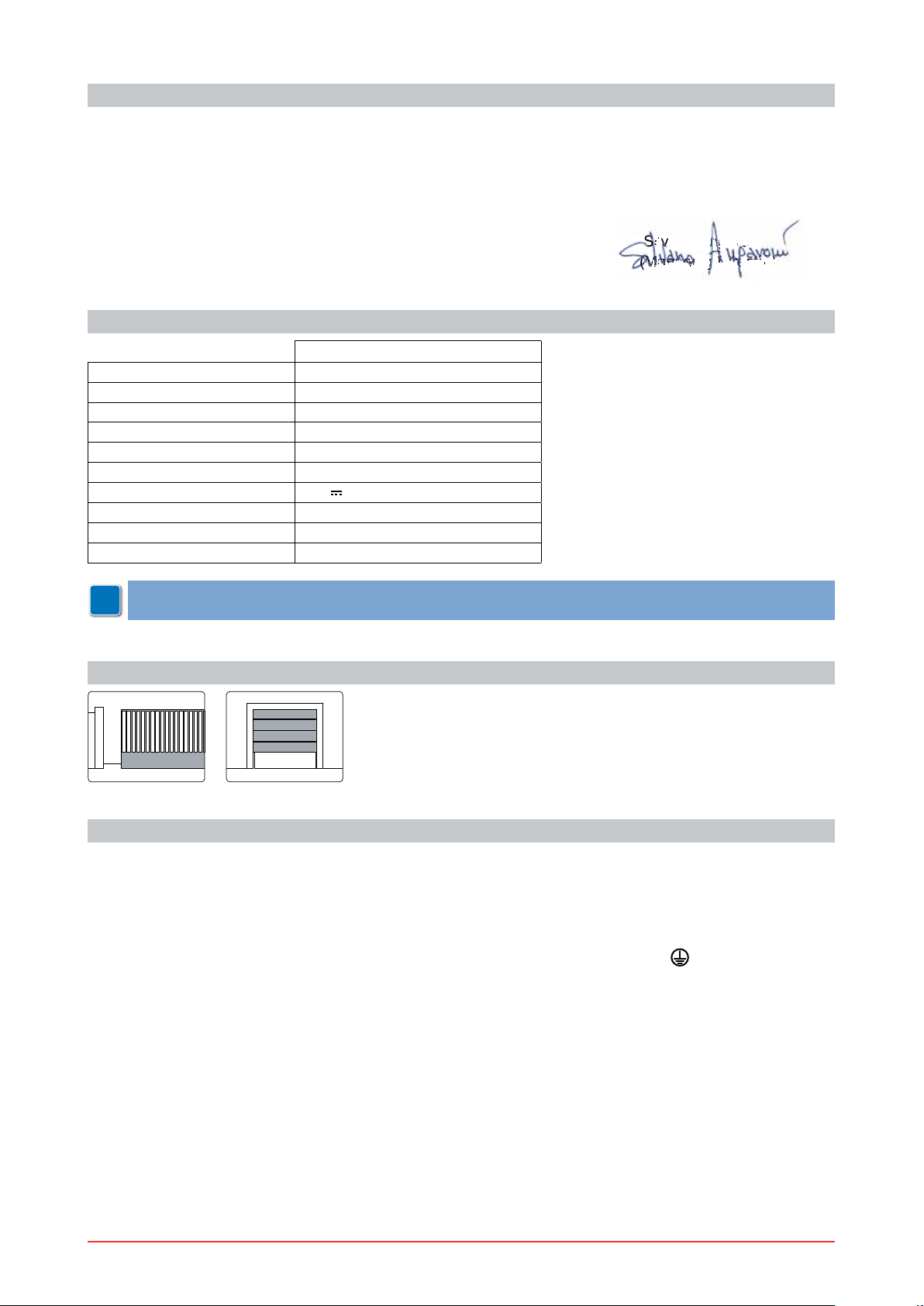
3.1 Applications
4. Connection of power suppl\ 4
5. Commands 5
5.1 62FA1-62FA2 self-controlled safet\ edJe
6. Outputs and accessories 6
7. A dj us t m e n t s 7
8. Start-up 8
9. TrouEleshootinJ 9
10. Example application for slidinJ Jates 10
11. Example application for sectional overhead doors 11
CAPTION
This s\mEol indicates instructions or notes reJardinJ safet\ issues which reTuire particular attention.
This s\mEol indicates informations which are useful for correct product function.
i
4
5
This s\mEol indicates instructions or notes intended for technical and expert personnel.
This s\mEol indicates operations not to Ee effected for not compromise the correct operation of the
STOP
automation.
This s\mEol indicates options and parameters which are onl\ availaEle with the indicated item.
This s\mEol indicates options and parameters which are not availaEle with the indicated item.
All right reserved
All data and speci¿cations have Eeen drawn up and checNed with the Jreatest care. The manufacturer cannot
however taNe an\ responsiEilit\ for eventual errors, ommisions or incomplete data due to technical or illustra-
tive purposes.
IP1897EN 2012-03-22
2
Page 3

1. GENERAL SAFETY PRECAUTIONS
This installation manual is intended for Tuali¿ed personnel onl\.
The installation, the power connections and the settinJs must Ee completed in conformit\ with *ood
:orNinJ Methods and with the reJulations in force.
Before installinJ the product, carefull\ read the instructions. Bad installation could Ee ha]ardous. The pacNaJinJ
materials (plastic, pol\st\rene, etc.) should not Ee discarded in the environment or left within reach of children,
as these are a potential source of ha]ard.
Before EeJinninJ the installation checN that the product is in perfect condition.
'o not install the product in explosive areas and atmospheres the presence of ÀammaEle Jas or fumes represents a serious threat to safet\.
The safet\ devices (photocells, sensitive edJes, emerJenc\ stop, etc.) must Ee installed taNinJ into account
the provisions and the directives in force, *ood :orNinJ Methods, the installation area, the functional loJic of
the s
\stem and the forces developed E\ the automation.
Before maNinJ power connections, checN that the ratinJ corresponds to that of the mains suppl\. A mul-
tipolar disconnection switch with a contact openinJ Jap of at least 3 mm must Ee included in the mains
suppl\. ChecN that upstream of the electrical installation an adeTuate residual current circuit EreaNer and an
overcurrent cut out are ¿tted.
:hen reTuested, connect the automation to an effective earthinJ s\stem carried out as indicated E\ current
safet\ reJulations.
'urinJ installation, maintenance and repair operations, cut off the power suppl\ Eefore openinJ the cover to
access the electrical parts.
To handle electronic parts, wear earthed antistatic conductive Eracelets. The manufacturer of the mo-
torisation declines all responsiEilit\ in the event of components which are not compatiEle with the safe
and correct operation of the product.
For repairs or replacements of products onl\ oriJinal spare parts must Ee used.
3
IP1897EN 2012-03-22
Page 4
2. EC DECLARATION OF CONFORMITY
Si
Si
Si
i
lv
ano An
Ja
Ja
JJaJa
Ja
J
J
J
J
ro
ni
D Dececto
Manufacturer: DITEC S.p.A.
Address: via Mons. Ban¿, 3 21042 Caronno P.lla (VA) - ITALY
declares that the control panel E1T is in conformit\ with the provisions of the followinJ EC directives:
EMC Directive 2004/108/EC;
Low VoltaJe Directive 2006/95/EC.
Caronno Pertusella, 13-12-2010 Silvano AnJaroni
(ManaJinJ Director)
3. TECHNICAL DATA
E1T
Power supply 400 Va 50 +]
F1 fuse F8A
F2 fuse F8A
F3 fuse F8A
F4 fuse F3,15A
Motor output 400 V~ 6 A
Accessories power supply 24 V
Temperature min -20 °C max +55 °C
Degree of protection IP55
Box dimensions 238x357x120
NOTE: the given operating and performance features can only be guaranteed with the use of DITEC
i
accessories and safety devices.
0,5 A
3.1 Applications
4. CONNECTION OF POWER SUPPLY
Fix the control panel permanentl\. Pass the caEles alonJ from the lower side of the container.
Before connectinJ the power suppl\, maNe sure the plate data correspond to that of the mains power suppl\.
An omnipolar disconnection switch with minimum contact Japs of 3 mm must Ee included in the mains suppl\.
ChecN that upstream of the electrical installation there is an adeTuate residual current circuit EreaNer and a
suitaEle overcurrent cutout.
8se a +075N-F 4*1,5 t\pe electric caEle and connect to the terminals L1, L2, L3,
automation.
Secure the caEle usinJ the special caEle clamp and remove the outer sheath near the terminal onl\.
MaNe sure there are no sharp edJes that ma\ damaJe the power suppl\ caEle.
Connection to the mains power suppl\, in the section outside the automation, is made with independent chan-
nels and separated from the connections to the control and safet\ devices.
IP1897EN 2012-03-22
4
(\ellow/Jreen) in the
Page 5

5. COMMANDS
Command Function Description
1
2 N.O. AUTOMATIC
CLOSING
1
3 N.O. OPENING :ith DIP1 ON, the closinJ of the contact activates the openinJ
STEP-BY-STEP :ith DIP1 OFF, the closinJ of the contact activates openinJ or
1
41
41
4 N.O. CLOSING The closinJ of the contact activates the closinJ operation.
6 N.C. SAFETY STOP All operations are stopped and/or ElocNed when the safet\ con-
8 N.C. REVERSE
SAFETY CONTACT
1 9 N.C. STOP The openinJ of the safet\ contact stops the current operation.
EMERGENCY
STOP
1
9 N.O. HOLD-TO-RUN
FUNCTION
1
20 N.O. PARTIAL
OPENING
0 11 N.C. CLOSING
LIMIT SWITCH
0
12 N.C. OPENING
LIMIT SWITCH
17 FUTURE USE
The permanent closinJ of the contact enaEles automatic closinJ.
operation.
closinJ operations in the followinJ seTuence: open-stop-closeopen.
NOTE: if automatic closing is enabled, the stop is not permanent
but lasts for a duration set by TC.
tact is opened.
The openinJ of the safet\ contact triJJers a reversal of motion
(re-openinJ) durinJ closinJ.
To enaEle the emerJenc\ stop function (e.J. with a speci¿c red
Eutton), connect the openinJ and closinJ controls to terminal 9
instead of terminal 1 (9-3, 9-4, 9-20).
The openinJ of the 1-9 contact enaEles the hold-to-run function.
- hold-to-run openinJ 1-3 >with DIP1 ON@;
- hold-to-run closinJ 1-4.
NOTE: any safety devices, automatic closing and plug-in cards
inserted in AUX1 and AUX2 are disabled.
The closinJ of the contact activates a partial openinJ operation
of the duration set with the RP trimmer.
Once the automation stops, the partial openinJ control performs
the opposite operation to the one performed Eefore stop.
The openinJ of the limit switch contact stops the closinJ operation.
The openinJ of the limit switch contact stops the openinJ operation.
WARNING: make a jumper for all the N.C. contacts if not in use. The terminals with the same number
are equal.
5.1 SOFA1-SOFA2 self-controlled safety edge
Command Function Description
SAFETY TEST Place the SOFA1-SOFA2 device into its housinJ for pluJ-in
cards AUX1-AUX2.
NOTE: connecting terminal 41 enables a safety edge test cycle
before every operation. If the test fails the 6A led Àashes and
the test is repeated.
nals 1-6 on the control panel (in series with the photocell output
contact, if installed).
Connect the output contact of device SOFA1-SOFA2 to termi-
SAFETY CONTACT
nals 1-8 on the control panel (in series with the photocell output
contact, if installed).
5
IP1897EN 2012-03-22
1
1
SOFA1-SOFA2
0411
6 N.C. SAFETY STOP Connect the output contact of device SOFA1-SOFA2 to termi-
8 N.C. REVERSE
Page 6

6. OUTPUTS AND ACCESSORIES
Output Value - Accessories Description
24 V 0.5 A
3 W
24 V
3 W
24 V
LAMPH
400 V~ 6 A
PT3 Membrane push-button panel. Starts the openinJ operation.
PT3 Membrane push-button panel. Causes the ElocNinJ of the move-
PT3PT4
1
1
0
01
-
+
AUX1
AUX2
COM
-
+LK
UWV
11
12
14
Accessories power supply. Power suppl\ output for external ac-
cessories, includinJ automation status lamp.
Open automation lamp. The liJht switches off when the automa-
tion is closed.
Closed automation lamp. The liJht switches off when the auto-
mation is open.
Flashing light. Activated durinJ openinJ and closinJ operations.
The control panel has two housinJs for pluJ-in cards such as a
radio receiver t\pe, maJnetic loops, etc.
PluJ-in card operatinJ is selected usinJ DIP1.
WARNING: the plug-in cards must be inserted and removed with
the power supply disconnected.
DO NOT USE
DO NOT USE
Three-phase motor. Connect the contact of the motor circuit
EreaNer in series to the limit switches.
NOTE: if the rotation direction of the motor is incorrect for the desired direction of movement, swap the L2 and L3 phases.
NOTE: connect the push-button panel connector to J7. Connect
the push-button panel to J7 rotated through 180° to activate the
closing operation.
ment.
J7
PT3
PT4
PT4
PT4
PT4
Membrane push-button panel. Starts the closinJ operation.
NOTE: connect the push-button panel connector to J7. Connect
the push-button panel to J7 rotated through 180° to activate the
closing operation.
ON
Membrane push-button panel. Starts the openinJ operation.
NOTE: the green LED on indicates the presence of the 24 V
power supply.
Membrane push-button panel. Starts the partial openinJ opera-
tion.
Membrane push-button panel. Starts and stops the STOP operation.
NOTE: the red LED on indicates that the STOP has been activated.
The Àashing red LED indicates that the safety devices have been
activated.
Membrane push-button panel. Starts the closinJ operation.
IP1897EN 2012-03-22
6
Page 7

7. A DJUSTMENTS
Description OFF ON
DIP1 Command 1-3 operation.
NOTE: it also sets operating mode of the
plugin cards connected on AUX1 and
AUX2.
DIP2 Restore automatic closing time. 50% 100%
DIP3 3 seconds preÀashing. DisaEled durinJ openinJ.
DIP4 Application type. SlidinJ Jate or sectional
DIP5 Dynamic brake. DisaEled. DO NOT USE
DIP6 FUTURE USE //
Description OFF ON
SO Reversal safety switch function. With the automation ElocNed,
EO DO NOT USE //
Trimmer Description
RP
Partial opening adjustment. From 0 to 30 s.
Step-E\-step. OpeninJ.
EnaEled for Eoth openinJ
EnaEled onl\ with automatic
and closinJ.
closinJ with TC !3 s.
DO NOT USE
overhead door.
With the automation ElocNed,
if the contact 1-8 or 41-8 is
open, it is possiEle to activate
the openinJ operation.
if the contact 1-8 or 41-8 is
open, an\ operation is im-
possiEle.
0 s 30 s
TC
Setting automatic closing time. From 0 to 120 s.
NOTE: after the activation of the stop command, once contact 1-9 has closed again,
0 s 120 s
the automatic closing is only activated after a total, partial or step-by-step opening
command.
LED On Flashing
17 FUTURE USE
12
11
IN
0-12 limit switch contact is open.
0-11 limit switch contact is open.
Receipt of command or chanJe in status of
a dip-switch.
/
/
/
SA At least one of the safet\ contacts is open. STOP operation activated
E\ push-Eutton panel PT4.
Safet\ test failure on SOFA1-SOFA2
device (terminal 41).
Operations count performed (onl\ when control panel is switched on):
= 1000 operations
= 10000 operations
POWER
Power suppl\ on. Current overload on
ÀashinJ liJht output.
ShortcircuitinJ of
the ÀashinJ liJht driver.
7
IP1897EN 2012-03-22
Page 8

8. START-UP
G
WARNING The operations in point 3 are performed without safety devices.
ARNIN
The trimmer can only be adjusted with the automation idle.
1- MaNe a jumper for the N.C. safet\ contacts.
2- Set DIP4=OFF.
3- Switch on and checN that the automation is operatinJ correctl\ with suEseTuent openinJ and closinJ
commands.
ChecN that the limit switches are activated.
NOTE: if the direction of rotation of the motor is incorrect for the desired direction of the automation, swap
the L2 and L3 phases.
4- Connect the safet\ devices (removinJ the relative jumpers) and checN the\ worN correctl\.
WARNING: check that the working forces exerted by the door wings are compliant with EN12453-EN12445
regulations.
5- If reTuired, activate automatic closinJ usinJ command 1-2 and adjust the time usinJ the TC trimmer.
6- If reTuired, activate partial openinJ usinJ command 1-20 and adjust the time usinJ the RP trimmer.
7- If reTuired, connect the radio receiver to the relative AUX connector, proJram the transmitters as descriEed
in the relative manual and checN that all elements function correctl\.
8- Connect an\ other accessories and checN the\ operate correctl\.
9- Once the start-up and checN procedures are completed, close the container.
NOTE: in the event of servicing or if the control panel is to be replaced, repeat the start-up procedure.
i
The operations in point 3 are performed without safety devices.
The trimmer can only be adjusted with the automation idle.
IP1897EN 2012-03-22
8
Page 9

9. TROUBLESHOOTING
Problem Possible causes Remedy
The automation does not
open or close.
External safet\ devices not
activatinJ.
No power.
(POWER led off).
Short circuited accessories.
(POWER led off).
Blown line fuses.
(POWER led off).
Safet\ contacts are open.
(SA led on).
Safet\ contacts not correctl\ connected
or SOFA1-SOFA2 self-controlled safet\
edJe not functioninJ correctl\.
(SA led ÀashinJ).
Release microswitch open (if present).
(11 and 12 led on).
The motor thermal overload switch is
open.
(11 and 12 led on).
Photocells are activated.
(SA led on).
The automatic closinJ does not worN.ChecN that contact 1-2 is closed.
Incorrect connections Eetween the
photocells and the control panel.
ChecN that the control panel is powered correctl\.
Disconnect all accessories from terminals 0-1 (voltaJe must Ee 24 V
reconnect one at a time.
Replace fuses.
ChecN that the safet\ contacts are
closed correctl\ (N.C.).
ChecN connections to terminals 6-8 on
control panel and connections to the
SOFA1-SOFA2 self-controlled safet\
edJe.
ChecN that the hatch is closed correctl\
and the microswitch maNes contact (if
present).
ChecN the continuit\ of the thermal
contact.
ChecN that the photocells are clean
and operatinJ correctl\.
Connect N.C. safet\ devices toJether in
series and remove an\ E
control panel terminal Eoard.
ridJes on the
) and
9
IP1897EN 2012-03-22
Page 10

10. EXAMPLE APPLICATION FOR SLIDING GATES
(FiJ. 10.1) When the control panel is used in applications
for slidinJ Jates:
- set DIP4=OFF;
- connect openinJ and closinJ limit switches N.C.
contacts to terminals 0-11-12.
With the aEove connections, when limit switches operate the winJ stops.
NOTE: if the SOFA1-SOFA2 self-controlled
safety edge is used, make the connections indi-
i
cated on page 5.
NOTE: it is possible to use the remote control
with s tep- by- s t ep function and, at the same time,
the terminal 3 with opening function, making the
i
connections indicated in ¿g. 10.2 and setting
DIP1=OFF.
ON
OFF
123 4 5 6
DIP4=OFF
17 14 12 11 00 0 1 1 2 3 4 6 8 92041
Closing limit switch
Opening limit switch
Motor thermal protection
ON
OFF
123 4 5 6
DIP1=OFF
DIP4=OFF
FiJ. 10.1
17 14 12 11 00 0 1 1 2 3 4 6 8 92041
Closing limit switch
Opening limit switch
Motor thermal protection
FiJ. 10.2
IP1897EN 2012-03-22
10
Page 11

11. EXAMPLE APPLICATION FOR SECTIONAL OVERHEAD DOORS
(FiJ. 11.1) When the control panel is used in applications
for sectional overhead doors:
- set DIP1=ON;
- set DIP2=ON;
- set DIP4=OFF;
- connect openinJ and closinJ limit switches N.C.
contacts to terminals 0-11-12.
NOTE: to use the control panel in hold-to-run
i
mode, disconnect terminal 9.
In this case, the openinJ command (1-3, 1-20) and the
closinJ command (1-4) operate onl\ if Nept pressed, if
released the automation will stop. Automatic closinJ
and radio remote controls are disaEled.
(FiJ. 11.2) If the SOFA1-SOFA2 self-controlled safet\
edJe is connected on closinJ, maNe the connections
indicated in the ¿Jure.
WARNING: if the closing edge remains pressed
on the Àoor, set SO=OFF.
NOTE: membrane push-button panels PT3 ¿g.
11.1 or PT4 ¿g. 11.2 can be connected to the
i
connector J7.
PT3
J7
ON
OFF
123 4 5 6
DIP1=ON
DIP2=ON
DIP4=OFF
17 14 12 11 00 0 1 1 2 3 4 6 8 92041
Closing limit switch
Opening limit switch
SO=OFF
SO
J7
Motor thermal protection
ON
OFF
123 4 5 6
FiJ. 11.1
DIP1=ON
DIP2=ON
DIP4=OFF
ON
FiJ. 11.2
17 14 12 11 00 0 1 1 2 3 4 6 8 92041
Closing limit switch
Opening limit switch
Motor thermal protection
SOFA1-SOFA2 safety test
11
IP1897EN 2012-03-22
Page 12

TM
DITEC S.p.A. Via Mons. Ban¿, 3 21042 Caronno P.lla (VA) Ital\ Tel. +39 02 963911 Fax +39 02 9650314
www.ditec.it ditec@ditecva.com
DITEC BELGIUM LO.EREN Tel. +32 9 3560051 Fax +32 9 3560052 www.ditecEelJium.Ee DITEC DEUTSCHLAND OBERURSEL
Tel. +49 6171 914150 Fax +49 6171 9141555 www.ditec-Jerman\.de DITEC ESPAÑA ARENYS DE MAR Tel. +34 937958399
Fax +34 937959026 www.ditecespana.com DITEC FRANCE MASSY Tel. +33 1 64532860 Fax +33 1 64532861 www.ditecfrance.com
DITEC GOLD PORTA ERMESINDE-PORTUGAL Tel. +351 22 9773520 Fax +351 22 9773528/38 www.Joldporta.com DITEC SWITZERLAND
BALERNA Tel. +41 848 558855 Fax +41 91 6466127 www.ditecswiss.ch DITEC ENTREMATIC NORDIC LANDSKRONA-SWEDEN
Tel. +46 418 514 50 Fax +46 418 511 63 www.ditecentrematicnordic.com DITEC TURCHIA ISTANBUL Tel. +90 21 28757850
Fax +90 21 28757798 www.ditec.com.tr DITEC AMERICA ORLANDO-FLORIDA-USA Tel. +1 407 8880699 Fax +1 407 8882237
www.ditecamerica.com DITEC CHINA SHANGHAI Tel. +86 21 62363861/2 Fax +86 21 62363863 www.ditec.cn
 Loading...