

Page 1

Ditec DAS107
Automation for
sliding doors
(Original instructions)
www.entrematic.com
IP2239EN
Technical Manual
Page 2

4
IP2239EN - 2016-05-11
Contents
Key
Subject Page
1. General safety precautions 5
2. List of tools 6
3. Contents of the kit 7
4. Standard installation 9
5. Technical specifications 10
6. Assembling the automation 10
7. Installing the automation 18
8. Electrical connections 21
9. Adjustments 24
10. Start-up 25
11. Example of a connection with radar and photocells 29
12. Troubleshooting / Alarms 30
13. Routine maintenance plan 32
i
This symbol indicates instructions or notes regarding safety, to which special attention must be paid.
This symbol indicates useful information for the correct functioning of the product.
All the rights concerning this material are the exclusive property of Entrematic Group AB.
Although the contents of this publication have been drawn up with the greatest care, Entrematic Group AB cannot be held responsible in any way for any damage caused by mistakes or omissions. We reserve the right
to make changes without prior notice.
Copying, scanning or changing in any way is expressly forbidden unless authorised in writing by Entrematic
Group AB.
Page 3

5
IP2239EN - 2016-05-11
1. General safety precautions
This assembly and installation manual is intended exclusively for the use of qualified personnel.
Installation, electrical connections and adjustments must be performed by qualified personnel, in accordance with Good Working Methods and in compliance with the current regulations.
Read the instructions carefully before installing the product.
Incorrect installation could be dangerous.
The packaging materials (plastic, polystyrene, etc.) should not be discarded in the environ-
ment or left within reach of children, as they are a potential source of danger.
Before installing the product, make sure it is in perfect condition.
Do not install the product in explosive areas and atmospheres: the presence of inflammable
gas or fumes represents a serious safety hazard.
Before installing the motorisation device, make all the necessary structural modifications to
create safety clearance and to guard or isolate all the crushing, shearing, trapping and general
hazardous areas.
Make sure the existing structure is up to standard in terms of strength and stability. The motorisation device manufacturer is not responsible for failure to observe Good Working Methods
when building the frames to be motorised, or for any deformations during use.
The safety devices (photocells, safety edges, emergency stops, etc.) must be installed taking
into account the applicable laws and directives, Good Working Methods, installation premises,
system operating logic and the forces developed by the motorised door or gate.
The safety devices must protect against crushing, cutting, trapping and general danger areas
of the motorised door or gate.
Display the signs required by law to identify hazardous areas.
Each installation must bear a visible indication of the data identifying the motorised door
or gate.
When necessary, connect the motorised door or gate to an effective ear thing system that complies with the current safety standards.
During installation, maintenance and repair operations, cut off the power supply before opening
the cover to access the electrical parts.
The automation protection casing must be removed by qualified personnel only.
The electronic parts must be handled using earthed antistatic conductive arms. The
manufacturer of the motorisation device declines all responsibility if component parts
not compatible with safe and correct operation are fitted.
Only use original spare parts when repairing or replacing products.
The installer must supply all information concerning the automatic, manual and emergency operation of the motorised door or gate, and must provide the user with the operating instructions.
Failure to respect the information given in this manual
may cause personal injury or damage to the device.
Keep these instructions for future reference
Page 4

6
IP2239EN - 2016-05-11
2. List of tools
Tape measure
Pencil
10mm open-end spanner
3mm Allen key
10mm embedded hexagon Allen key
TORX T20 spanner
Drill
Scissors
Saw
Page 5

7
IP2239EN - 2016-05-11
3. Contents of the kit
1
2
3
4
5
6
7
8
9
10
9
10
11
12
2
13
7m
x2
x2
x2
TX RX
x2
16
1
17
19
8
14
15
18
A
B
C
Page 6

8
IP2239EN - 2016-05-11
Ref. Description Qty
BOX - A 1 Beam profile L = 4400mm 2
BOX - B 14 Cover profile L = 4400mm 2
BOX - C 2 End stop 2
3 Power supply unit 1
4 Gearmotor 1
5 Control panel 1
7 Carriage 4
8 Belt 1
9 Belt connection bracket 2
10 Belt restrainer hook 2
12 Belt transmission 1
13 Carriage anti-derailing device 4
15 Cover end plate 2
16 Function selector switch COM500MKS 1
17 Pair of photocells 2
18 Cover supports 2
19 Cover restraints 5
Connection cables 3
Cable fastener 10
Cable fastener ties 15
M6x16 screws 4
Ditec Entrematic logo 1
Technical manual 1
User manual 1
OPTIONAL ACCESSORIES
6 Batteries DAS901BAT1 1
11
Anti-panic block DAS801LOKA 1
Standard block DAS801LOK complete with release cord 1
The given operating and performance features can only be guaranteed with the use of DITEC
Entrematic accessories and safety devices.
Unless otherwise specified, all measurements are expressed in mm.
Page 7

9
IP2239EN - 2016-05-11
Ref. Code Description
1 Ditec DAS107 Automation for sliding doors
2 COM500MKS Function selector switch
3 Photocells
4 Opening sensors
A
Connect the power supply to an approved omnipolar switch with an opening distance of the contacts of
at least 3mm (not supplied). The connection to the mains must be made via an independent channel,
separated from the connections to command and safety devices.
4. Standard installation
1
4
2
3
A
Page 8
10
IP2239EN - 2016-05-11
Ditec DAS107
Power 110V~ ÷ 220V~ ±10% ; 50/60 Hz
Rated power max. 100W
Max. load 1 door wing 120kg
Max. load 2 door wings 80kg / door wing
Temperature -20°C / +50°C
Degree of protection IP20
Power supply for accessories 24V
1A
Max speed 0,5 m/s (1 wings) ; 1,0 m/s (2 wings)
Intermittance S3=100%
Minimum number of maneuvers in AVERAGE
conditions of use
1.000.000 cycles* (2 wings x80 kg/1 wing x100 kg)
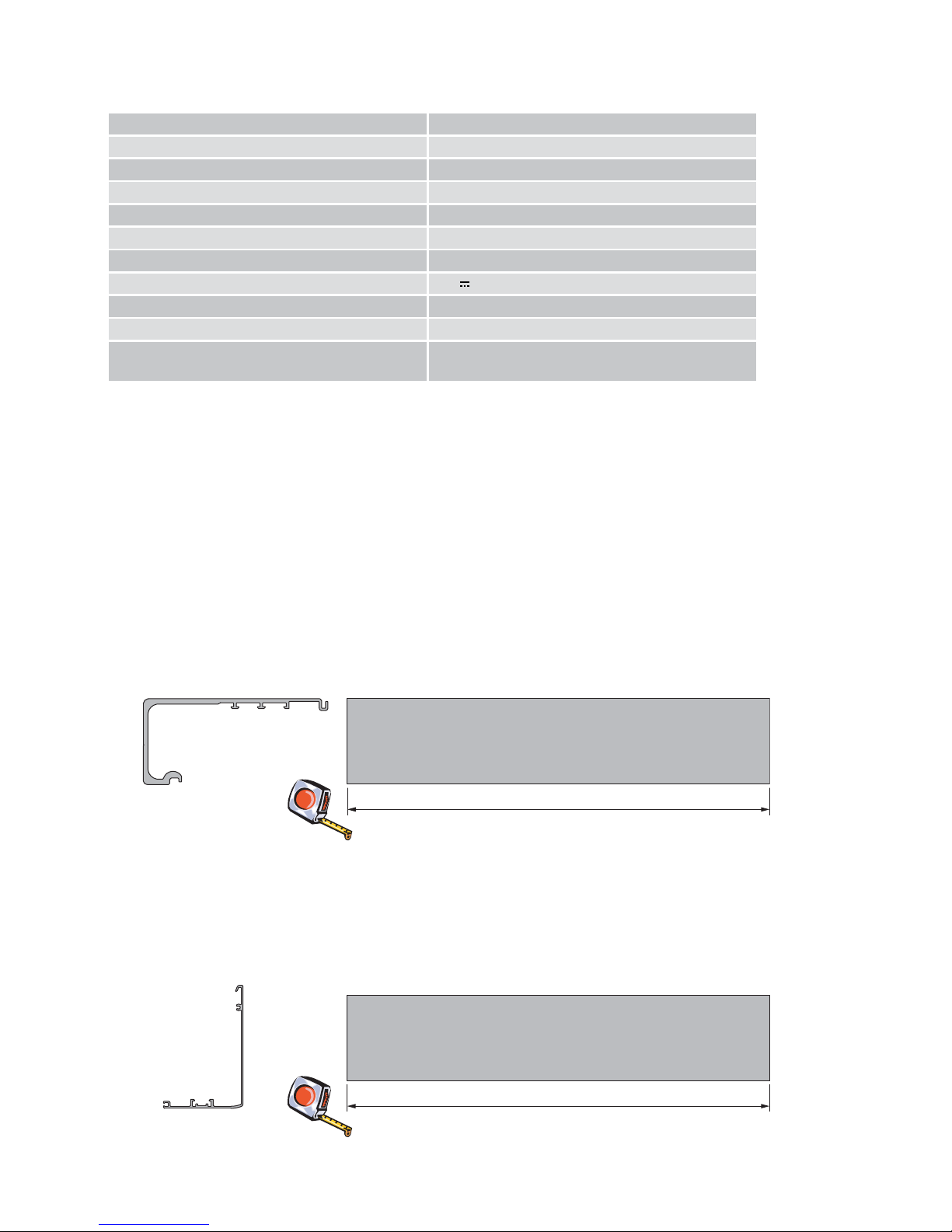
5. Technical specifications
6. Assembling the automation
Cut the beam profile to the size shown.
To make it easier to fix the beam to the wall, it is useful to drill holes of Ø 8mm every 400mm.
NB: remove any cutting residue from the aluminium, cleaning the carriage slide guides in particular.
Cut the cover profile to the size shown.
* test carried out by Entrematic Italy laboratory
LT-14
6.1 Cutting and preparing the beam
6.2 Cutting and preparing the cover
LT-10
Page 9

11
IP2239EN - 2016-05-11
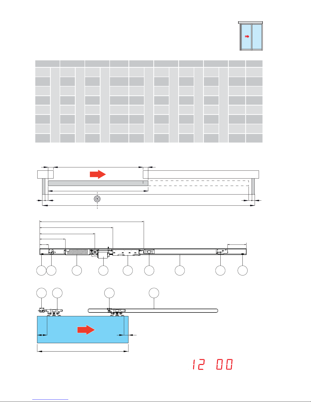
Automation with two door wings
LT PL LM B C D E F S
*2400
2PL+2S+20+400
940
LT/2-S-210
520
PL/2+S
80
C-340
420
LT/2-PL/2-310
580
C+160
960
C+540
350
(LT/2)-(PL/2)+380
50
*2600 1040 570 130 470 630 1010 400 50
*2800 1140 620 180 520 680 1060 450 50
*3000 1240 670 230 570 730 1110 500 50
2800
2PL+2S+20
1340
LT/2-S-10
720 80 420 580 960 350 50
3000 1440 770 130 470 630 1010 400 50
3300 1590 845 205 545 705 1085 475 50
3600 1740 920 280 620 780 1160 550 50
4000 1940 1020 380 720 880 1260 650 50
4400 2140 1120 480 820 980 1360 750 50
PL
LM LM
LT
55
55
SS
OPEN
OPEN
B F
C
D
E
3 4 5 6
1
121122
The values shown here are calculated by considering an overlap of S=50
*Lenght increased compared to the obatined opening passage due to power supply dimension.
53
LM
OPEN
53
53
53
LM
OPEN
9 9 8 7
Page 10
12
IP2239EN - 2016-05-11
Automation for a single door wing with right-hand opening
LT PL LM A B C D E F S
2000
2PL+3S+20
915
(LT-3S-20)/2
1015
PL+2S
30 370
C-340
710
LT-LM-325+S
870
C+160
1250
C+540
40 50
2200 1015 1115 30 470 810 970 1350 40 50
2600 1215 1315 30 670 1010 1170 1550 40 50
3000 1415 1515 30 870 1210 1370 1750 40 50
3300 1565 1665 30 1020 1360 1520 1900 40 50
3600 1715 1818 30 1170 1510 1670 2050 40 50
4000 1915 2015 30 1370 1710 1870 2250 40 50
4400 2115 2215 30 1570 1910 2070 2450 40 50
The values shown here are calculated by considering an overlap of S=50
PL
LM
LT
S
55 55
S
OPEN
B
A
F
C
D
E
3 4 5 6 12112 21
SET MENU =
53110
LM
OPEN
7 9 811
Page 11

13
IP2239EN - 2016-05-11
Automation for a single door wing with left-hand opening
LT PL LM A B C D E F S
2000
2PL+3S+20
915
(LT-3S-20)/2
1015
PL+2S
40 1780
C+340
1440
LT-LM-15+420+S
1280
C-160
900
C-540
120 50
2200 1015 1115 40 1880 1540 1380 1000 120 50
2600 1215 1315 40 2080 1740 1580 1200 120 50
3000 1415 1515 40 2280 1940 1780 1400 120 50
3300 1565 1665 40 2430 2090 1930 1550 120 50
3600 1715 1815 40 2580 2240 2080 1700 120 50
4000 1915 2015 40 2780 2440 2280 1900 120 50
4400 2115 2215 40 2980 2640 2480 2100 120 50
The values shown here are calculated by considering an overlap of S=50
PL
LM
LT
S
5555
S
OPEN
B
A
F
C
D
E
3 4 5 6 72 21 11
11053
LM
OPEN
7 98 11
Page 12

14
IP2239EN - 2016-05-11
6.3 Assembling the carriages
Assemble the anti-derailing wheel [13] on the carriages, in the position shown in the figure.
13
7
6.4 Assembling the transmission
Position the transmission as shown at page 11, 12, 13 in position [F].
12
Page 13

15
IP2239EN - 2016-05-11
6.5 Assembling the belt
Example for an automation with two door wings
Insert the belt in the motor pulley (to make this operation easier, turn the pulley).
Wrap the belt around the transmission.
Join the belt ends in line with the belt connection brackets [9], and lock it in place with the belt
restrainer hook [10]. Cut off any excess.
9
7
10
Page 14

16
IP2239EN - 2016-05-11
6.6 Installing the door wing block (optional)
6.7 Installing the end stops
The door wing blocking device can be fitted to keep the door closed.
The automation automatically recognises the blocking device and acts properly.
- Fasten the door wing blocking device inside the box by means of the screws supplied.
- Place the door wing in the closure position.
- Check that, with the door closed, the block is resting correctly on the block hook-up bracket,
preventing the door from sliding.
- Make the electrical connections as explained in chapter 8.1.
For more information, refer to the blocking device manual.
Insert the end stops [2] in the beam profile and fix them in place.
Refer to the images on pages 11-12-13 for the correct positioning.
22
11
2
LEFT RIGHT
Page 15

17
IP2239EN - 2016-05-11
6.8 Assembling the cover supports
Insert the cover supports [19] in the cover profile and fix them in place (A) near the end plate, as
shown in the figure.
Use the screws supplied to fix the heads to the casing profile, as shown.
Insert the cover restraints (20) along the cover profile.
To fix the cover to the beam, push up the support 18, insert it in the beam and fix it by screws (B).
18
(x2)
(x5)
19
18
B
A
fascetta
stringicavo
15
18
19
Insert the cover support (18) at the ends of the guide of the cover.
Screw the end plate (15) to the cover.
cable fasteners
cable
fasteners
ties
Page 16

18
IP2239EN - 2016-05-11
7.1 Beam fastening
7. Installing the automation
HM = H-40
H = HM+40
65
65
10
140
120
+/-7
+/-6
• Establishing the fixing height from the highest point of the finished floor.
• Measure the height, including the door wing connection. The installation height is equal to
HM+40mm.
• Fix the beam profile in the points indicated, using wall plugs and bolts. NB: the heads of the
screws/bolts must not be more than 6.5mm.
• Distribute the fixing points every 400mm, and at different heights if necessary.
• Make sure the top surface of the beam is perpendicular with the floor and not deformed
lengthwise with the shape of the wall. If the wall is not straight and smooth, iron plates must
be fixed to it and then the guide in turn fixed to the plates.
NOTE: the maximum space for the wings between cover and beam is 65mm.
WARNING: The fastening of the beam to the wall must be suitable in order to sustain the weight
of the door wings.
Page 17

19
IP2239EN - 2016-05-11
7.2 Installing and adjusting the door wings
Fix the carriages to the door wings as shown in the figure.
53
110
53
53
53
53
53
110
OPEN
OPEN
OPEN
OPEN
AUTOMATION WITH TWO DOOR WINGS
AUTOMATION WITH ONE DOOR WING WITH
RIGHT-HAND OPENING
AUTOMATION WITH ONE DOOR WING WITH
LEFT-HAND OPENING
Page 18

20
IP2239EN - 2016-05-11
7.3 Adjusting the belt
The vertical position of the door wing can be adjusted, as shown in the figure.
Loosen the screws [A] and adjust the height with the screws [B].
Move the door wing manually to make sure the movement is free and without friction, and that all
the wheels (including the anti-derailing wheel) are resting on the guide.
A
B
+/- 6
Adjust the belt tension by means of the screw [A].
WARNING: incorrect adjustment impairs the correct functioning of the automation.
A
I
I
I
I
I
I
I
I
I
I
I
I
I
I
I
I
I
I
Torque:
for opening passage PL ≤ 1400mm --> 0,5 Nm
for opening passage PL > 1400mm --> 1,0 Nm
Page 19

21
IP2239EN - 2016-05-11
8. Electrical connections
Connect the automation to an efficient earthing system that complies with current safety
standards.
During installation, maintenance and repair operations, cut off the power supply before opening
the cover to access the electrical parts.
The automation protection casing must be removed by qualified personnel only.
An omnipolar disconnection switch with a contact opening distance of at least 3 mm must be
fitted on the mains supply.
Check there is an adequate residual current circuit breaker and overcurrent cut-out upstream
of the electrical system.
Make sure the yellow/green conductor is at least 3 mm longer than the brown and blue conductors.
Install an electric switch next to the automatic system.
• Connect an electric cable – type H05RN-F 3G1,5 or H05RR-F 3G1,5 – to the terminals L
(brown), N (blue),
(yellow/green) on the power supply connector.
Make sure there are no sharp edges that may damage the power supply cable.
If the power cable is damaged, have it replaced by the manufacturer or qualified personnel.
• Connect the power cable [1] to the terminal board [2].
• Connect the connection cable [3] to the power supply unit [4].
1
3
2
NL
4
Page 20

22
IP2239EN - 2016-05-11
Make the connections indicated.
Output Description
A
Power supply unit connection
B
Motor connection
C
Encoder connection
green LED
D
Function selector switch connection
For connecting COM500MKS selectors up to a 50m max distance.
E
Connection of battery kit DAS901BAT1 (12V)
To charge the batteries, connect the mains power and the battery kit at
least 30 minutes before starting the system.
With the mains power supply off, the automation will carry out an opening operation at low speed and remains open ( except when program
selector in “door closed” position)
WARNING: for charging purposes, the battery kit must be connected
to the control panel at all times. Periodically check the efficiency of
the battery kit.
NOTE:
Battery type: 12V, 1,2mAh NiMH.
If a different type of battery is used it can damage!
Power supply
Motor
Control panel
COM500MKS
DAS901BAT1 (12V)
(optional)
A
D
E
C
B
Page 21

23
IP2239EN - 2016-05-11
7
6
5
4
3
2
1
14
13
12
11
10
9
8
17
16
15
20
19
18
NON USARE
Blocco
(+) Blocco
(+) 24 V
Apertura lato interno
(-) 0 V
(+) 24 V
NON USARE
Apertura a chiave
Sensore di presenza centrale 2
Monitoraggio apertura lato interno
Sensore di presenza centrale 1
(-) 0 V
(+) 24 V
NON USARE
Apertura lato esterno
NON USARE
NON USARE
NON USARE
Ponticellare i contatti N.C. se non utilizzati
(-) 0 V
collegamento blocco
}
8.1 Control panel commands
8.1.1 Commands
Contact Description
1
5 N.O.
OUTER SIDE
OPENING
Connect the external sensor.
The closure of the contact activates the door opening operation.
1
-
7
+
POWER SUPPLY
TO
ACCESSORIES
Power supply to the external sensor.
8
9 N.C.
REVERSAL
SAFETY
CONTACT 1
Connect safety photocell and inner safety sensor contact.
8
11 N.C.
REVERSAL
SAFETY
CONTACT 2
Connect safety photocell and outer safety sensor contact.
8
12 N.O. KEY OPENING
The closure of the contact via a key command activates an opening operation and a closure after time selected by menu 04.Can
be used for opening in night/CLOSED mode. In presence of power supply, a command 8-12 opens the door partially ( see menu
11) and closes after time selected by menu 04. In the absence of
a power supply, a command 8-12 causes the reactivation of the
battery for the time needed to carry out a total opening operation.The door remain in open position and the battery disconnected from control unit.
Jumper the unused NC contacts
DO NOT USE
DO NOT USE
DO NOT USE
DO NOT USE
Blocking device
Blocking device
]
blocking device connection
Opening - inner side
Key opening
Safety photocell 2
Safety photocell 1
Outer side opening
DO NOT USE
DO NOT USE
DO NOT USE
NOTE: Power supply output for
external accessories 24V 1A.
The maximum absorption of 1A
corresponds to the sum of all
terminals power supply output.
Page 22

24
IP2239EN - 2016-05-11
9. Adjustments
• 1 UP: To step up in parameter or value menu;
• 2 SELECT: Enters into parameters or value menu and program a value into menu;
• 3 DOWN: To step down in parameter or value menu;
• 4 LEARN/EXIT:
a) LEARN has 2 functions:
- Pushing it for more than 2 seconds the display show “L” for enable a learning phase.
- Pushing it for more than 10 seconds the displat show “L” for return to default factory set
parameters .
b) EXIT jumps out from value menu without saving or parameter menu
The two-digit display show when the operator is powered.
1
2
3
4
LEARN / EXIT SELECT
UP
DOWN
LEARN / EXIT
UP
SELECT
DOWN
8 14
+
POWER SUPPLY
TO
ACCESSORIES
Power supply to the photocells.
15 16 N.O.
OPENING -
INNER SIDE
Connect the internal sensor.
The closure of the contact activates the door opening operation.
15
-
17
+
POWER SUPPLY
TO
ACCESSORIES
Power supply to internal sensors.
18
19
BLOCKING
DEVICE
CONNECTION
Output for connecting an electro-mechanical block (optional).
The blocking device is automatically selected during the
learning phase (see parameter
)
9.1 Adjusting the parameters
1. Press key 2-SELECT to visualize the first parameter.
2. Press key 1-UP or key 2-DOWN to select the required parameter.
3. Press key 2-SELECT again to view the value of the selected parameter. The value will flash
twice.
4. Press key 1-UP or key 2-DOWN again to set a permitted parameter value.
5. Press key 2-SELECT to confirm the selected value.
6. Press key 4-LEARN/EXIT to quit without making any further modifications.
7. Press key 4-LEARN/EXIT again to quit the parameter selection. The display will show .
The display goes back to normal operation after 3 min of inactivity.
9.2 Restoring the factory settings
To restore the factory settings, press key 4-LEARN for 10 s. The display will flash with . The
successful restoration of the predefined parameters is confirmed by .
Page 23

25
IP2239EN - 2016-05-11
Start-up must be carried out in the following order when the operator is installed
To allow a correct learning of door weight, the “learning phase” must performed with door leaf
installed.
• Connect the accessories and jumper the N.C contact 8-9 and 8-11 if not used;
• Connect the mains power supply to the control unit;
• Select the opening direction by menu 12;
• Connect the battery kit DAS901BAT1 if present;
• Push the learn button for 2 seconds and release it when there is a flashing “L” in the display.
During the learning phase, the following accessories/parameters are automatically detected:
• Batteries
• Blocking device and type of blocking device
• Measurement of the passage opening
• Calculation of the door wing weight
When the learn is finished the display can show parameter 67. It is necessary to confirm the
number of installed wings:
1) press 2-SELECT
2) press 2-SELECT again. The value 67 will flashes
3) press 1-UP or 2-DOWN to select the required value
4) press 2-SELECT to confirm the selected value
5) press 4-LEARN for more than 2 s to return the display “on” mode. After 2 s the automation
closes and is ready for normal operation.
NOTE:
If the door cannot perform a correct learning phase due to mechanical reason the display could
show menu numbers messages that are not present in the standard menu. Remove the mechanical obstacles and restart again the learning sequence.
If necessary, you can adjust the following main parameters:
Opening speed
Closing speed
Automatic closing time
Partial opening
Opening direction
Type of program performance
Selection of number of wings
Make sure the installation complies with the current regulations and the essential requisites laid
down by the relevant authorities.
10. Start-up
Page 24

26
IP2239EN - 2016-05-11
10.4 Description of the parameters
i
In the “INSTALLATION SETTINGS” column you can note the modified setting values.
Display Description Factory setting
Installation
setting
Opening speed selection (10÷70; 10= 10cm/s; 70= 50cm/s)
Sets the maximum opening speed.
Closing speed selection (10÷70; 10= 10cm/s; 70= 50cm/s)
Sets the maximum closing speed.
AUTO
Automatic closing time selection (00÷60 s)
Adjusts the time during which the automation remains open
following an internal or external opening command.
Selection of automatic closing time after a “KEY” command
(00÷60 s)
Adjusts the time during which the automation remains open
following a key opening command "KEY".
Block type selection (00÷05)
00 = no blocking device
01 = DO NOT USE
02 = DO NOT USE
03 = anti-panic blocking device
04 = standard blocking device
05 = DO NOT USE
AUTO
Closure thrust before opening operation (00÷01)
00 = Disabled
01 = Enabled
If this function is enabled (01), the automation applies a closure thrust to guarantee the correct release on the opening
of the electric lock, if the selector is set on CLOSED DOOR
or ONE WAY.
AUTO
Configuration of photocells 1 (00÷01)
00 = NO
01 = NC
Configuration of photocells 2 (00÷01)
00 = NO
01 = NC
Partial opening selection (00÷99%)
Opening direction selection (00÷01)
The opening direction is determined by the position of the
belt connecting bracket.
00 = right hand opening for single door wing automation.
01 = left hand opening for single door wing automation and
for double door automations.
Acceleration and braking performance (01÷05)
01 = minimum performance
05 = maximum performance
Page 25

27
IP2239EN - 2016-05-11
Display Description Factory setting
Installation
setting
Selection of the batter y (00÷01)
00 = No battery
01 = 12V
AUTO
Adjustment of the opening delay with blocking device
(00÷99 s x 0.1)
Adjusts the opening delay time when a blocking device is installed, if the selector is set on CLOSED DOOR or ONE-WAY.
Close kick force
The force applied from the operator to the door leaf during
the close kick ( 00-19N x10).
Selection of number of wings (00÷01)
00 = Automation with one door wing
01 = Automation with two door wings
TO
BE SET
Page 26

28
IP2239EN - 2016-05-11
11. Example of connection
7
6
5
4
3
2
1
14
14
14 +24V
-24V
+24V
-24V
NPN
13
12
11
10
9
9
8
8
8
17
16
15
1515 16 17
71
INSIDE
SENSOR
RX
TX
24 V
+
-
15
OUTSIDE
SENSOR
24 V
+
-
INNER
SENSOR
OUTER
SENSOR
11.1 Example of connection with opening radar and photocell
INNER SENSOR
OUTER SENSOR
Photocells
Page 27

29
IP2239EN - 2016-05-11
11.2 Example of connection with opening + safety sensors PASAA2
PASAA2
PASAA2 INNER SENSOR
White
Brown
Green
Yellow
Pink (+)
Blue (-)
Red (+)
Black (-)
17
15
16
15
9
15
not connected
not connected
10 11 12 14
ON
White
Brown
Green
Yellow
Pink (+)
Blue (-)
Red (+)
Black (-)
17
15
5
15
11
15
PASAA2 OUTER SENSOR
not connected
not connected
Set the selection DIP switches on selector PASAA2 as shown below:
If used also photocell in combination with sensors:
• not connect the blue wire of sensor to terminal15;
• not connect the NPN wire of photocell receiver to terminal 9;
• connect the blue wire of sensors and the NPN wire of receiver togheter.
NOTE: the safety sensors work in normal mode, without possibilities of the testing of the safety
contact.
Page 28

30
IP2239EN - 2016-05-11
11.3 Example of connection with opening +safety sensors
PAS024AS
PAS024AS
PAS024AS INNER SENSOR
Green (+)
Brown (-)
Yell ow
White
Pink
Grey
Red (+)
Blue (-)
17
15
9
16
15
15
17
15
PAS024AS OUTER SENSOR
Green (+)
Brown (-)
Yell ow
White
Pink
Grey
Red (+)
Blue (-)
17
15
11
5
15
15
17
15
If used also photocell in combination with sensors:
• not connect the grey wire of sensor to terminal15;
• not connect the NPN wire of photocell receiver to terminal 9;
• connect the grey wire of sensors and the NPN wire of receiver togheter.
NOTE: the safety sensors work in normal mode, without possibilities of the testing of the safety
contact.
Page 29

31
IP2239EN - 2016-05-11
12. Troubleshooting / alarms
12.1 Alarms
Problem Solution
The automation doesn't open and
the motor doesn't start up
Check and change the functions selector switch settings.
Make sure there are no objects on the sensor's detection path.
Check the power supply switch inside the building.
The motor starts up but the automation doesn't open
Check any locks, releasing them if necessary.
Make sure there are no objects hindering the opening of the automa-
tion.
The automation doesn't close Check and change the functions selector switch settings.
Make sure there are no objects on the sensor's detection path.
The automation opens and closes
by itself.
Make sure there are no moving elements on the sensor's detection
area.
• The control panel display shows error signals.
• During normal operation, the display shows .
• If the display is switched off, check the mains power supply and the power cable, then RESET
from the function selector switch. Alternatively, disconnect the power supply and then reconnect it. If the problem persists, replace the control panel or power supply unit.
• When there is an alarm, the display alternates the error type (e.g. - Motor error) with a
2-figure number indicating the specific error (e.g. - Encoder error).
• If there are several errors, they will be visualised in alphabetic order and in sequence.
• On each control panel there is a green LED.
• If this LED is switched off or flashing, this means the control panel is malfunctioning.
E2 - Emergency battery error
Error Cause Solution
Emergency battery error.
The batteries are almost completely worn down.
Recharge or replace the batteries.
Emergency battery error.
The battery voltage is incorrect.
Replace the control panel.
Battery error.
The batteries are disconnected or short-circuited, or the internal thermal fuse is faulty.
The power supply current of the batteries does
not comply with the specifications.
Make sure the connection is correct.
Recharge or replace the batteries.
Replace the control panel.
Page 30

32
IP2239EN - 2016-05-11
E3 - Control panel error
Error Cause Solution
24V output overcurrent error. Make a RESET. If the problem persists, check
the sensors and accessories connected to the
24V output.
Make a RESET. If the problem persists, replace
the control panel. The green LED flashes or is
switched off.
Blocking device error Check the correct blocking device is being used.
If the problem persists, replace the blocking
device.
E4 - Motor/encoder error
Error Cause Solution
Encoder error.
The encoder, encoder cable or motor cable is
damaged.
Check the encoder and motor connections.
Motor current error.
The motor cable or encoder cable is damaged.
Make sure the connection is correct.
Encoder cable error.
The encoder cable is damaged.
Check the encoder cable.
E6 - Communication error
Error Cause Solution
Motor control communication error.
Motor control processor disconnected from the
circuit.
Make a RESET. If the problem persists, replace
the control panel.
Communication error on the function selector
switch.
Function selector switch disconnected from the
circuit.
Make a RESET. If the problem persists, replace
the function selector switch.
E7 - Motor temperature error
Error Cause Solution
The automation work cycle is too high for the
speed and open automation time settings.
If the motor is hot, bring the automation to OPEN
DOOR mode and wait for at least 1 minute.
Reduce the speed and increase the open automation time.
After removing the fault or replacing the automation components, check the following:
1. the movement of the door (adjust the necessary parameters so that the door works correctly);
2. the parameters relating to accessories have been correctly set;
3. the installation complies with local laws and the minimum requisites of the relevant authorities.
IMPORTANT
Page 31

33
IP2239EN - 2016-05-11
Perform the following operations and checks every 6 months, according to the intensity of use
of the automation.
Without any power supply from the mains or from batteries:
- Clean and lubricate the mobile parts (the carriage slide guides and the floor guides).
- Check the belt tension.
- Clean sensors and photocells.
- Check the stability of the automatic system and make sure that all screws are correctly tightened.
- Check the correct alignment of the door wings, the position of the end stops, and the correct
triggering of the blocking device (if installed).
After restoring the power supply from the mains or batteries:
- Check the blocking device is working correctly (if installed).
- Check the stability of the automation, and make sure it moves smoothly.
- Check that all control functions are operating correctly.
- Make sure the command and safety sensors are working correctly.
13. Routine maintenance plan
NB: for spare parts, see the spares price list.
i
i
Only use original spare parts when repairing or replacing products.
All the rights concerning this material are the exclusive property of Entrematic Group AB.
Although the contents of this publication have been drawn up with the greatest care, Entrematic Group AB
cannot be held responsible in any way for any damage caused by mistakes or omissions. We reserve the right
to make changes without prior notice.
Copying, scanning or changing in any way is expressly forbidden unless authorised in writing by Entrematic
Group AB.
Page 32

IP2239EN - 2016-05-11
Entrematic Group AB
Lodjursgatan 10
SE-261 44, Landskrona
Sweden
www.entrematic.com
 Loading...