

Page 1
CPB-100 ELECTRIC BRUSH MANUAL
CPB-100 ELECTRIC
BRUSH MANUAL
Page 2

SAFETY INSTRUCTIONS
Please read all instructions before using this Electric Powerhead.
Electric shock could occur if used out doors or on wet surfaces.
1) Unplug and disconnect power
before servicing.
2) Always turn off this appliance before
connecting or disconnecting either
hose or motorized nozzle.
3) Do not pick up anything that is burning or smoking,such as cigarettes,
matches,or hot ashes.
4) Use only as described in this manual.
Use only manufacturers recommended attachments.
5) Do not unplug by pulling on cord.
To unplug,grasp plug,not the cord.
6) Do not handle system or appliances
with wet hands.
7) Turn off all controls before unplugging.
8) Do not use with damaged cord or
plug.If appliance is not working as it
should,has been dropped,damaged,
left outdoors,or dropped into water,
return it to distributor.
9) Do not allow to be used as a toy.
Close attention is necessary when
used by or near small children.
10) The hose contains electrical wires.
Do not use if damaged,cut or punctured. Avoid picking up sharp objects.
11) Do not put any object into openings.
12) Do not use with any opening blocked;
keep free of dust,lint,hair,and
anything that may reduce air flow.
13) Keep hair,loose clothing,fingers,and
all parts of the body away from openings and mo
14) Do not leave vacuum or brush when
plugged in.Unplug from outlet when
not in use and before servicing.
15) Do not pick up flammable or combustible liquids such as gasoline or use
it in areas where they may be present.
16) Use extra care when cleaning
on stairs.
ving parts.
Save These Instructions.
INTENDED FOR HOUSEHOLD USE ONLY.
2
Page 3
SPECIAL FEATURES
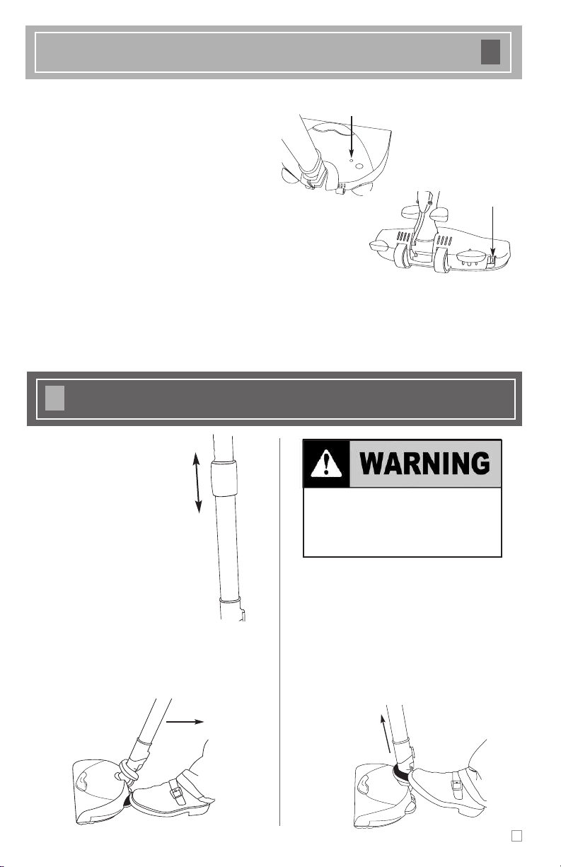
Circuit Breaker Switch
Edge Cleaner
Active brush edge cleaners are on both sides of the
POWERHEAD electric brush. Guide either side of the
brush along baseboards or next to furniture to help
remove dirt trapped at carpet edges.
Overload Protector
The overload protector protects the motor from brush
jamming and belt breakage. If the agitator slows down or
stops, the overload protector shuts off the brush.
To correct problem:
Unplug the electrical cord, remove obstruction. Check brush
area for excessive lint buildup or jamming.
WANDS & ATTACHMENTS
Telescoping Wand
The wand length is adjustable and
requires no assembly. To adjust,
simply pull up or push down on
the wand adjustment collar and
adjust to the desired height.
Warning Lamp
To reset:
Press the reset button on top of the brush. Plug in the
power cord, turn on vacuum and brush.
DO NOT attach or remove handle
or wands while cleaner is ON. This
could cause sparking and damage
the electrical contacts.
Handle Release
Engaging the pedal on the back of
the POWERHEAD marked “handle release”
unlocks the pedal from its
upright position for vacuuming.
Screws
te
Bottom Pla
Wand Attachment
1. For cleaning in those hard-to-reach places such as ceiling or baseboards, the telescopic wand can be disengaged from the neck by depressing the attachment collar as shown and removing the wand. Be sure the
POWERHEAD is unplugged. Reinsert by 'clicking' the
wand back into place when done.
3
Page 4

PILE HEIGHT SETTINGS
XHI
HI
AUTO
MED
LO
X
LO
Belt
Pile Height
ndicator
I
Pile Height Pedal
ELECTRIC BRUSH CARE
Always follow all safety precautions when
cleaning and servicing the POWERHEAD.
Electrical Shock or Personal
Injury Hazard
Disconnect electrical supply before servicing or cleaning the unit. Failure to do so
could result in electrical shock or personal
injury from cleaner suddenly starting.
Belt Changing
Disconnect cleaner from electrical outlet.
Frequently check and remove hair, string and lint
buildup in brush area. If buildup becomes excessive ,
disconnect the brush from wand and follow steps below.
To Remove Belt:
Turn the POWERHEAD
1)
2) Unscrew the two
upside down.
screws which secure
the bottom plate to
ush.
the br
Suggested pile height settings:
To adjust the carpet height setting of the POWERBRUSH, press
the right pedal located on the back of the brush. Each press of
this pedal will adjust the height to the next carpet height position. The current height position can be viewed through the
height indicator window on the top of the unit.
As a general guide:
XLO — low pile carpet
(indoor/outdoor type)
LO — short to medium pile
MED — medium to long pile
3) With the 2 large rear
5) Install the new belt over
Bottom Plate
Screws
6) Secure the agitator assembly into the
7) Line up the cover and baseplate, securing the front
wheels facing you, lift up
the backplate and tilt it
forward from the back
until the front snaps free.
Covering the right side of the
wood agitator is a black protective belt housing, un-clip and remove.
the motor drive and the
other end over of the
agitator assembly as
shown.
back into the base.
first and moving to the back. Replace the screws
holding the backplate and tighten.
AUTO — general pile thickness
HI — thick pile
XHI — very thick pile
4) Life the agitator assembly out and remove
broken or worn belt.
Belt
and bare floors
4
Page 5

MAINTENANCE AND CARE
Top Cover Screw
T
op Cover Screw
Removing the Brushroll
Disconnect brush from electrical outlet.
Your brushroll may need to be removed at times, for
example, to cut out excessive threads or to replace
the belt (see "Replacing the Bulb").
To remove the
brushroll, tur n the
unit over and lift off
the metal bottom
plate by first
unscrewing the two
bottom plate screws
located by the rear
wheels (see diagram).
Pull out the belt
cover guard and pull
the brushroll out.
To reinstall the brushroll,
reinsert the brushroll
back into the unit (make
sure the belt is attached
properly). Next, insert the
belt cover guard. Then,
place the metal bottom
plate back onto the unit
(insert the front end of
the bottom plate first).
Re-insert the two bottom
plate screws and secure.
Replacing the Bulb
Disconnect brush from electrical outlet.
Turn the POWERBRUSH over and
remove the bottom
plate by first unscrewing the two bottom
plate screws located
by the rear wheels.
Locate and remove
the two top cover
screws (see diagram).
Turn the POWERBRUSH
back over, push the
brush flat,
the top cover. Simply
pull the bulb out (no
twisting) and reinsert
factory-authorized bulb.
Place the top cover
back on the unit, turn
the machine over and
re-insert the two top
cover screws. Reinstall
the bottom plate.
and remove
5
Page 6

EXPLOSION PARTS & LIST
6
Page 7

EXPLOSION PARTS & LIST
DI
#ST
AGRAM
1 C350-1000 Top Housing Assembly
2 B350-1515 Headlight Lens
3 C350-7143 Neck Assembly (Fixed)
3 C350-4543B Neck Assembly (Swivel)
4 B350-4714 Teflon Seal
5 B350-7343 Canister Connection Plug
6 B350-7243 Plug Cover
7 B350-7700 Wand Release Axle
8 B350-7600 Wand Release Spring
9 B350-7443B Wand Release Upper Pedal
10 B350-7543B Wand Release Lower Pedal
11 C350-5100 Hidden Raceway Assembly
12 B350-5943 Pedal
13 B350-2601 Tilt Lock Lever
14 B350-2801 Tilt Lock Pin
15 A732-8405 Screws Hi/Lo #8
16 B350-5114 Hidden Raceway
17 C350-9900 Bottom Housing Assembly
18 B350-3400 Tilt Lock Link
19 B350-3500 Tilt Lock Torsion Spring
20 B350-2214 Bottom Housing*
21 B350-8700 Felt Seal for Bottom Housing
22 B350-8600 Felt Seal for Belt Housing
23 B350-3314 Belt Housing*
24 B350-6542B Rear Wheel Assembly
25 B010-0210 Back Wheel Pin 5mm Dia x 38mm
26 C350-1800R Circuit Breaker 2A with wires
27 C350-9700 Height Adjust Assembly
28 C350-4300 LED Assembly
29 B350-5200 Height Adjust Lever
30 B350-0214 Height Adjust Frame
31 B350-5300 Pedal Compression Spring
32 B350-5500 Height Adjust W asher
33 B350-5600 Height Adjust Compression Spring
34 B350-2714 Height Adjust Disk
35 B350-5714 Height Adjust Catch
36 B350-5428 Height Adjust Wheel
37 B350-4200 Axle Stamping
38 C350-9800 Height Adjust Bar Assembly
39 B350-4000 External Retaining Ring 5/16"
40 B350-3942 Axle Height Wheel w/overmold
41 B350-3600 Height Adjust Bar
42 B350-4100 Bottom Plate
43 A430-0205 Screws Pan Head
44 B350-3242 Agitator End Cap w/Overmold
45 C350-3000 Agitator Assembly
46
47
48
49
50
51
52
#DE
OCK
B350-8414 Belt Housing*
A113-2000
B350-2514
A350-0000
A732-8600
B350-6198
A350-0100
B123-0100
SCRIPTION
57mm/Overmolded w/Brass Bushing
B Stack Motor
Belt
Light Bulb
Scr
Reflector
Light Sock
Wir
T 3 1/4 12V
ws #4x1 1/4"
e
et Sna
e Connectors Md.
p In
edge Based
W
* Belt Housing -Before SN 2D0031444 use B350-3314. After use B350-8414.
*Bottom Housing-Before SN2D0031444 use B350-2214.
If after send with B350-8414 & two B350-8600.
7
Page 8

FEATURES
Diagram 1
Handle
Telescopic Wand
Power Brush
Upright Lock Release Pedal
(to clean)
Wand Extension Grip
(to extend wand)
Wand Release Collar
(to remove wand from power brush)
Blockage Warning Light
Height Indicator Window
Height Adjustment Pedal
Diagram 2
Handle
On/Off Control
Wand Release Button
X
enon Headlamp
Soft Furniture Guard
Telescopic Wand
P
ower Brush
Wand Extension Grip
(to extend wand)
Wand Release Collar
(to remove wand from power brush)
F51003
 Loading...