


HR8000
HR8000
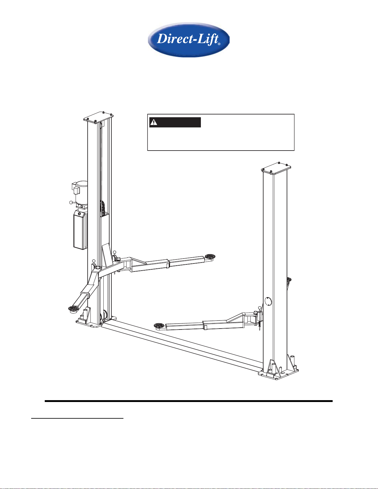
Floor Plate Automotive Lift
8,000 POUND CAPACITY
IMPORTANT
Installation and Service of Automotive Lifts
before installing lift.
Reference ANSI/ALI ALIS,
Safety Requirements for
INSTALLATION / OWNERS MANUALS
Read this manual thoroughly
installation be sure to return documents to package and give all materials to lift owner/operator. When
installation is complete be sure to run lift up and down a few cycles with and without “typical” vehicle
loaded on lift.
TWO COLUMN 8K FLOOR PLATE LIFT CO7589 IN50014 Rev. D 03/2/2010
before installing, operating, or maintaining this lift. When done with
1

TABLE OF CONTENTS
• IMPORTANT INFORMATION.....................................................................2
• GENERAL LIFT INFORMATION / FEATURES.......................................... 2
• LIFT SPECIFICATIONS:............................................................................. 4
• LIFT AREA LAYOUT INFORMATION........................................................ 6
• FOUNDATION and ANCHORING REQUIREMENTS................................7
• TOOLS and EQUIPMENT REQUIRED for INSTALL ................................8
• INSTALLATION PROCEDURE..................................................................9
• OWNER / EMPLOYER RESPONSIBILITIES ............................................. 15
• LIFT LOCKOUT/TAGOUT.......................................................................... 16
• SAFETY PROCEDURES............................................................................ 17
• LIFT OPERATION....................................................................................... 19
• PREVENTIVE MAINTENANCE SCHEDULE .............................................20
• TROUBLESHOOTING................................................................................ 22
• ILLUSTRATED PARTS BREAKDOWN ..................................................... 24
• PARTS LIST................................................................................................28
IMPORTANT INFORMATION
Two Post Lifts
1. Any freight damage must be noted on the freight bill before signing and reported to the freight carrier
with a freight claim established. Identify the components and check for shortages. If shortages are
discovered, please contact the Distributor / Sales Rep. in your area for service.
2. Consult building owner and / or architect’s plans when applicable to establish the best lift location. The
lift should be located on a relatively level floor with 4 in. minimum thickness, 3000-psi concrete slab
that has been properly cured. There can be no cracks in the slab within 36 in. of the base plate
location, and no seams in the foundation within 6 in. of its location! Remember: any structure
is only as strong as the foundation on which it is located!
IMPORTANT! Make sure you have extra help or heavy duty lifting equipment when
unloading and assembling the lift.
3. Please read the safety procedures and operating instructions in this manual before operating lift. Keep
this manual near lift at all times. Make sure all operators read this manual.
4. The lift should be located on a relatively level floor of less than 3 degrees slope. If slope is
questionable, consider a survey of the site and/or the possibility of pouring a new level concrete slab.
5. Make sure you have enough area and ceiling height to install lift. (See Lift Specifications)
6. Never raise a car until you have double checked all bolts, nuts and hose fittings.
7. Always lower the lift onto the locks before going under the vehicle. Never allow anyone to go under
the lift when raising or lowering.
This is a vehicle lift installation/operation manual and no attempt is made or implied herein to
instruct the user in lifting methods particular to an individual application. Rather, the contents of
this manual are intended as a basis for operation and maintenance of the unit as it stands alone
or as it is intended and anticipated to be used in conjunction with other equipment.
Proper application of the equipment described herein is limited to the parameters detailed in the
specifications and the uses set forth in the descriptive passages. Any other proposed
application of this equipment should be documented and submitted in writing to the factory for
examination. The user assumes full responsibility for any equipment damage, personal injury, or
alteration of the equipment described in this manual or any subsequent damages.
TWO COLUMN 8K FLOOR PLATE LIFT CO7589 IN50014 Rev. D 03/2/2010
2

CAUTION!!
ENSURE THAT ALL CABLE SHEAVES, BEARINGS, AND SHAFTS ARE SUFFICIENTLY
LUBRICATED. ALSO, THE CORNERS OF EACH COLUMN SHOULD BE LIGHTLY
GREASED WITH QUALITY TYPE LITHIUM GREASE PRIOR TO OPERATING THE LIFT.
LUBRICATE ALL ON AN ANNUAL BASIS.
Motors and all electrical components are not sealed against the weather and moisture.
Install this lift in a protected indoor location. Failure by the owner to provide the
recommended shelter could result in unsatisfactory lift performance, property damage,
or personal injury.
GENERAL LIFT INFORMATION and FEATURES
FLOOR PLATE MODEL
The following lift is a 2-Column Hydraulic, leaf chain driven unit.
The name/model numbers are designated below:
• Floor Plate (HR8000): 2-Column Lift, Floor Plate Lift type, 8000 lbs. Capacity, Symmetric
Swing Arm set up.
This lift is an 8,000 lb. capacity, 2-Post Lifts. The locking latch system is very similar to
an extension ladder. The locking latch is in contact with the latch rack. As the lift rises
the locking latch drops into place. The locking latch engages in latch rack in 3”
increments starting at about 16” from the ground. The locking latches must be manually
disengaged for the lift to lower. The locking latch is released by pulling the Release Cable
raising the latch up off the latch rack. Once the raise button is pressed, the latch will
automatically reengage after approximately 3" of travel. Heavy bearings and heavy-duty
leaf chains are used throughout the lift. The work is done with the heavy-duty chain
connected to a 2-1/2" cylinder, driven by an electric / hydraulic pump.
TWO COLUMN 8K FLOOR PLATE LIFT CO7589 IN50014 Rev. D 03/2/2010
3

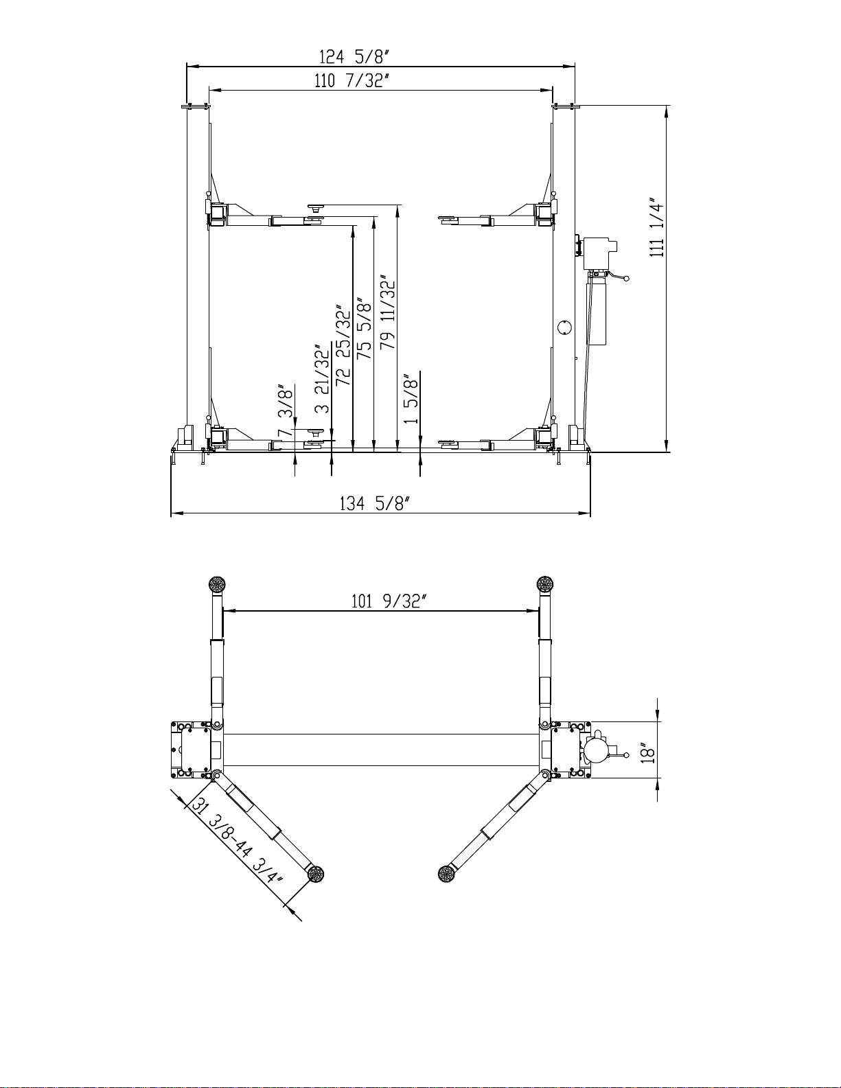
LIFT SPECIFICATIONS
FLOOR PLATE
MODEL
Capacity 8,000 lbs. (2,000 lbs per Arm)
Rise Time 60 Seconds
Overall Height 111.26”
Overall Floor Width 134.63”
Maximum Lift Height 79”
Minimum Pad Height 3-5/8”
Between Columns 111”
Column Size 7” x 11”
Drive Thru 101.54”
Base Plate Width 11”
Motor 2HP, 208 - 230 VAC, 1PH
TWO COLUMN 8K FLOOR PLATE LIFT CO7589 IN50014 Rev. D 03/2/2010
4
TWO COLUMN 8K FLOOR PLATE LIFT CO7589 IN50014 Rev. D 03/2/2010
5
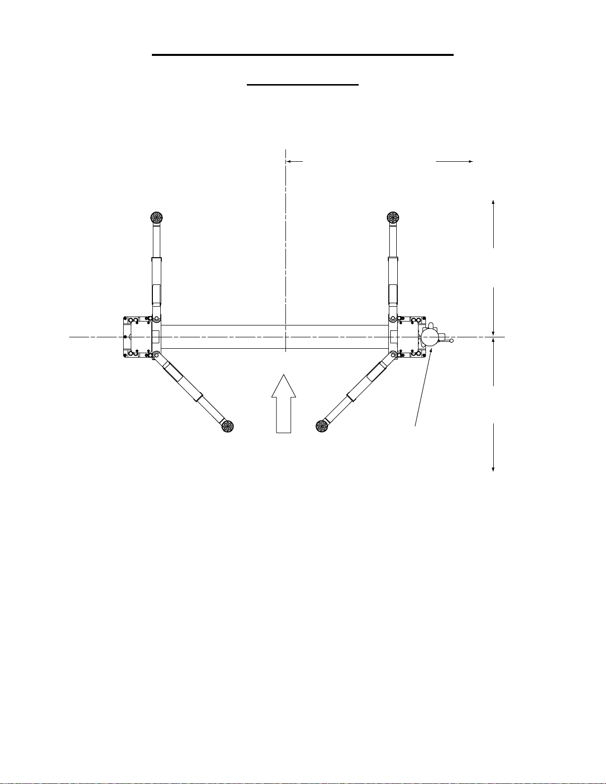
LIFT AREA LAYOUT INFORMATION
FLOOR PLATE
MODEL
(Symmetrical Arm configuration)
6' 0" (1829mm) minimum to
nearest obstruction or bay.
7' 0" (2134mm) minimum to
nearest wall.
minimum to nearest
11' 0" (3353mm)
obstruction
13' 0" (3963mm)
minimum to nearest
obstruction
APPROACH
Power Unit
NOTE: Lift can be installed so power unit can column can be located on
either side. However to save operation steps it is recommended that it is
placed on passenger side of lift.
TWO COLUMN 8K FLOOR PLATE LIFT CO7589 IN50014 Rev. D 03/2/2010
6
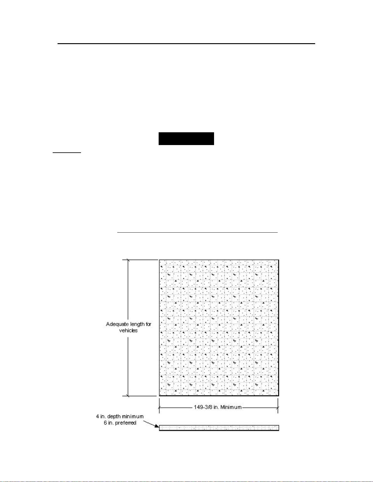
FOUNDATION and ANCHORING REQUIREMENTS
1. Concrete shall have compression strength of at least 3,000 PSI and a minimum thickness
of 4” in order to achieve a minimum anchor embedment of 3 1/4”. NOTE: When using the
standard supplied 3/4” x 5 1/2 long anchors; if the top of the anchor exceeds 2 1/4” above
the floor grade, you DO NOT have enough embedment.
2. Maintain a 6” minimum distance from any slab edge or seam. Hole to hole spacing
should be a minimum 61/2” in any direction. Hole depth should be a minimum of 4”.
CAUTION!!
3. DO NOT install on asphalt or other similar unstable surface. Columns are supported only
by anchoring to floor.
4. Using the horseshoe shims provided, shim each column base as required until each
column is plumb. If one column has to be elevated to match the plane of the other column,
full size base shim plates should be used. Torque anchors to 85 ft-lbs. Shim thickness
MUST NOT exceed ½” when using the 5 1/2” long anchors provided with the lift. Adjust
the column extensions plumb.
5. If anchors do not tighten to 85 ft-lbs. installation torque, replace the concrete under each
column base with a 4’ x 4’ x 6” thick 3,000 PSI minimum concrete pad keyed under and
flush with the top of existing floor. Allow concrete to cure before installing lifts and
anchors (typically 2 to 3 weeks).
TWO COLUMN 8K FLOOR PLATE LIFT CO7589 IN50014 Rev. D 03/2/2010
7

TOOLS & EQUIPMENT REQUIRED FOR INSTALL
The installation of this lift is relatively simple and can be accomplished by two men in a
few hours. The following tools and equipment are needed:
• Hoist or Forklift (optional)
• Two 10’ to 12’ step ladders
• ISO 32 Light Hydraulic Oil (approx. 12 quarts)
• Tape Measure
• Rotary Hammer Drill with 3/4 in. Drill Bit (Core Drill Rebar Cutter recommended)
• 4’ Level
• Metric Sockets and Open Wrench set
• Vise grips
• 8mm Socket Head Wrench
• Torque wrench with 1-1/8" socket for anchors
• Teflon Tape
TWO COLUMN 8K FLOOR PLATE LIFT CO7589 IN50014 Rev. D 03/2/2010
8
r
INSTALLATION PROCEDURE
STEP 1: After unloading the lift, place it near the intended installation location.
STEP 2: Remove the shipping bands and packing materials from the unit. The Power Unit will
be unpacked from the top. Note:
STEP 3: Remove the packing brackets and bolts holding the two columns together (do not
discard bolts; they are used in the assembly of the lift).
STEP 4: Once the power unit column location is decided, insure that the proper lift placement is
observed from walls and obstacles. Also check the ceiling height for clearance in this location.
Note:
the power side with the passenger side of the vehicle when loaded on the lift to save
steps during operation.
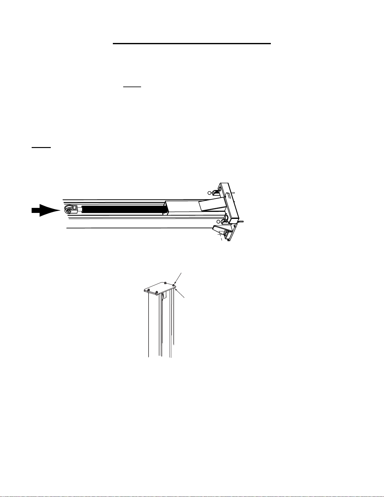
STEP 5: Install the cylinders into the carriage.
the power unit column can be located on either side. It is helpful to try and locate
Be careful not to drop power unit.
STEP 6: Install the top plate onto the top of the columns.
M12 x 1-9/16”Bolt
& Washer
Lockwashe
& M12Nut
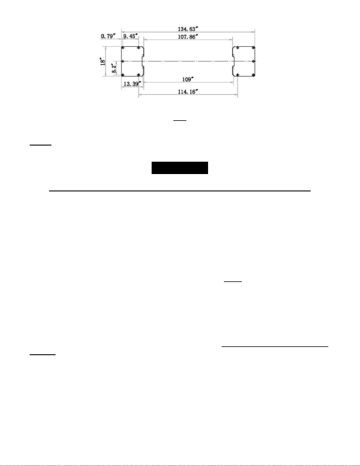
STEP 7: Position the columns facing each other 134-5/8” outside base plates. Square the
columns by measuring diagonally from corner points on base plates (within 1/4”).
TWO COLUMN 8K FLOOR PLATE LIFT CO7589 IN50014 Rev. D 03/2/2010
9
STEP 8: Use the existing holes in column base plate as a guide for drilling the 3/4” diameter
holes into the concrete. Drill the anchor holes only for ONE column, installing anchors as you go.
You will install anchors in second column after the cables, hoses, and floorplate are installed.
NOTE: Drilling thru concrete slab (recommended) will allow the anchor to be driven thru the
bottom of slab, if the threads are damaged or if the lift will need to be relocated.
CAUTION!!
Anchors must be at least 6” from the edge of the slab or any seam.
1. Use a concrete hammer drill with a carbide tip, solid drill bit the same diameter as
the anchor, 3/4”. (.775 to .787 inches diameter). Do not use excessively worn bits or
bits which have been incorrectly sharpened.
2. Keep the drill in a perpendicular line while drilling.
3. Let the drill do the work. Do not apply excessive pressure. Lift the drill up and down
occasionally to remove residue to reduce binding.
4. Drill the hole to depth equal to the length of anchor. Note: Drilling thru concrete
(recommended) will allow the anchor to be driven thru the bottom of foundation if
the threads are damaged or if the lift will need to be relocated.
5. For better holding power blow dust from the hole.
Place a flat washer and hex nut over threaded end of anchor, leaving approximately 1/2"
of thread exposed carefully tap anchor. Do not damage threads. Tap anchor into the
concrete until nut and flat washer are against base plate. Do not use an impact wrench to
tighten! Tighten the nut, two or three turns on average concrete (28-day cure). If the
concrete is very hard only one or two turns may be required. Check each anchor bolt
with torque wrench set to 85 foot pounds.
TWO COLUMN 8K FLOOR PLATE LIFT CO7589 IN50014 Rev. D 03/2/2010
10
 Loading...