

Direct Lift Drop Tail Motorcycle Lift User Manual
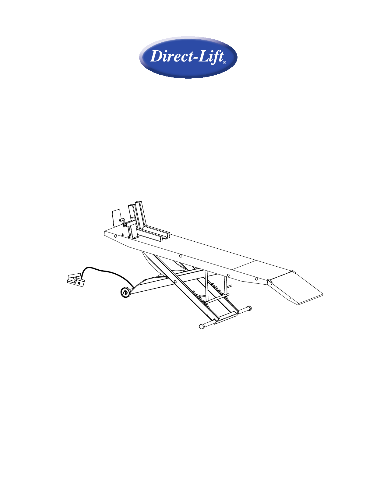
Drop Tail Motorcycle Lift
1,000 lbs. capacity
Installation, Safety, Operation, Maintenance
Entire contents © 2011 by Vehicle Service Group. All rights reserved. IN50012
CO7932 Rev. C 04/20/2011

Inspection upon receipt of the lift
1. Always inspect the lift for freight damage and make note of any damage on the bill of lading.
2. In case of freight damage, call the truck line immediately and report the damage as a freight claim.
Final Set-Up
This lift is more than 90% factory pre-assembled. The following steps will guide you through the nal
set-up. The packaged lift weighs approximately 700 lbs. While disassembling the sub components
will weigh less than that, two or more people will be needed to unload and move the lift around during
initial installation/unpacking of the lift.
1. Unpack the lift from the shipping skid. With the lift table up side down, connect the air hose to the
air cylinder.
2. After tightening the hose to the cylinder, ip the lift over with the table surface up.
3. Connect the other end of the air hose to the foot-operated valve. Put a small amount of air tool oil
in the inlet side of the valve. Then connect the foot-operated valve to 100 PSI air supply. DO NOT
USE AIR SUPPLY WITH PRESSURE MORE THAN 100 PSI.
4. Release the safety bar by pushing the handle down. Operate the foot valve by stepping on the
footpad forward to raise the lift. The safety bar should engage the ladder automatically while lift is
rising.
5. Step on the footpad again to set the pad in middle position to stop the lift when it reaches
the desired height. ALWAYS LOWER LIFT IN THE NEAREST LOCKED POSITION BEFORE
BEGINNING WORK. NEVER USE THE LIFT UNLESS YOU ARE IN A LOCKED POSITION.
6. Lubricating the joints again before use will ensure a better performance of the lift. While the lift is
fully raised, lubricate the top of the cylinder with oil.
7. Vice Installation, see Fig. 1:
a. Install the vise clamp using (4) M8 x 20 bolts, lockwashers, and nuts.
b. Install the moveable vise arm into the vise clamp.
c. Install the xed vise arm using (6) M8 x 20 bolts, lockwashers, and nuts.
8. Install wheel stop as shown, Fig. 1 using M8 x 20 bolts, lockwashers, and nuts.
9. Install tie down eyebolts as shown in Fig. 1 using M10 eyebolts, washers, and nuts.
10. Install the drop tail portion of the lift. Use 2 supplied detent pins to lock into place.
11. Install the approach ramp by dropping it into the holes punched on the rear edge of the table.
XLT Installation (THIS KIT IS OPTIONAL)
1. Run the Extension panel tubes through the holes on the side of the table. Install the side
extensions onto the protruding tubes, Fig. 2. Use locking pins to secure the tubes, Fig. 3.
2. Drop the ramps for the side extensions in place as shown, Fig. 3. Attach using M6 x 16 bolts,
lockwashers, and nuts, Fig. 3.
2
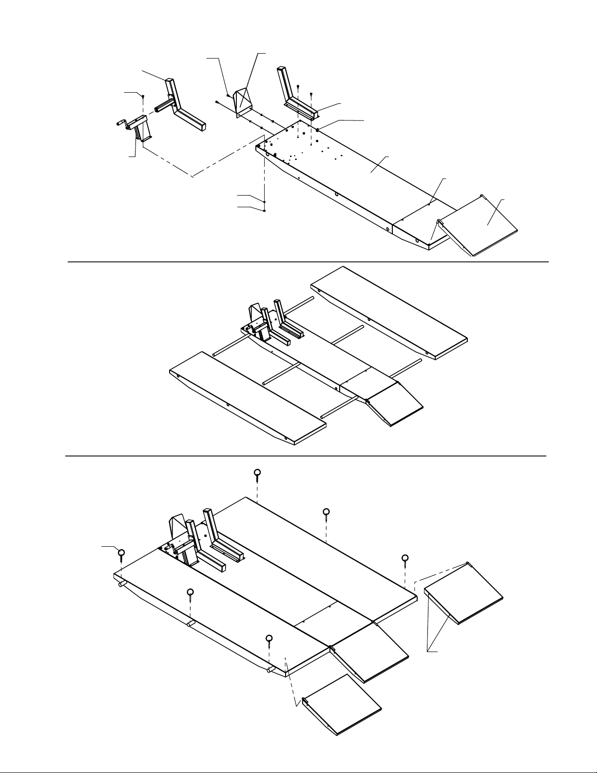
Moveable Vise Arm
M8 x 20 Bolt
M8 x 20 Bolt,
Ø10 Lockwasher,
M8 Nut
Front Wheel Stop
Fixed Vise Arm
Tie Down Eye Bolt
Ø10 Washer
M10 Nut
Vise Clamp
Ø10 Lockwasher
M8 Nut
Fig. 1
NOTE: XLT KIT IS OPTIONAL
Fig. 2
Top of Platform
Detent Pins
Approach Ramp
Lock Pins
NOTE: XLT KIT IS OPTIONAL
Bolt Ramps Together Using
(2) M6 x 16 Bolt, Lockwasher,
and M6 Nut (Both Sides)
Fig. 3
3

The Owner/Employer:
• Shall ensure that lift operators are qualied and that they are trained in
the safe use and operation of the lift using the manufacturer’s operating
instructions; ALI/SM01-1, ALI Lifting it Right safety manual; ALI/ST-90
ALI Safety Tips card; ANSI/ALI ALOIM-2000, American National Standard
for Automotive Lifts-Safety Requirements for Operation, Inspection and
Maintenance; ALI/WL Series, ALI Uniform Warning Label Decals/Placards;
and in the case of frame engaging lifts, ALI/LP-GUIDE, Vehicle Lifting Points/
Quick Reference Guide for Frame Engaging Lifts.
• Shall establish procedures to periodically inspect the lift in accordance with
the lift manufacturer’s instructions or ANSI/ALI ALOIM-2000, American
National Standard for Automotive Lifts-Safety Requirements for Operation,
Inspection and Maintenance; and The Employer Shall ensure that lift
inspectors are qualied and that they are adequately trained in the inspection
of the lift.
• Shall establish procedures to periodically maintain the lift in accordance
with the lift manufacturer’s instructions or ANSI/ALI ALOIM-2000, American
National Standard for Automotive Lifts-Safety Requirements for Operation,
Inspection and Maintenance; and The Employer Shall ensure that lift
maintenance personnel are qualied and that they are adequately trained in
the maintenance of the lift.
• Shall maintain the periodic inspection and maintenance records
recommended by the manufacturer or ANSI/ALI ALOIM-2000, American
National Standard for Automotive Lifts-Safety Requirements for Operation,
Inspection and Maintenance.
• Shall display the lift manufacturer’s operating instructions; ALI/SM 93-1,
ALI Lifting it Right safety manual; ALI/ST-90 ALI Safety Tips card; ANSI/
ALI ALOIM-2000, American National Standard for Automotive Lifts-Safety
Requirements for Operation, Inspection and Maintenance; and in the case of
frame engaging lifts, ALI/LP-GUIDE, Vehicle Lifting Points/Quick Reference
Guide for Frame Engaging Lifts; in a conspicuous location in the lift area
convenient to the operator.
• Shall provide necessary lockout/tagout means for energy sources per ANSI
Z244.1-1982 (R1993), Safety Requirements for the Lockout/Tagout of Energy
Sources, before beginning any lift repairs.
• Shall not modify the lift in any manner without the prior written consent of the
manufacturer.
4
 Loading...