

Page 1
OWNER’S GUIDE
INSTALLATION GUIDE
Headrest Monitor Bucket
MODEL HRB100
Page 2

Page 3

Table of Contents
Limited Three-Year Warranty . . . . . . . . . . . . . . . . . . . . . . . . . . . . . . . . . . . . .4
Safety Instructions . . . . . . . . . . . . . . . . . . . . . . . . . . . . . . . . . . . . . . . . . . . .5
Important Safeguards . . . . . . . . . . . . . . . . . . . . . . . . . . . . . . . . . . . . . . . . . .5
When Cleaning the Vehicle ...........................................................................................................5
While Driving.............................................................................................................................5
Repairs .....................................................................................................................................5
Important Information . . . . . . . . . . . . . . . . . . . . . . . . . . . . . . . . . . . . . . . . . .6
FCC Notice.................................................................................................................................6
Your Warranty ............................................................................................................................6
Features . . . . . . . . . . . . . . . . . . . . . . . . . . . . . . . . . . . . . . . . . . . . . . . . . . . .6
Features....................................................................................................................................6
Accessories................................................................................................................................6
Basic Operation . . . . . . . . . . . . . . . . . . . . . . . . . . . . . . . . . . . . . . . . . . . . . . .7
Description................................................................................................................................7
Viewing Angle............................................................................................................................7
Maintenance .............................................................................................................................7
Installation . . . . . . . . . . . . . . . . . . . . . . . . . . . . . . . . . . . . . . . . . . . . . . . . . .8
Installation with Removable Headrest Cover ...................................................................................9
Installing the Monitor.................................................................................................................9
Removing the Monitor.................................................................................................................9
© 2003 Directed Electronics, Inc.
3
Page 4

Limited Three-Year Warranty
For a period of THREE YEARS from the date of purchase,
Directed Electronics, Inc. ("DIRECTED") promises to the
original purchaser to repair or replace, free of cost, with a
comparable reconditioned model any HEADREST BUCKET
(hereafter the "UNIT"), which proves to be defective in
workmanship or material defect under normal and reason-
able use during the first 3 years after the purchase and
installation of the unit provided the following conditions
are met: the unit was purchased and installed by an author-
ized DIRECTED dealer; the unit remains in the vehicle in
which the unit was originally installed; and the unit is
returned to DIRECTED. The unit in question must be
returned to DIRECTED postage paid and must be accompa-
nied by a clear, legible copy of the bill of sale bearing the
following information:
■
Date of Purchase
■
Your Full name and address
■
Authorized dealer's company name and address
■
Type of unit installed
■
Year, make and model of the automobile
■
Automobile license number
■
Vehicle Identification number
■
Installation receipts
All components and accessories other that the unit, includ-
ing without limitation the remote control, cables and
installation accessories carry a 60-day warranty from the
date of purchase of the same.
This warranty is automatically void if the unit is bought
from anyone other than an authorized dealer, the unit's
date code or serial number is defaced, missing or altered;
the unit has been modified or used in a manner contrary to
its intended purpose; or the unit has been damaged by
accident, unreasonable use, neglect, improper service,
installation or other causes not arising out of defects in
workmanship, materials or construction. This warranty is
nontransferable and does not cover batteries. This warran-
ty does not co
ver labor costs for the removal, diagnosis,
troubleshooting or reinstallation of the unit. For service on
an out-of-warranty product a flat fate fee by model is
charged. Contact your authorized dealer to obtain the serv-
ice charge for your unit.
TO THE MAXIMUM EXTENT ALLOWED BY LAW, ALL WAR-
RANTIES, INCLUDING BUT NOT LIMITED TO EXPRESS WAR-
RANTY, IMPLIED WARRANTY, WARRANTY OF MER-
CHANTABILITY, FITNESS FOR PARTICULAR PURPOSE AND
WARRANTY OF NON-INFRINGEMENT OF INTELLECTUAL
PROPERTY, ARE EXPRESSLY EXCLUDED; AND DIRECTED
NEITHER ASSUMES NOR AUTHORIZES ANY PERSON OR
ENTITY TO ASSUME FOR IT ANY DUTY, OBLIGATION OR
LIABILITY IN CONNECTION WITH ITS PRODUCTS. DIRECT-
ED DISCLAIMS AND HAS ABSOLUTELY NO LIABILITY FOR
ANY AND ALL ACTS OF THIRD PARTIES INCLUDING DEAL-
ERS OR INSTALLERS. IN THE EVENT OF A CLAIM OR A DIS-
PUTE INVOLVING DIRECTED OR ITS SUBSIDIARY, THE
PROPER VENUE SHALL BE SAN DIEGO COUNTY IN THE
STATE OF CALIFORNIA. CALIFORNIA STATE LAWS AND
APPLICABLE FEDERAL LAWS SHALL APPLY AND GOVERN
THE DISPUTE. THE MAXIMUM RECOVERY UNDER ANY
CLAIM AGAINST DIRECTED SHALL BE STRICTLY LIMITED
TO THE AUTHORIZED DIRECTED DEALER'S PURCHASE
PRICE OF THE UNIT. DIRECTED SHALL NOT BE RESPONSI-
BLE FOR ANY DAMAGES WHATSOEVER, INCLUDING BUT
NOT LIMITED TO, ANY CONSEQUENTIAL DAMAGES, INCI-
DENTAL DAMAGES, DAMAGES FOR THE LOSS OF TIME,
LOSS OF EARNINGS, COMMERCIAL LOSS, LOSS OF ECO-
NOMIC OPPORTUNITY AND THE LIKE. NOTWITHSTANDING
THE ABOVE, THE MANUFACTURER DOES OFFER A LIMITED
WARRANTY TO REPLACE OR REPAIR THE CONTROL MOD-
ULE AS DESCRIBED ABOVE. Some states do not allow lim-
itations on how long an implied warranty will last or the
exclusion or limitation of incidental or consequential dam-
ages. This warranty gives you specific legal rights and you
may also have other rights that vary from State to State.
DIRECTED does not and has not authorized any person or
entity to create for it any other obligation, promise, duty
or obligation in connection with this UNIT.
4
© 2003 Directed Electronics, Inc.
Page 5

Safety Instructions
WARNING: TO REDUCE THE RISK OF FIRE OR ELECTRIC SHOCK, DO NOT EXPOSE THIS EQUIPMENT TO
■
Only operate the unit as described in this
guide. Attempts to use or modify this unit
contrary to the descriptions in this guide
may cause damage and void the warranty.
■
This unit is designed for use in vehicles
with standard (-) 12 volt ground electrical
systems.
RAIN OR MOISTURE. TO REDUCE THE RISK OF FIRE OR ELECTRIC SHOCK AND ANNOYING
INTERFERENCE, USE ONLY THE INCLUDED HARDWARE.
THIS UNIT IS ONLY DESIGNED FOR REAR SEAT PASSENGER VIEWING AND IS NOT INTENDED
FOR VIEWING BY THE DRIVER WHILE THE VEHICLE IS IN MOTION. SUCH USE MAY DISTRACT
THE DRIVER OR INTERFERE WITH THE SAFE OPERATION OF THE VEHICLE, AND MAY ALSO
VIOLATE STATE LAW.
DIRECTED ELECTRONICS, INC. DISCLAIMS ANY LIABILITY FOR ANY BODILY INJURY,
INCLUDING FATALITIES, OR PROPERTY DAMAGE THAT MAY RESULT FROM ANY IMPROPER OR
UNINTENDED USES OF THIS PRODUCT.
■
Exposure to moisture or dust can cause
harmful damage to the internal electronics. Do not mount near cup holders or in
areas where spills may occur.
Important Safeguards
WHEN CLEANING THE VEHICLE
REPAIRS
Do not spray this unit with water or cleaning
solutions. Moisture and the chemicals found in
cleaning fluids could damage the unit’s finish
and interior electronics.
WHILE DRIVING
This unit is intended for use in the rear seat area
only, and should not be installed in a location that
would allow the driver to view it while driving.
© 2003 Directed Electronics, Inc.
If the unit stops working for any reason, dis-
continue use immediately and consult with your
retailer about any necessary repairs.
5
Page 6

Important Information
FCC NOTICE
This device complies with Part 15 of FCC rules.
Operation is subject to the following two condi-
tions: (1) This device may not cause harmful
interference, and (2) this device must accept
any interference received, including interfer-
ence that may cause undesired operation.
Changes or modifications not expressly
approved by the party responsible for compli-
ance could void the user's authority to operate
this device.
Features
FEATURES
■
Adjustable tilt
■
Contoured design for GM vehicles plus universal fit for many other vehicles.
■
RVM Technology
■
Easy installation
YOUR WARRANTY
Your warranty registration must be completely
filled out and returned within 10 days of pur-
chase. Your product warranty will not be vali-
dated if your warranty registration is not
returned. Make sure you receive the warranty
registration from your dealer. It is also neces-
sary to keep your proof of purchase, which
reflects that the product was installed by an au-
thorized dealer.
ACCESSORIES
■
Trim bezel.
■
Receiver bracket
■
Hot foot connector
■
Screws and other mounting hardware.
NOTE: This product requires specialized tools and instal-
lation techniques; Directed recommends that this
unit be installed by a retailer that employs MECP
(Mobile Electronics Certification Program)
installers. Contact your retailer for details.
NOTE: This manual makes reference to optional Directed
Video parts not included with this product.
6
© 2003 Directed Electronics, Inc.
Page 7

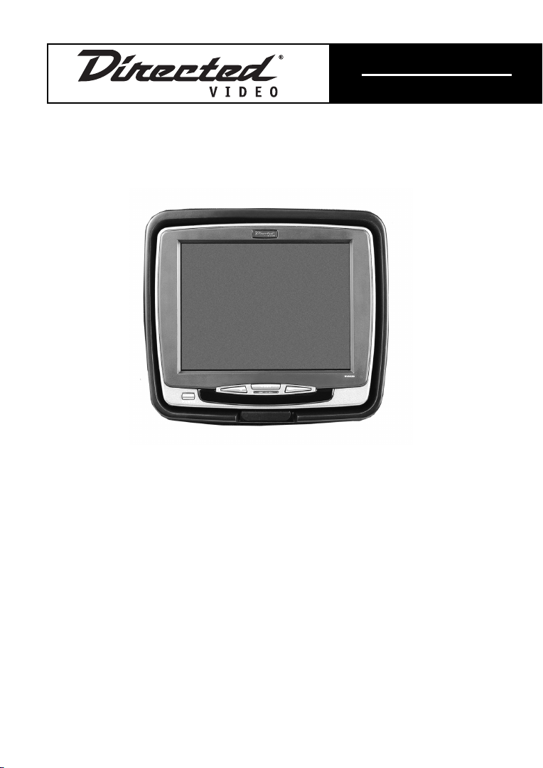
Basic Operation
1
2
3
4
5
6
DESCRIPTION
1. Monitor bucket
2. Receiver bracket
3. Release tab
4. Hinge
5. Hot foot connector
6. Mounting feet
VIEWING ANGLE
The picture viewing angle can be easily adjust-
ed by pulling on the release tab.
© 2003 Directed Electronics, Inc.
MAINTENANCE
Keep the unit clean and free of dust and mois-
ture and it will provide years of trouble-free
operation. Do not allow any cleaning fluids on
the bracket or bezel; they may contain chemi-
cals that can harm the finish.
To clean the unit, simply use a soft, dry cloth
and gently wipe away any dirt.
7
Page 8

Installation
The HRB100 mounting adapter allows secure
installation of the Directed Video RVM Series
Removable Monitors by installing the mounting
assembly into the vehicle headrest or seatbacks.
The HRB100 will accommodate the Directed Video
5.6”, 6.8”, and 7.0” monitors.
The HRB100 consists of two major pieces: the
receiver bracket and the headrest bucket.
1. Using the supplied template, center the
cut out area on the headrest or seatback
and mark the fabric area to be cut as indicated. With a new razor knife, cut the fabric as marked. Then cut the foam as indicated on the template. Using the knife
remove as much of the foam padding as
necessary to allow clearance of the monitor bucket.
WARNING! Be careful not to remove the headrest fab
ric past the line marked FABRIC CUT LINE.
If the fabric is removed past this line, the
headrest’s inner foam may be visible after
the completed installation.
2. Once the headrest has been marked and
cut to accommodate the monitor bucket
the metal support bar around the inside of
the headrest will be noticeable. The monitor bucket will be secured to this bar.
3. Run the supplied din cable through the
bottom of the headrest. Leave enough
slack in the cable so the headrest still has
full movement during adjustment.
4. Secure the headrest bucket by tying the
supplied zip ties through the mounting
feet and around the metal support bars.
5. The RVM Monitor locks into the receiver
bracket until physically released. The
release mechanism is in the rear of the
bracket.
8
© 2003 Directed Electronics, Inc.
Page 9

INSTALLATION WITH
REMOVABLE HEADREST COVER
1. Remove the headrest cover to determine if
it has room in it for the monitor without
structurally weakening it.
2. With the cover still removed, position the
cutout template against the rear of the
headrest and mark the area to be cut out.
3. Remove the material to a depth sufficient
for the lip of the mounting bezel to fit
flush against the rear of the headrest once
installed.
4. Cut an access hole for the cable to exit
next to the headrest adjustment bar.
5. Reinstall the headrest cover. Trim it 1”
smaller than the size of the mounting bucket hole. When trimming, it is best to leave
extra material that can be glued into the
hole before installing the mounting bucket.
6. Route the cable through the headrest
access hole and the rear opening of the
mounting bucket.
7. Install the bucket. Some headrests have
material that is strong enough to screw
the bucket into. Others will require quality
adhesive for mounting or tie straps to
secure it to the metal support bars.
8. Route the cable through the seat cover
and reinstall the headrest. Leave enough
slack in the cable so the headrest still has
full movement during adjustment.
9. Complete the cable routing to the video
source.
INSTALLING THE MONITOR
Place the monitor directly in front of the buck-
et and line up the hot foot connector on the
bracket. Place your thumb on the top and press
firmly until it locks into place. Then place your
thumb on the bottom of the monitor and press
firmly until it locks into place also.
REMOVING THE MONITOR
Pull gently on the lower bracket tab and lift the
monitor to the maximum angle. Reach under the
bracket and pull down on the release tab. With the
monitor released, lift it off the mounting bracket.
Release Tab
© 2003 Directed Electronics, Inc.
9
Page 10

10
© 2003 Directed Electronics, Inc.
Page 11

© 2003 Directed Electronics, Inc.
11
Page 12

The company behind this system is Directed Electronics, Inc.
Since its inception, Directed has had one purpose, to provide consumers with the finest vehicle security, car stereo
products, rear seat entertainment, and accessories available. The recipient of more than 20 patents in the field of
advanced electronic technology, Directed is ISO 9001 registered.
Quality Directed Electronics products are sold and serviced throughout North America and around the world.
Call (800) 274-0200 for more information about our products and services.
Directed®is committed to delivering world-class quality products
and services that excite and delight our customers.
12
Directed Electronics, Inc.
Vista, CA 92083
www.directed.com
© 2003 Directed Electronics, Inc. - All rights reserved
N87301 1-03
© 2003 Directed Electronics, Inc.
 Loading...