


350HV
Installation Guide
NOTE: This product is intended for installation by a professional installer only! Any attempt to install this product by any person other than a trained professional may result in severe damage to a vehicle’s electrical system and components.
© 2005 Directed Electronics, Inc. Vista, CA
N426V 07-05

The Bitwriter® (p/n 998T) requires chip version 1.4 or newer to program this unit.
Bitwriter™, Code Hopping™, , Doubleguard®, ESP™, FailSafe®, Ghost Switch™, Learn Routine™, Nite-Lite®, Nuisance Prevention® Circuitry, NPC®, Revenger®, Silent Mode™, Soft Chirp®, Stinger®, Valet®, Vehicle Recovery System®, VRS®, and Warn Away® are all Trademarks or Registered Trademarks of Directed Electronics, Inc.
www.directechs.com
DirectFax 800-999-1329 Technical Support 800-753-0800
These resources are for authorized Directed Dealer use only.

Table of Contents |
|
Primary Harness (H1) Wire Connection Guide............................................................................ |
4 |
Primary Harness Wiring Diagram............................................................................................. |
4 |
Primary Harness Wiring Instructions........................................................................................ |
4 |
Door Lock Harness (H2), 3-PIN Connector ................................................................................ |
9 |
Peripheral Plug-In Harnesses....................................................................................................... |
10 |
Super Bright LED, 2-Pin WHITE Plug.................................................................................. |
10 |
Valet/Program Switch, 2-Pin BLUE Plug ................................................................................ |
10 |
Programmer Interface, 3-Pin BLACK Plug ............................................................................. |
11 |
Mounting the Receiver/Antenna ............................................................................................. |
11 |
On-Board Dual-Stage Shock Sensor ........................................................................................... |
12 |
Optional Sensor Harness, 4-pin Connector ................................................................................ |
12 |
Programming Jumper ................................................................................................................. |
13 |
Light Flash Jumper.................................................................................................................. |
13 |
Bypassing Sensor Inputs.............................................................................................................. |
13 |
System Features Learn Routine ................................................................................................... |
14 |
System Features Menus............................................................................................................... |
16 |
Menu #1 - Basic Features........................................................................................................ |
17 |
Menu #2 - Advanced Features................................................................................................. |
17 |
Feature Descriptions ................................................................................................................... |
17 |
Menu #1 - Basic Features........................................................................................................ |
18 |
Transmitter/Receiver Learn Routine ........................................................................................... |
21 |
Transmitter Configurations......................................................................................................... |
23 |
Standard Configuration........................................................................................................... |
23 |
Expanded Configuration ........................................................................................................ |
23 |
Diagnostics ................................................................................................................................. |
24 |
Arm/Disarm Diagnostics......................................................................................................... |
24 |
System Status Chirps............................................................................................................... |
24 |
Table of Zones ........................................................................................................................ |
25 |
Long Term Event History........................................................................................................... |
25 |
Multi-Level Security Arming....................................................................................................... |
26 |
Multi-Level Security arming allows the operator to select which inputs and sensors are active during |
|
a particular arming cycle. For a full description of Multi-Level Security Arming operation for testing |
|
purposes refer to the owner's manual. ......................................................................................... |
26 |
Optional Vehicle Recovery System (VRS)................................................................................... |
26 |
Nuisance Prevention® Circuitry .................................................................................................. |
26 |
Rapid Resume Logic ................................................................................................................... |
27 |
Troubleshooting.......................................................................................................................... |
27 |
Wiring Quick Reference Guide................................................................................................... |
29 |
© 2005 Directed Electronics, Inc. all rights reserved |
3 |

Primary Harness (H1)Wire Connection Guide
Primary Harness Wiring Diagram
|
___ |
|
|
H1/1 |
ORANGE |
(-) 500 mA Armed Output |
|
|
___ |
|
|
|
|
|
|
H1/2 |
WHITE |
(+)/(-) Selectable Light Flash Output |
|
|
___ |
|
|
|
|
|
|
H1/3 |
WHITE/BLUE |
(-) 200 mA Channel 3 Programmable Output |
|
|
___ |
|
|
|
|
|
|
H1/4 |
BLACK/WHITE |
(-) 200 mA Domelight Supervision Output |
|
|
___ |
|
|
|
|
|
|
H1/5 |
GREEN |
(-) Door Trigger Input, Zone 3 |
|
|
___ |
|
|
|
|
|
|
H1/6 |
BLUE |
(-) Instant Trigger Input, Zone 1 |
|
|
___ |
|
|
|
|
|
|
H1/7 |
VIOLET |
(+) Door Trigger Input, Zone 3 |
|
|
___ |
|
|
|
|
|
|
H1/8 |
BLACK |
(-) Chassis Ground Input |
|
|
___ |
|
|
|
|
|
|
H1/9 |
YELLOW |
(+) Switched Ignition Input, Zone 5 |
|
H1/10 |
___ |
|
|
|
|
||
BROWN |
(+) Siren Output |
||
H1/11 |
___ |
|
|
|
|
||
RED |
(+) Constant Power Input |
||
H1/12 |
___ |
|
|
|
|
||
RED/WHITE |
(-) 200 mA Channel 2 Output |
||
|
|
|
|
|
|
|
|
Primary Harness Wiring Instructions
This guide describes in detail the connection of each wire. Also included are possible applications of each wire. This system was designed with the ultimate in flexibility and security in mind. Many of the wires have more than one possible function. Please read carefully to ensure a thorough understanding of this unit.
H1/1 ORANGE (-) ground-when-armed output
This wire supplies a (-) ground as long as the system is armed. This output ceases as soon as the system is disarmed. The orange wire is pre-wired to control the 8618 starter kill relay. It can supply up to 500 mA of current.
NOTE: If using the H1/1 ORANGE wire to activate an add-on accessory such as window automation, pager or voice module a 1Amp diode must be installed to ensure proper operation. Insert the diode as shown in the following diagram.
4 |
© 2005 Directed Electronics, Inc. all rights reserved |

IMPORTANT! Never interrupt any wire other than the starter wire.
H1/2 WHITE (+/-) light flash output
As shipped, the H1/2 WHITE wire should be connected to the (+) parking light wire. If the light flash polarity jumper is moved to the (-) position (see the Programming Jumper section of this installation guide), this wire supplies a (-) 200 mA output. This is suitable for driving (-) light control wires in Toyota, Lexus, BMW, some Mitsubishi, some Mazda, and other models.
NOTE: For parking light systems that draw 10 amps or more, the jumper must be switched to a (-) light flash output (see the Programming Jumpers section of this guide). P/N 8617 or a standard automotive SPDT relay must be used on the H1/2 light flash output wire.
IMPORTANT! DO NOT connect this wire to a negative vehicle light flash wire before changing the programming jumper to the negative polarity position or damage to vehicle light circuit may occur.
© 2005 Directed Electronics, Inc. all rights reserved |
5 |
H1/3 WHITE/BLUE 200 mA (-) channel 3 output
This wire provides a (-) 200 mA output whenever the transmitter button(s) controlling channel three is pressed. This output can be programmed to provide the following types of output (see
System Features Learn Routine section of this guide):
A validity output will send a signal as long as the transmission is received.
A latched output will send a signal continuously when the channel three button(s) is pressed and released. The signal will continue until channel three is pressed again.
A latched/reset with ignition output works similar to the latched output, but will also reset (output will stop) when the ignition is turned on and then off.
A 30 second timed output will send a signal for 30 seconds when channel three is pressed. This output can be shut off during the 30-second period by pressing Channel 3 again.
This output can also be programmed to provide a second unlock pulse when the unlock button is pressed a second time after disarming the system. This can be used to unlock the passenger doors when installing progressive door locks.
IMPORTANT! Never use this wire to drive anything but a relay or a low-current input! This transistorized output can only supply 200 mA, and connecting directly to a solenoid, motor, or other high-current device will cause the module to fail.
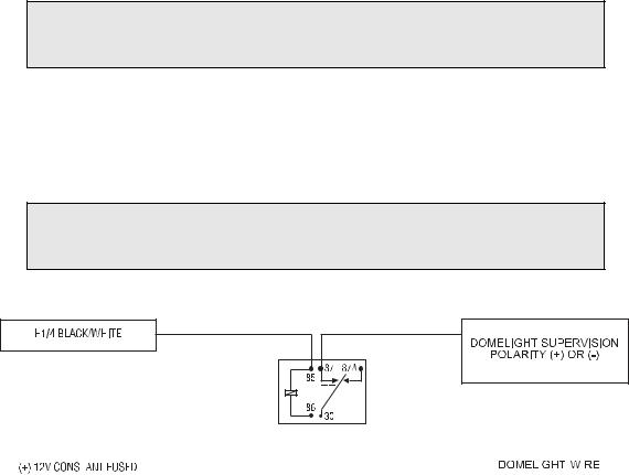
H1/4 BLACK/WHITE (-) 200 mA domelight supervision output
Connect the H1/4 wire to the optional domelight supervision relay as shown in the following
diagram:
IMPORTANT! This output is only intended to drive a relay. It cannot be connected directly to the domelight circuit, as the output cannot support the current draw of one or more bulbs.
|
|
|
|
|
|
|
|
|
|
|
|
|
|
|
|
|
|
|
|
|
|
|
|
|
|
|
|
|
|
|
|
|
|
|
|
|
|
|
|
|
|
|
|
|
|
|
|
|
|
|
|
|
|
|
|
|
|
|
|
|
|
|
|
|
|
|
|
|
|
|
|
|
|
|
|
|
|
|
|
|
|
|
|
|
|
|
|
6 |
|
|
|
|
© 2005 Directed Electronics, Inc. all rights reserved |
|||||
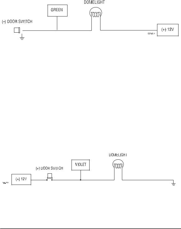
H1/5 GREEN (-) door trigger input
Most vehicles use negative door trigger circuits. Connect the green wire to a wire showing ground when any door is opened. When connecting to newer model vehicles there is generally a need to use individual door triggers. See DirectFax document 1076 for wiring instructions. This wire will report Zone 3.
NOTE: If using a door trigger wire that has a delay, Advanced Menu 2, feature 6 or the 998T Bitwriter can be used to turn Bypass Notification off.
H1/6 BLUE (-) instant trigger input
This input will respond to a negative input with an instant trigger. It is ideal for hood and trunk pins and will report on Zone 1. It can also be used with Directed single-stage sensors. The H1/6 blue instant trigger wire can also be used to shunt sensors during operation of auxiliary channels or remote start. (See Bypassing Sensor Inputs section of this guide.)
H1/7 VIOLET (+) door trigger input
This type of dome circuit is used in many Ford products. Connect the violet wire to a wire that shows (+)12V when any door is opened. This wire will report Zone 3.
NOTE: If using a door trigger wire that has a delay, Advanced Menu 2, feature 6 or the 998T Bitwriter can be used to turn Bypass Notification off.
© 2005 Directed Electronics, Inc. all rights reserved |
7 |
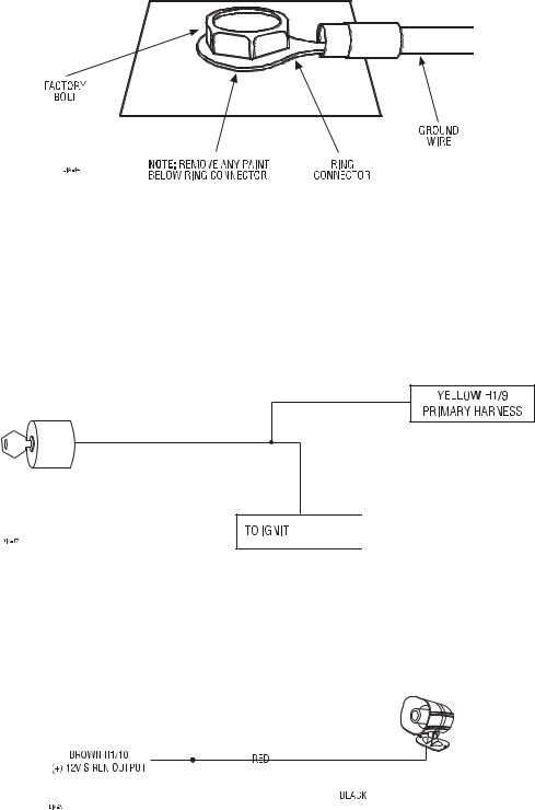
H1/8 BLACK (-) chassis ground connection
Connect this wire to a clean, paint-free sheet metal location (driver kick panel) using a factory bolt that DOES NOT have any vehicle component grounds attached to it. A screw should only be used when in conjunction with a two-sided lock washer. Under dash brackets and door sheet metal are not acceptable ground points. It is recommended that all security components be grounded at the same location.
H1/9 YELLOW (+) ignition input
Connect this wire to the (+) 12 volts ignition wire. This wire is pre-wired to the starter kill relay and must show (+) 12 volts with the key in RUN position and during cranking. Take great care that this wire cannot be shorted to the chassis at any point.
\\\\\\\


H1/10 BROWN (+) siren output
Connect this to the RED wire of the Revenger® siren. Connect the BLACK wire of the siren to (-) chassis ground, preferably at the same point you connect the control module’s BLACK ground wire.
|
|
|
|
|
|
|
|
|
|
|
|
|
|
|
|
|
|
|
|
|
|
|
|
|
|
|
|
|
|
|
|
|
|
|
|
|
|
|
|
|
|
|
|
|
|
|
|
|
|
|
|
|
|
|
|
|
|
|
|
|
|
|
|
|
|
|
|
|
|
|
|
|
|
|
|
|
|
|
|
|
|
|
|
|
|
|
|
|
|
|
|
|
|
|
|
|
|
|
|
|
|
|
|
|
|
|
|
|
|
|
|
|
|
|
|
|
|
|
|
|
|
|
|
|
|
|
|
|
|
|
|
|
|
|
|
|
|
|
|
8 |
|
|
|
|
|
|
|
|
|
© 2005 Directed Electronics, Inc. all rights reserved |
|||
H1/11 RED (+)12V constant power input
Before connecting this wire, remove the supplied fuse. Connect to the battery positive terminal or the constant 12V supply to the ignition switch.
NOTE: Always use a fuse within 12 inches of the point you obtain (+)12V. Do not use the 15 amp fuse in the harness for this purpose. This fuse protects the module itself.
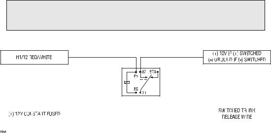
H1/12 RED/WHITE 200 mA (-) channel 2 output
When the system receives the code controlling channel 2 for longer than 1.5 seconds, the RED/WHITE will supply an output as long as the transmission continues. This is often used to operate a trunk/hatch release or other relay/driven function.
IMPORTANT! Never use this wire to drive anything but a relay or a low-current input! The transistorized output can only supply 200 mA of current. Connecting directly to a solenoid, motor, or other high-current device will cause it to fail.
|
|
|
|
|
|
|
|
|
|
|
|
|
|
|
|
|
|
|
|
|
|
|
|
|
|
|
|
|
|
|
|
|
|
|
|
|
|
|
|
|
|
|
|
|
|
|
|
|
|
|
|
|
|
|
|
|
|
|
|
|
|
|
|
|
|
|
|
|
|
|
|
|
|
|
|
|
© 2005 Directed Electronics, Inc. all rights reserved |
9 |
|||||||||
 Loading...