

Diodes ZXTN25020DG User Manual
ZXTN25020DG
C
E
B
20V NPN high gain transistor in SOT223
Summary
BV
> 100V
CEX
BV
> 20V
CEO
BV
> 6V
ECX
I
= 7A
C(cont)
V
R
P
Complementary part number ZXTP25020DG
Description
Packaged in the SOT223 outline this new low saturation NPN transistor
offers extremely low on state losses making it ideal for use in DC-DC
circuits and various driving and power management functions.
< 48mV @ 1A
CE(sat)
= 31mΩ
CE(sat)
= 3.0W
D
Features
• Higher power dissipation SOT223 package
•High gain
• High peak current
• Low saturation voltage
• 100V forward blocking voltage
• 6V reverse blocking voltage
Applications
•DC - DC converters
• Motor drive
• Relay, lamp and solenoid drive
• Regulator circuits
Ordering information
Device Reel size
(inches)
ZXTN25020DGTA 7 12 1000
Tape width
(mm)
Quantity
per reel
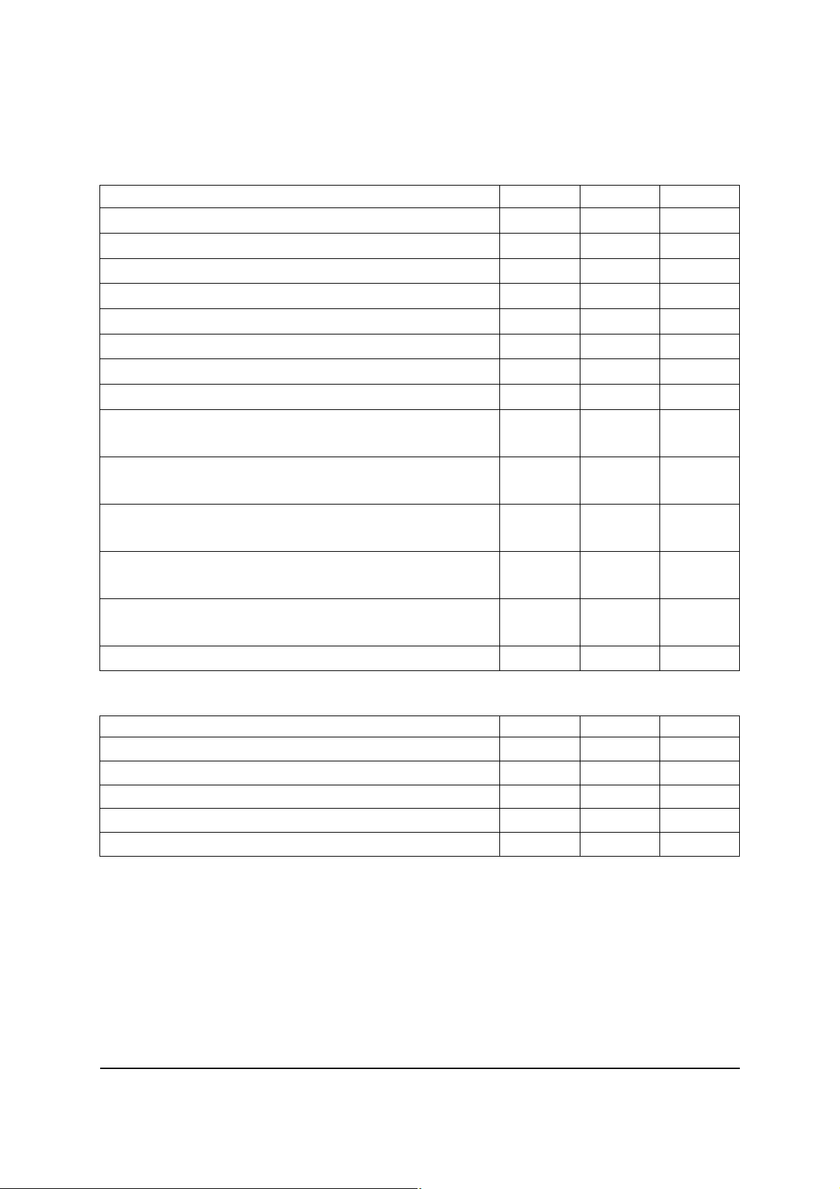
C
Pinout - top view
E
C
B
Device marking
ZXTN25
020D
Issue 1 - January 2008 1 www.zetex.com
© Zetex Semiconductors plc 2008
ZXTN25020DG
Absolute maximum ratings
Parameter Symbol Limit Unit
Collector-Base voltage V
Collector-Emitter voltage (forward blocking) V
Collector-Emitter voltage V
Emitter-Collector voltage (reverse blocking) V
Emitter-Base voltage V
Continuous Collector current
(c)
Base current I
Peak pulse current I
Power dissipation at T
=25°C
A
(a)
Linear derating factor
Power dissipation at T
=25°C
A
(b)
Linear derating factor
Power dissipation at T
=25°C
A
(c)
Linear derating factor
Power dissipation at T
=25°C
A
(d)
Linear derating factor
Power dissipation at T
=25°C
C
(e)
Linear derating factor
Operating and storage temperature range T
CBO
CEX
CEO
ECX
EBO
CM
P
P
P
P
P
, T
j
I
C
B
D
D
D
D
D
stg
100 V
100 V
20 V
6V
7V
7A
1A
15 A
1.2
9.6
1.6
12.8
3.0
24
5.3
42
7.3
58
-55 to 150
W
mW/°C
W
mW/°C
W
mW/°C
W
mW/°C
W
mW/°C
°C
Thermal resistance
Parameter Symbol Limit Unit
Junction to ambient
Junction to ambient
Junction to ambient
Junction to ambient
Junction to case
NOTES:
(a) For a device surface mounted on 15mm x 15mm x 0.6mm FR4 PCB with high coverage of single sided 1oz copper, in
still air conditions.
(b) Mounted on 25mm x 25mm x 0.6mm FR4 PCB with high coverage of single sided 1oz copper, in still air conditions.
(c) Mounted on 50mm x 50mm x 0.6mm FR4 PCB with high coverage of single sided 2oz copper, in still air conditions.
(d) As (c) above measured at t<5 seconds.
(e) Junction to case (collector tab). Typical
(a)
(b)
(c)
(d)
(e)
Issue 1 - January 2008 2 www.zetex.com
© Zetex Semiconductors plc 2008
R
R
R
R
R
⍜JA
⍜JA
⍜JA
⍜JA
⍜JC
104 °C/W
78 °C/W
42 °C/W
23.5 °C/W
16 °C/W
 Loading...