

Page 1
AP2004
PWM BUCK CONTROLLER
Features
• PWM Buck Control Circuitry
• Operating voltage can be up to 27V
• Under voltage Lockout (UVLO) Protection
• Short Circuit Protection (SCP)
• Soft-start circuit
• Variable Oscillator Frequency -- 300Khz Max
• 1.25V voltage reference Output
• 8-pin SOP package
• SOP-8L: Available in “Green” Molding Compound
(No Br, Sb)
• Lead Free Finish/ RoHS Compliant (Note 1)
Applications
• Backlight inverter
• LCD Monitor
• CDROM, XDSL Product
• DC/DC converters in computers, etc.
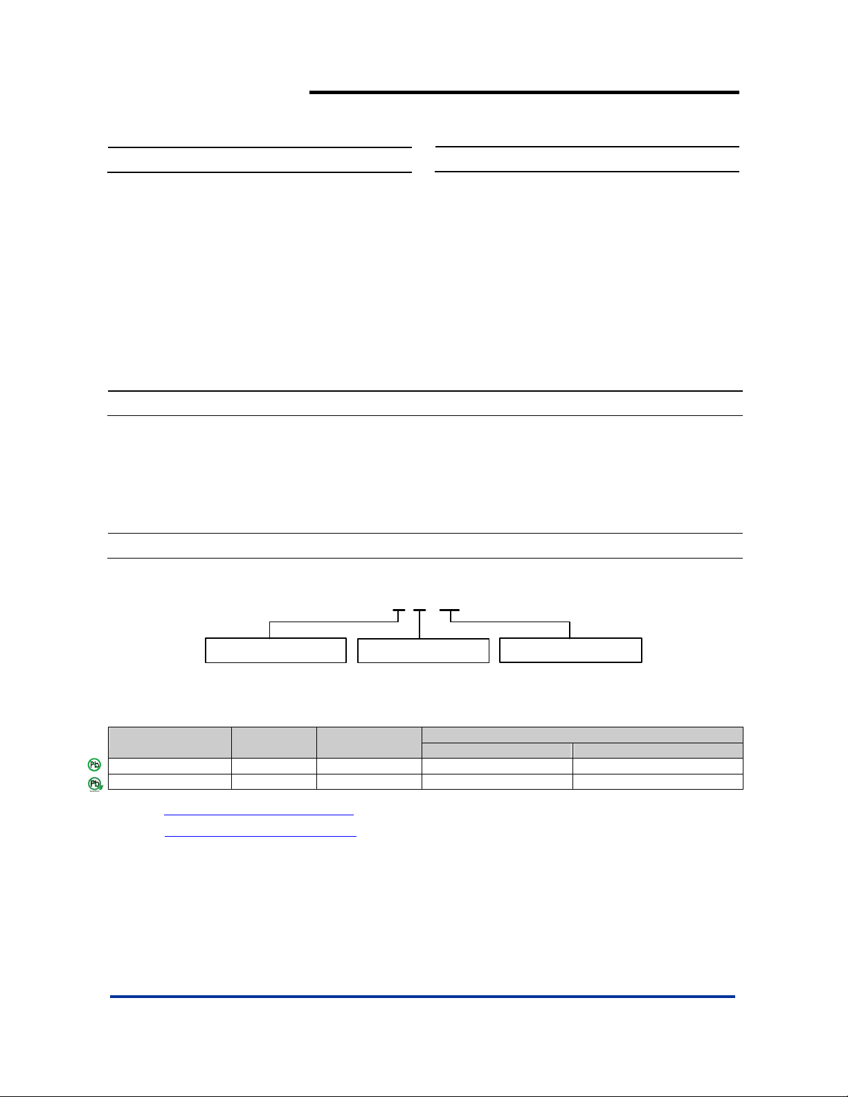
Ordering Information
AP 2004 S X - 13
General Description
The AP2004 integrates Pulse-Width-Modulation (PWM) control
circuit into a single chip, mainly designs for power-supply
regulator. All the functions include an on-chip 1.25V reference
output, an error amplifier, an adjustable oscillator, a soft-start,
UVLO, SCP circuitry, and a push-pull output circuit. Switching
frequency is adjustable by trimming CT. During low VCC situation,
the UVLO makes sure that the outputs are off until the internal
circuit operates normally.
Package PackingLead Free
S : SOP-8L
L : Lead Free
G : Green
Device
AP2004SL-13 S SOP-8L 2500/Tape & Reel -13
Lead-free
Package
Code
Packaging
(Note 2)
AP2004SG-13 S SOP-8L 2500/Tape & Reel -13
Notes: 1. EU Directive 2002/95/EC (RoHS). All applicable RoHS exemptions applied. Please visit our website at
http://www.diodes.com/products/lead_free.html
2. Pad layout as shown on Diodes Inc. suggested pad layout document AP02001, which can be found on our website at
http://www.diodes.com/datasheets/ap02001.pdf
.
.
AP2004 Rev. 3 1 of 8 FEBRUARY 2009
www.diodes.com © Diodes Incorporated
13 : Tape & Reel
13” Tape and Reel
Quantity Part Number Suffix
Page 2
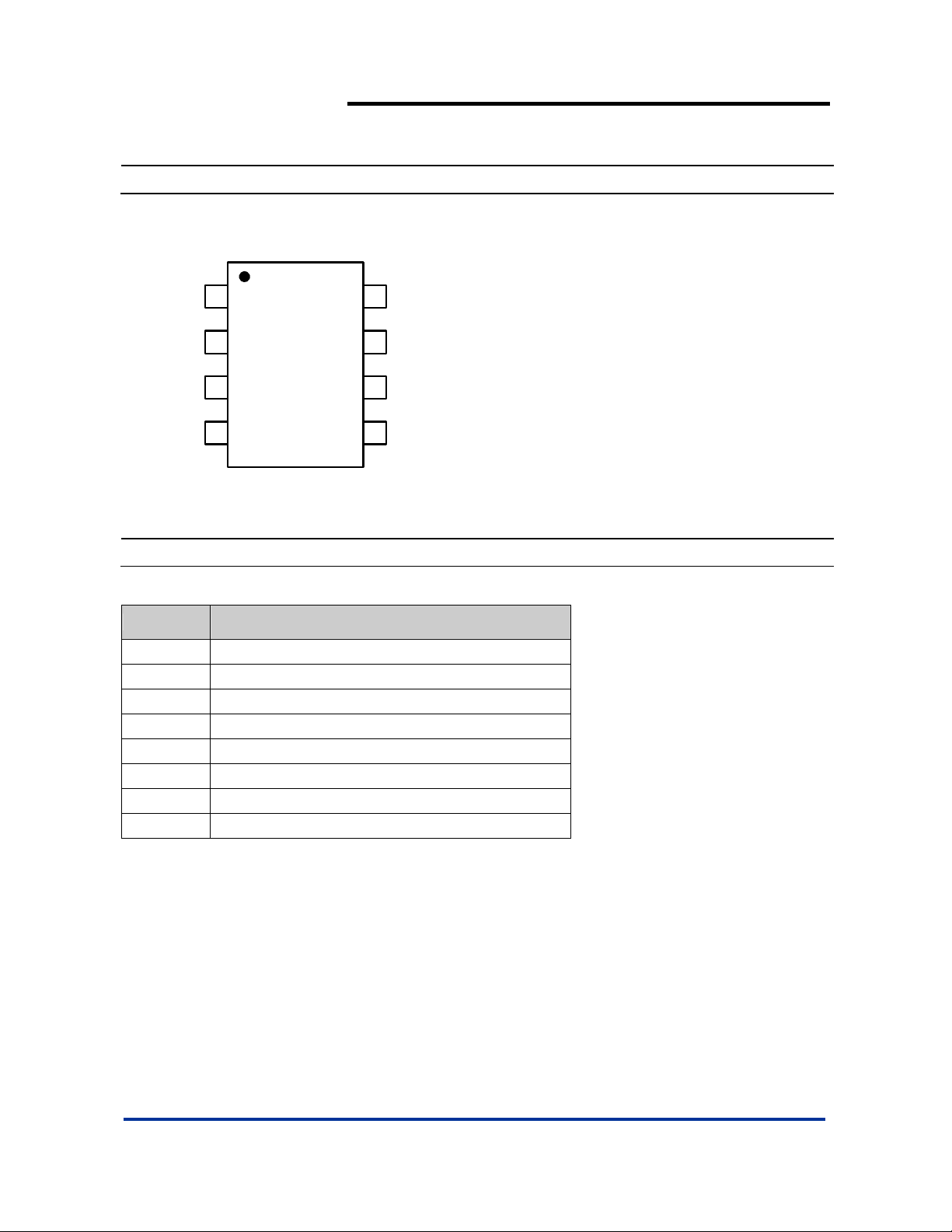
Pin Assignments
( Top View )
AP2004
PWM BUCK CONTROLLER
OUT
VCC
COMP
FB
1
2
3
4
SOP-8L
8
GND
CT
7
6
SS
5
SCP
Pin Descriptions
Pin Name Description
CT Timing Capacitor
FB Voltage Feedback
SS Soft-Start.
COMP Feedback Loop Compensation
OUT PWM Output
GND Ground
VCC Supply Voltage
SCP Short Circuit Protection
AP2004 Rev. 3 2 of 8 FEBRUARY 2009
www.diodes.com © Diodes Incorporated
Page 3
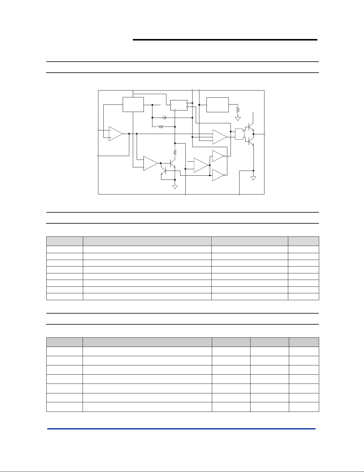
Block Diagram
AP2004
PWM BUCK CONTROLLER
FB
COMP
1.2 5V
Error Amplifier
VCC
Bandgap
Reference
1.5V
2.5V
Internal use
-
+
UVLO
Iss
SCP
0.7V
CT
SS
-
+
Oscillator
MAX. 300KHz
PWM Amplifier
+
+
-
GND
VCC
OUT
Absolute Maximum Ratings
Symbol Parameter Rating Unit
PD
Power dissipation at 25°C
600 mW
VCC Supply voltage 28 V
VI Amplifier input voltage 20 V
VO Collector output voltage VCC-1.0V V
I
Source current 200 mA
SOURCE
I
Sink current 200 mA
SINK
TOP Operating junction temperature range -20 to +125
T
Storage temperature range -65 to +150
ST
Recommended Operating Conditions
Symbol Parameter Min Max Unit
VCC Supply voltage 3.6 27 V
VI Amplifier input voltage 1.05 1.45 V
VO Collector output voltage Vcc-1.5 V
IFB Current into feedback terminal 45 µA
RF Feedback resistor 100 kΩ
CT Timing capacitor 100 6800 pF
F
Oscillator frequency 10 300 KHz
OSC
o
C
o
C
AP2004 Rev. 3 3 of 8 FEBRUARY 2009
www.diodes.com © Diodes Incorporated
Page 4

AP2004
PWM BUCK CONTROLLER
Electrical Characteristics (T
= 25ºC, V
A
= 6V, f = 200 Khz)
CC
Reference (REF)
Symbol Parameter Conditions Min Typ. Max Unit
Comp connect to FB 1.225 1.25 1.275 V
V
REF
Output voltage change with
temperature
= -20ºC ~ 25ºC -0.1 ±1 %
T
A
TA = 25ºC ~ 85ºC -0.2 ±1 %
Under voltage lockout (UVLO)
Symbol Parameter Conditions Min Typ. Max Unit
VUT Upper threshold voltage (VCC)
I
= 0.1mA
V
Lower threshold voltage (VCC) 2.4 V
LWT
VHT Hysteresis (VCC) 500 mV
O(REF)
T
= 25ºC
A
2.9 V
Short-circuit protection (SCP) control
Symbol Parameter Conditions Min Typ. Max Unit
VIT Input threshold voltage TA = 25ºC 0.60 0.67 0.75 V
V
Standby voltage No pull up 100 130 160 mV
STB
VLT Latched input voltage No pull up 50 100 mV
I
Input (source) current VI = 0.7V, TA = 25ºC -10 -15 -20 µA
SCP
VCT
Comparator threshold voltage
(COMP)
1.5 V
Oscillator (OSC)
Symbol Parameter Conditions Min Typ. Max Unit
F
Frequency CT = 270 pF 200 KHz
OSC
ΔF
OSC
Standard deviation of frequency C
Frequency change with voltage V
= 270 pF 10
T
= 3.6V ~ 20V 1
CC
%
Error-amplifier
Symbol
Parameter Conditions Min Typ. Max Unit
VIO Input offset voltage VO (FB) = 1.25V ±6 mV
IIO Input offset current VO (FB) = 1.25V ±100 nA
IIB Input bias current VO (FB) = 1.25V 160 500 nA
VCM Common-mode input voltage range V
= 3.6V ~ 20V 1.05 1.45 V
CC
AV Open-loop voltage amplification RF = 200 kΩ 70 80 dB
GBW Unity-gain bandwidth 1.5 MHz
CMRR Common-mode rejection ratio 60 80 dB
VOH Max. output voltage V
-0.1 V
ref
VOL Min. output voltage 1 V
IOI Output (sink) current (COMP) VID = -0.1V, VO = 1.25V 0.5 1.6 mA
IOO Output (source) current (COMP) VID = 0.1V, VO = 1.25V -45 -70 µA
AP2004 Rev. 3 4 of 8 FEBRUARY 2009
www.diodes.com © Diodes Incorporated
Page 5

AP2004
PWM BUCK CONTROLLER
Electrical Characteristics (Continued) (T
= 25ºC, V
A
= 6V, f = 200 Khz)
CC
Output section
Symbol Parameter Conditions Min Typ. Max Unit
I
Leakage current VO = 25V 10 µA
LEAK
I
V
DRV
SAT
Sink current V
Source current V
Output saturation voltage IO = 10 mA 1.0 1.5 V
= 20V 200 mA
IN
= 20V 200 mA
IN
ISC Short-circuit output current VO = 6V 120 mA
PWM comparator
Symbol Parameter Conditions Min Typ. Max Unit
VT0
V
T100
Input threshold voltage at f = 10 KHz
(COMP)
Maximum duty cycle 1.2 1.3 V
CT 0.6 0.7 V
Total device
Symbol Parameter Conditions Min Typ. Max Unit
I
Average supply current CT = 270pF 6 10 mA
CCA
Soft Start
Symbol Parameter Conditions Min Typ. Max Unit
VSS Soft-start Voltage 2.3 V
ISS Constant Charge Current 20 µA
Typical Application Circuit
R3 1K~30K
Vcc = 12V
C2
10nF
Optional
4 FB
SCP
5
3
COMP
SS
6
2
VCC
CT
7
1
OUT
GND
8
C4 270pF
C5 50nF
C6 220nF
Vout=Vref ⎟
Step-Down DC/DC converter
Q1
P mos
AF9435P
AF4835P
5A
⎛
1
⎜
⎝
C1
470uF
C4
50nF
Optional
Output
5V/5A
C3
470uF
L1
22uH
R1
9K
R2
3K
1
R
⎞
+
2
R
⎠
AP2004 Rev. 3 5 of 8 FEBRUARY 2009
www.diodes.com © Diodes Incorporated
Page 6

A
Typical Characteristics
REFERENCE OUTPUT VOLTAGE
vs.
POWER-SUPP LY VOLTAGE
1.26
1.255
1.25
1.245
1.24
1.235
Vref-
(V)
Reference
1.23
1.225
1.22
Output Voltage
4 8 12 16 20 24 28
Vcc-Power Supply Voltage (V)
AP2004
PWM BUCK CONTROLLER
VERAGE SUPPLY CURRENT
vs.
POWER-SUPPLY VOLTAGE
5
4
3
2
(mA)
1
Icc-Average
Supply Current
0
0 4 8 12 16 20 24 28
Vcc - Power-Supply Voltgae (V)
AVERAGE SUPPLY CURRENT
vs.
AMBIENT TEMPERATURE
7
6
5
(mA)
- Average
CC
I
4
3
Supply Current
2
-50 -25 0 25 50 75 100
TA - Ambient Temperatrure(℃)
OSCILLATOR FREQUENCY
vs.
350
300
250
200
150
(KHz)
100
fosc - Frequency
TIMING CAPACITANCE
50
0
100 600 1100 1600 2100 2600 3100 3600 4100 4600 5100 5600 6100 6600
CT-Timing Capacitor (pF)
(V)
CT
V
tscp-SCP Time-out
V
vs. Frequency
CT
1.6
1.4
1.2
1
0.8
0.6
0.4
0.2
0
0 100 200 300
Frequency (KHz)
SCP TIME-OUT PERIOD
vs.
35
30
25
20
15
10
Period (ms)
5
0
45 90 135 180 225 270 315 360 405 450 495
SCP CAPACITANCE
Cscp - SCP Capacitance (nF)
VCT(min)
VCT(max)
AP2004 Rev. 3 6 of 8 FEBRUARY 2009
www.diodes.com © Diodes Incorporated
Page 7

Typical Characteristics (Continued)
SOFT-START TIME (Ts)
vs.
SOFT-START CAPACITOR (Css)
30
25
20
15
10
Ts (mS)
5
0
25 50 75 100 125 150 175 200
Css (nF)
AP2004
PWM BUCK CONTROLLER
Marking Information
(1) SOP-8L
Logo
Part Number
( Top View )
8
5
AP2004
YY
WW X
X
41
L : Lead Free
G : Green
YY
: Year : 08, 09,10~
WW : Week : 01~52; 52
represents 52 and 53 week
X
: Internal Code
AP2004 Rev. 3 7 of 8 FEBRUARY 2009
www.diodes.com © Diodes Incorporated
Page 8

Package Information (All Dimensions in mm)
(1) Package Type: SOP- 8L
0.254
3.85/3.95
5.90/6.10
0.10/0.20
Detail "A"
0.62/0.82
Gauge Plane
Seating Plane
AP2004
PWM BUCK CONTROLLER
7°~9°
1.27typ
8x-0.60
6x-1.27
8x-1.55
Land Pattern Recommendation
0.3/0.5
4.85/4.95
(Unit: mm)
5.4
1.30/1.50
1.75max.
0.35max.
0.15/0.25
7°~9°
45°
Detail "A"
0°/8°
IMPORTANT NOTICE
Diodes Incorporated and its subsidiaries reserve the right to make modifications, enhancements, improvements, corrections or other changes without further
notice to any product herein. Diodes Incorporated does not assume any liability arising out of the application or use of any product described herein; neither
does it convey any license under its patent rights, nor the rights of others. The user of products in such applications shall assume all risks of such use and will
agree to hold Diodes Incorporated and all the companies whose products are represented on our website, harmless against all damages.
LIFE SUPPORT
Diodes Incorporated products are not authorized for use as critical components in life support devices or systems without the expressed written approval of the
President of Diodes Incorporated.
AP2004 Rev. 3 8 of 8 FEBRUARY 2009
www.diodes.com © Diodes Incorporated
 Loading...