

Page 1
AP1635
PWM/PFM DUAL MODE STEP-DOWN DC/DC
CONVERTER
Features
• Input voltage range: 2.2V~5V (V
• Oscillator frequency: 700KHz (Typ.)
• Internal reference: 1.0V (Typ.)
• High efficiency: 93% (Typ.)
• Current limit and thermal shutdown protection
• Lead Free Package: SOP-8L
• SOP-8L: Available in “Green” Molding Compound
(No Br, Sb)
• Lead Free Finish/ RoHS Compliant (Note 1)
OUT
type)
Applications
• Electronic Information Organizers
• Palmtops
• Cellular and portable phones
• Portable Audio Systems
• Various Multi-function Power Supplies
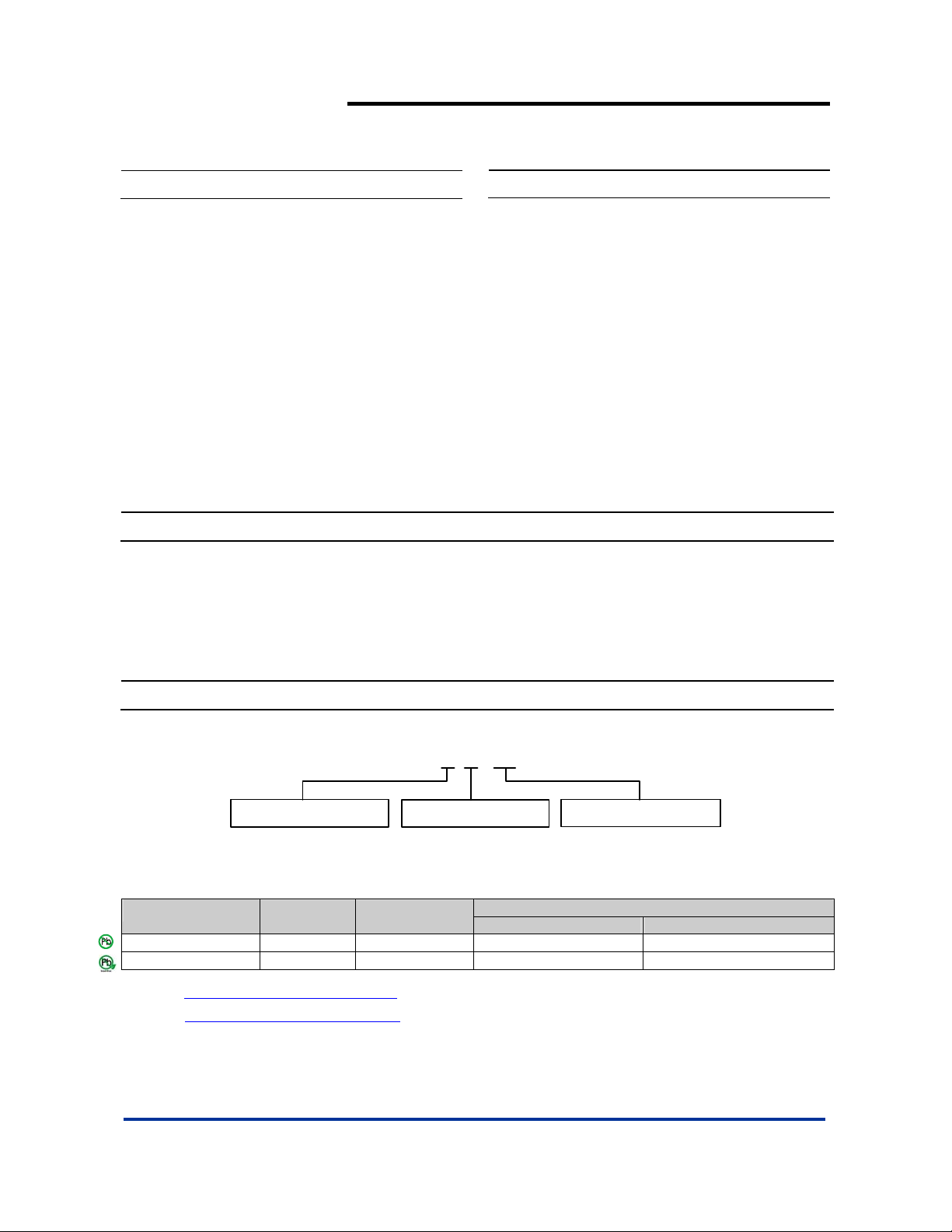
Ordering Information
AP 1635 S X - 13
General Description
The AP1635 series are multi-functional step-down DC/DC
converters with built-in speed, low ON resistance drivers. It is
capable to deliver more than 1.2A output current with external
coil, diode and ca pacitor.
Output voltage is set-up by the external resistors. (±2.5%
accuracy). The 700KHz AP1635 that can work out with small
value external components comes out more compact board.
The device switches to and works under PFM mode with light
loads. It keeps at high efficiency for both light loads and large
output current.
AP1635 can be soft-start with a proper capacitor connected
between CE/SS pin and ground. The stand-by current is less
than 6uA when CE/SS pin is at “LOW” status. The device is
forced to switch off as the voltage at that pin is lower than the
stipulated voltage.
Package PackingLead Free
S : SOP-8L
L : Lead Free
G : Green
Device
AP1635SL-13 S SOP-8L 2500/Tape & Reel -13
Lead-free
Package
Code
Packaging
(Note 2)
AP1635SG-13 S SOP-8L 2500/Tape & Reel -13
Notes: 1. EU Directive 2002/95/EC (RoHS). All applicable RoHS exemptions applied. Please visit our website at
http://www.diodes.com/products/lead_free.html
2. Pad layout as shown on Diodes Inc. suggested pad layout document AP02001, which can be found on our website at
http://www.diodes.com/datasheets/ap02001.pdf
.
.
AP1635 Rev. 4 1 of 8 FEBRUARY 2009
www.diodes.com © Diodes Incorporated
13 : Tape & Reel
13” Tape and Reel
Quantity Part Number Suffix
Page 2
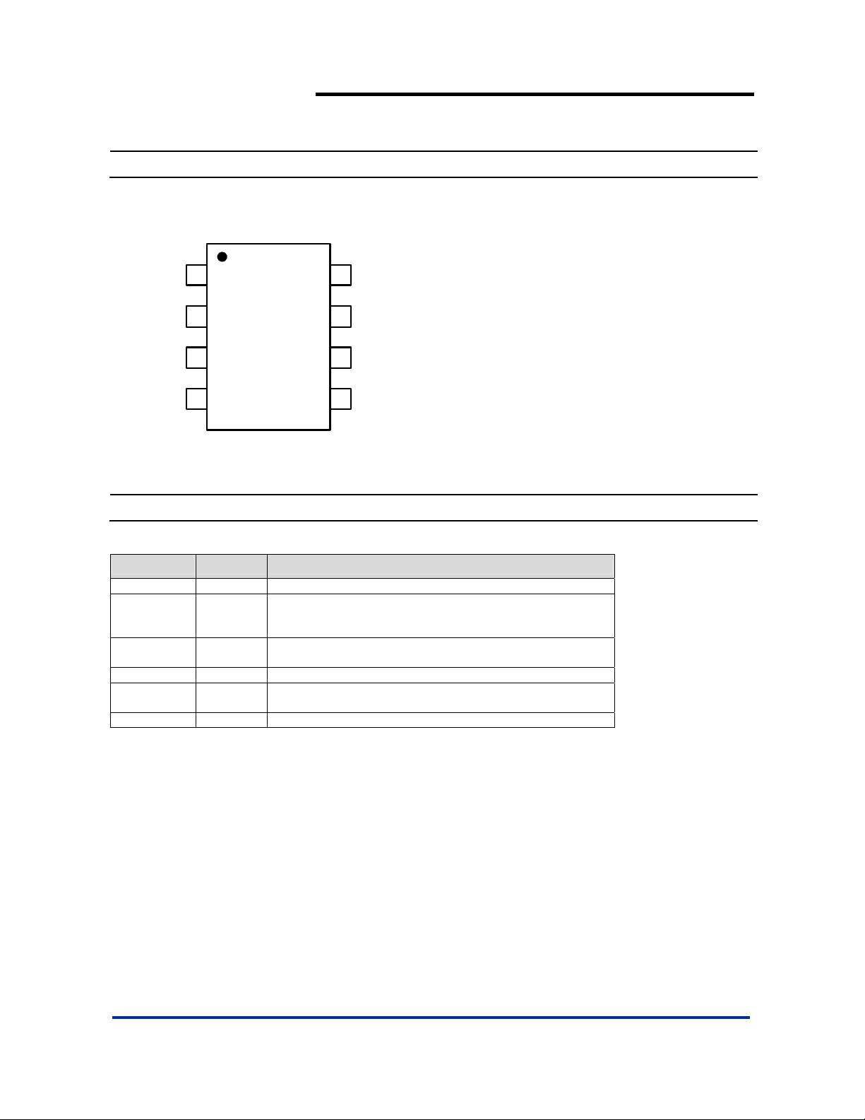
Pin Assignments
( Top View )
AP1635
PWM/PFM DUAL MODE STEP-DOWN DC/DC
CONVERTER
FB
CE/SS
SVcc
PVcc
1
2
3
4
SOP-8L
8
GND
GND
7
SW
6
5
SW
Pin Descriptions
Pin Name Pin No. Description
FB 1 Feedback pin
Chip Enable/ Soft Start:
CE/SS 2
SVcc 3
PVcc 4 IC power supply pin
SW 5/6
GND 7/8 GND Pin
H: Enable
L: Disable
IC signal power supply pin, add a 20Ω re sistor to P Vcc a nd a
0.1µF capacitor to GND.
Switch Pin. Connect external inductor/diode here. Minimize
trace area at this pin to reduce EMI.
AP1635 Rev. 4 2 of 8 FEBRUARY 2009
www.diodes.com © Diodes Incorporated
Page 3
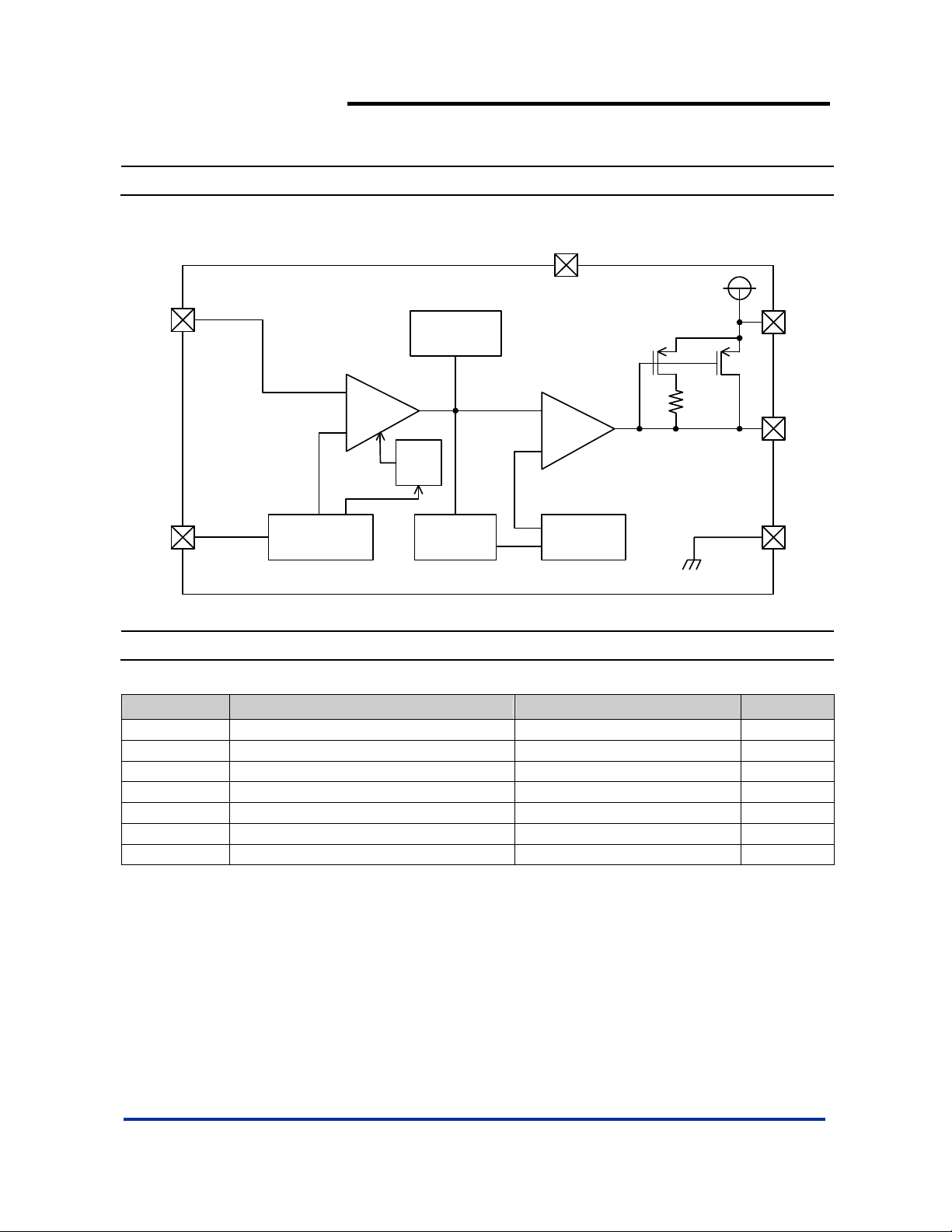
Block Diagram
AP1635
PWM/PFM DUAL MODE STEP-DOWN DC/DC
CONVERTER
SVcc
FB
Phase
Compensation
Current Limit
PVcc
+
ERR
AMP
-
Soft
Start
CE/SS GND
Vref with
CE
Absolute Maximum Ratings (T
Symbol Parameter Ratings Units
VCC/SVCC VIN Pin Voltage -0.3 ~ 5.0 V
VSW SW Pin Voltage -0.3 ~ VIN+0.3 V
VFB FB Pin Voltage -0.3 ~ VIN+0.3 V
V
CE/SS Pin Voltage -0.3 ~ VIN+0.3 V
CE/SS
PD Continuous Total Power Dissipation Internal limited
T
Operating Ambient Temperature -25 ~ +80 °C
OPR
T
Storage Temperature -40 ~ +125 °C
STG
PWM/PFM
Controller
=25°C)
A
+
-
Comparator
Ramp Wave
Generator,
OSC
SW
PWM
AP1635 Rev. 4 3 of 8 FEBRUARY 2009
www.diodes.com © Diodes Incorporated
Page 4

AP1635
PWM/PFM DUAL MODE STEP-DOWN DC/DC
CONVERTER
Electrical Characteristics
V
=5V, V
IN
Symbol Parameter Conditions Min Typ. Max Units
VFB FB 0.975 1.0 1.025 V
VIN Input Voltage 2.2 - 5 V
Line Regulation VIN=2.2~5V, Load=10mA - - 0.12 %
Load Regulation I
V
UVLO
ICC Operating Current CE/SS=VIN,No Load - 100 150 μA
I
CCQ
I
STB
ICL Current Limit
Fosc Oscillator Frequency Load=300mA, VIN=5V, V
MAXDTY Maximum Duty Ratio 85 90 - %
PFMDTY PFM Duty Ratio No load 15 25 35 %
V
CEH
V
CEL
EFFI Efficiency VCC=5V, V
Rdson Rdson Condition I
=2V, Load=300mA, TA=25°C
OUT
=10~1200mA - - 1.2 %
OUT
UVLO Voltage(min.
operating voltage)
Supply Current
Stand-by Current
VCC, voltage required to maintain H at V
No external components,
CE/SS=V
No external components,
CE/SS=0V,V
Peak current
=5V, V
V
IN
CE/SS ”High” Voltage
Apply 1.4V (min.) to CE/SS, determine
V
“High”
OUT
CE/SS ”Low” Voltage Same as V
=300mA, VIN=5V, V
OUT
- - 2 V
OUT
IN,VFB
FB
=2V
OUT
=1.2V
=0V
=2V 500 700 - kHz
OUT
- 90 120 μA
- 6 - μA
1200 1400 1600 mA
1.4 - - V
, determine V
CEH
=3.3V, Load=300mA - 93 - %
OUT
OUT
/“Low” - - 0.6 V
OUT
=2V - 350 450 mΩ
AP1635 Rev. 4 4 of 8 FEBRUARY 2009
www.diodes.com © Diodes Incorporated
Page 5

V
V
)
V
V
V
V
)
cc
AP1635
PWM/PFM DUAL MODE STEP-DOWN DC/DC
CONVERTER
Typical Performance Characteristics
cc vs. Operating Current
200
Icc (uA)
180
160
140
120
100
80
60
40
Operating Current (uA)
20
0
2.5 3 3.5 4 4.5 5
Vcc (V
200
180
160
140
120
100
Quiescent Current (uA)
cc vs. Stand-by Cur ren t
8
7.5
7
6.5
6
5.5
5
4.5
Stand-by Current (uA)
4
2.533.544.55
Vcc (V)
800
780
760
740
720
700
680
660
Frequency (KHz)
640
620
600
cc vs. Current Limit
1.4
1.3
1.2
1.1
0.9
0.8
0.7
Current Limit (A)
0.6
0.5
Curren t Limit
1
Vout=2V
33.544.55
V
600
500
400
(mΩ)
300
DS(ON )
200
R
100
AP1635 Rev. 4 5 of 8 FEBRUARY 2009
www.diodes.com © Diodes Incorporated
cc vs. Quiescent Current
80
60
40
20
0
2.533.544.55
Vcc (V)
cc vs. Frequency
2.5 3 3.5 4 4.5 5
0
2.5 3 3.5 4 4.5 5
Vcc (V)
cc vs. R
Vcc ( V)
DS(ON
Page 6

×
PWM/PFM DUAL MODE STEP-DOWN DC/DC
Typical Performance Characteristics (Continued)
Line Regulation Load Regulation
0.3
3
AP1635
CONVERTER
0.2
0.1
(%)
0.0
OUT
-0.1
V / V
-0.2
-0.3
2.5 3 3.5 4 4.5 5
Vcc (V)
Typical Application Circuit
2.2V ~ 5.5V
V
IN
20
Ω
68u
0.1uF
1M
Ω
PVcc
AP1635
SVcc
GND
CE/SS
1nF
Vout = 1
R1=100K ~ 200K
2
1
(%)
0
OUT
-1
V / V
-2
-3
0 200 400 600 800 1000 1200
10uH
B240A R2
)
(1 +
SW
FB
R2
R1
Load (mA)
R1
0.1uF 68uF
V
OUT
AP1635 Rev. 4 6 of 8 FEBRUARY 2009
www.diodes.com © Diodes Incorporated
Page 7

Marking Information
(1) SOP-8L
AP1635
PWM/PFM DUAL MODE STEP-DOWN DC/DC
CONVERTER
( Top View )
8
5
Logo
Part Number
AP1635
YY
WW X
X
41
Package Information (All Dimensions in mm)
(1) Package Type: SOP-8L
0.254
0.62/0.82
7°~9°
Gauge Plane
Seating Plane
Detail "A"
7°~9°
1.27typ
4.85/4.95
0.3/0.5
3.85/3.95
1.30/1.50
5.90/6.10
1.75max.
0.15/0.25
0.10/0.20
0.35max.
Detail "A"
45°
L : Lead Free
G : Green
: Year : 08, 09,10~
YY
WW : Week : 01~52; 52
represents 52 and 53 week
: Internal Code
X
0°/8°
8x-0.60
5.4
6x-1.27
8x-1.55
Land Pattern Recommendation
(Unit: mm)
AP1635 Rev. 4 7 of 8 FEBRUARY 2009
www.diodes.com © Diodes Incorporated
Page 8

AP1635
PWM/PFM DUAL MODE STEP-DOWN DC/DC
CONVERTER
IMPORTANT NOTICE
Diodes Incorporated and its subsidiaries reserve the right to make modifications, enhancements, improvements, corrections or other changes without further
notice to any product herein. Diodes Incorporated does not assume any liability arising out of the application or use of any product described herein; neither
does it convey any license under its patent rights, nor the rights of others. The user of products in such applications shall assume all risks of such use and will
agree to hold Diodes Incorporated and all the companies whose products are represented on our website, harmless against all damages.
LIFE SUPPORT
Diodes Incorporated products are not authorized for use as critical components in life support devices or systems without the expressed written approval of the
President of Diodes Incorporated.
AP1635 Rev. 4 8 of 8 FEBRUARY 2009
www.diodes.com © Diodes Incorporated
 Loading...