

Page 1
AP1605
PWM/PFM DUAL-MODE STEP-DOWN SWITCHING
REGULATOR
Features
• Low current consum ption:
In operation: 100µA max.
Power off: 2µA max.
• Input voltage: 2.5V to 7V
Adjustable version (+
• PWM/PFM dual Mode
• Oscillation frequency: 300KHz (Typ.)
• With a power-off function.
• Built-in internal SW P-channel MOS
• Lead Free package: SOP-8L
• SOP-8L: Available in “Green” Molding Compound
(No Br, Sb)
• Lead Free Finish/ RoHS Compliant (Note 1)
2.5%)
Applications
• On-board power supply of battery
devices for portable telephones,
electronic notebooks, PDA, and other
hand-held sets
• Power supplies for audio equipment,
including portable CD players and
headphone stereo equipment
• Fixed voltage power s upply for cameras,
video equipment and communications
equipment
• Power supplies for microcomputers.
• Conversion from four Ni-H or Ni-Cd cells or
two lithium-ion cells to 3.3V/3V
• Conversion of AC adapter input to 5V/3V
General Description
AP1605 consists of CMOS step-down switching regulator with
PWM/PFM dual mode control. These devices include a reference
voltage source, oscillation circuit, error amplifier, internal P M OS a nd
etc.
AP1605 provides low-ripple power, high efficiency, and excellent
transient characteristics. The PWM/PFM control circuit is able to
vary the duty ratio linearly 0%~0.25% (PFM) and 25%~100%
(PWM).
With the addition of an internal P-channel Power MOS, a coil,
capacitors, and a diode connected externally, these ICs can function
as step-down switching regulators. They serve as ideal power
supply units for portable devices when coupl ed with the SOP-8L
mini-package, providing such outstanding features as low current
consumption. Since this converter can accommodate an input
voltage of up to 7V, it is also ideal when operating via an AC
adapter.
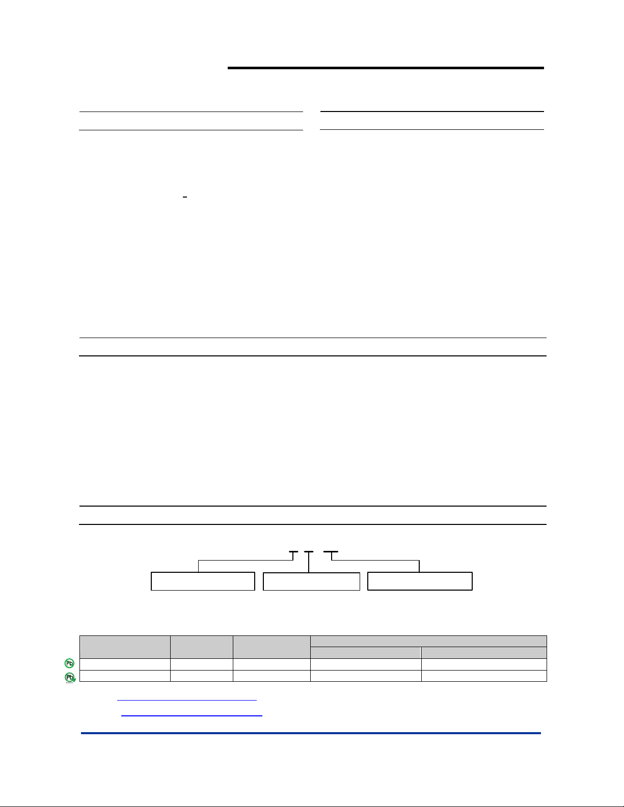
Ordering Information
AP 1605 S X - 13
Package PackingLead Free
S : SOP-8L
L : Lead Free
G : Green
Device
AP1605SL-13 S SOP-8L 2500/Tape & Reel -13
Lead-free
Package
Code
Packaging
(Note 2)
AP1605SG-13 S SOP-8L 2500/Tape & Reel -13
Notes: 1. EU Directive 2002/95/EC (RoHS). All applicable RoHS exemptions applied. Please visit our website at
http://www.diodes.com/products/lead_free.html
2. Pad layout as shown on Diodes Inc. suggested pad layout document AP02001, which can be found on our website at
http://www.diodes.com/datasheets/ap02001.pdf
.
.
AP1605 Rev. 2 1 of 8 FEBRUARY 2009
www.diodes.com © Diodes Incorporated
13 : Tape & Reel
13” Tape and Reel
Quantity Part Number Suffix
Page 2
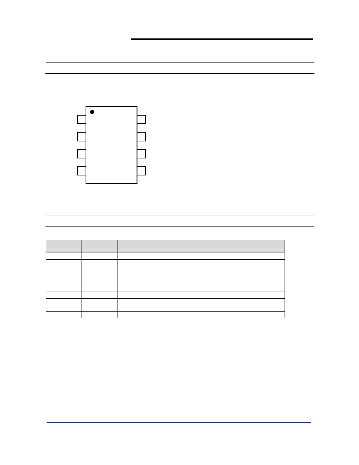
Pin Assignments
( Top View )
AP1605
PWM/PFM DUAL-MODE STEP-DOWN SWITCHING
REGULATOR
FB
CE
Vcc
PVcc
1
2
3
4
SOP-8L
8
Vss
Vss
7
SW
6
5
SW
Pin Descriptions
Pin Name Pin No. Description
FB 1 Feedback pin
Chip Enable:
CE 2
Vcc 3
PVcc 4 IC power supply pin
SW 5, 6
Vss 7, 8 GND Pin
H: Enable
L: Disable
IC signal power supply pin, add a 10Ω resistor to PVc c an d a 0. 1µF
capacitor to GND.
Switch Pin. Connect external inductor/diode here. Minimize trace
area at this pin to reduce EMI.
AP1605 Rev. 2 2 of 8 FEBRUARY 2009
www.diodes.com © Diodes Incorporated
Page 3
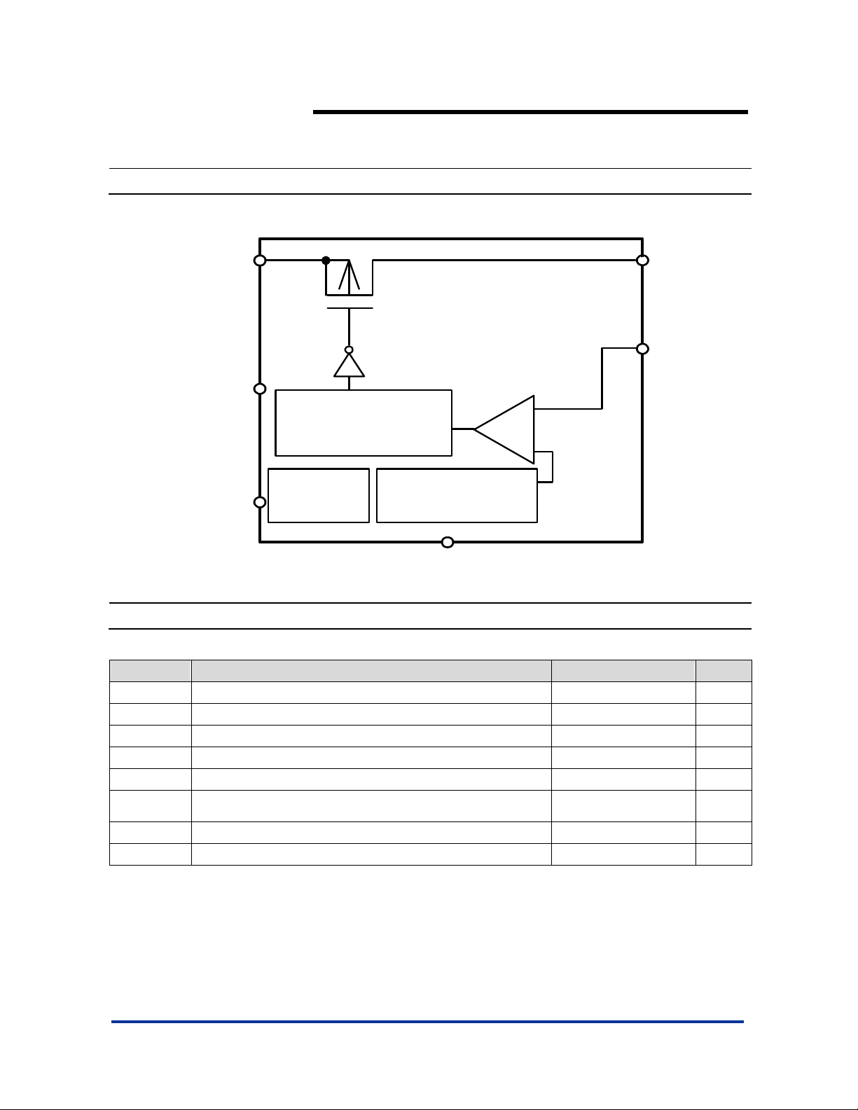
Block Diagram
AP1605
PWM/PFM DUAL-MODE STEP-DOWN SWITCHING
REGULATOR
PV
CC
SW
FB
AP1605
V
CC
PWM/PFM- Switched
+
Control Circuit
-
CE
Oscillation
Circuit
Reference Voltage
Source
V
SS
Absolute Maximum Ratings
Symbol Parameter Rating Unit
VCC VCC Pin Voltage VSS - 0.3 to VSS + 8 V
PVCC PVCC Pin Voltage VSS - 0.3 to VSS + 8 V
FB FB Pin Voltage VSS - 0.3 to VSS + 8 V
VCE ON/OFF Pin Voltage VSS - 0.3 to VSS + 8 V
VSW Switch Pin Voltage VSS - 0.3 to VIN + 0.3 V
PD Power Dissi pation 1200 mW
T
Operating Temperature Range -20 to +85
OPR
T
Storage Temperature Range -20 to +125
STG
Caution: The absolute maximum ratings are rated values exceeding which the product could suffer physical damage. These values must therefore not be
AP1605 Rev. 2 3 of 8 FEBRUARY 2009
exceeded under any conditions.
www.diodes.com © Diodes Incorporated
o
C
o
C
Page 4

AP1605
PWM/PFM DUAL-MODE STEP-DOWN SWITCHING
REGULATOR
Electrical Characteristics (VIN = 5V, T
= 25°C, unless otherwise specified)
A
Symbol Parameter Conditions Min. Typ. Max. Unit
VIN Input Voltage AP1605 Series 2.5 -- 7 V
V
Internal Reference Voltage 1.1625 1.2 1.2375 V
REF
V
UVLO Voltage Voltage required to maintain V
UVLO
OUT
-- -- 2.2 V
MAXDTY Maximum Duty Ratio 100 -- -- %
PFMDTY PFM Duty Ratio 15 25 35 %
ISW Switch Current Duty = 50% 3 -- -- A
Current Consumption
ISS
POWER
I
∆V
∆V
F
V
V
Current Consumption
SSS
During Power Off
Line Regulation 2.5V~7V @ I
OUT1
Load Regulation 0.1A~3A -- 1 1.5 %
OUT2
Oscillation Frequency 220 300 380 KHz
OSC
CE Pin “High” Voltage Evaluate oscillation at SW pin 0.65 -- --
CEH
CE Pin “Low” Voltage
CEL
ISH
Power-Off Pin Input
Leakage Current
ISL -- -0.1 -- 0.1 µA
ON
EFFI Efficiency VIN = 5V, V
V
= 2.5V -- 35 100 µA
OUT
V
= 0V -- -- 2 µA
ON/OFF
= 0.1A -- 0.2 0.5 %
OUT
Evaluate oscillation stop at SW
pin
-- -- 0.2
*Vcc
-- -0.1 -- 0.1 µA
= 2.5V I
OUT
= 1A -- 93 -- %
OUT
AP1605 Rev. 2 4 of 8 FEBRUARY 2009
www.diodes.com © Diodes Incorporated
Page 5

Typical Application Circuit
(1) Normal Application
PVCC SW
RVCC
VCC
CVCC
R
CE
100K
CE
C
CE
0.1uF
AP1605
PWM/PFM DUAL-MODE STEP-DOWN SWITCHING
REGULATOR
OUT
C
R
C
A
AP1605
V
SS
FB
R
B
=~200K
D1
+
-
R
A
)
(1VFB
Vout
+×=
R
B
(2) Application with Short Circuit Protection
VIN : 2.5V~7V
CPVCC
100uF
DVCC
1N4148 for above 5V Vin and
Schottky for below 5V Vin
R
ON/OFF
3.5M
RBias
10M
CVCC
0.1uF
CON/OFF
0.2uF
RSENCE
1M
PVCC
VCC
CE
V
SS
AP1605
SW
C
R
C
FB
R
=~10K
D1
OUT : 1.8V
V
A
+
B
COUTPUT
100uF
-
Vout
=
VFB
R
A
(1
)
+×
R
B
AP1605 Rev. 2 5 of 8 FEBRUARY 2009
www.diodes.com © Diodes Incorporated
Page 6

Test Circuit
AP1605
PWM/PFM DUAL-MODE STEP-DOWN SWITCHING
REGULATOR
Functional Description
PWM/PFM Control (AP1605 Series)
The AP1605 consists of DC/DC converters that employ a PWM/PFM auto-switch system.
In converters of the AP1605, the PFM m ode varies in a ra nge of duty cycle f rom 0 % to 2 5%, a nd the P WM mode v aries in a range of duty
cycle from 25% to 100% according to the load current, and yet ripple voltage produced by the switching can ea sily be removed through a
filter because the switching frequency remains constant. Therefore, these converters provide a low-ripple power over broad ranges of
input voltage and load current.
AP1605 Rev. 2 6 of 8 FEBRUARY 2009
www.diodes.com © Diodes Incorporated
Page 7

Marking Information
(1) SOP-8L
AP1605
PWM/PFM DUAL-MODE STEP-DOWN SWITCHING
REGULATOR
( Top View )
8
5
Logo
Part Number
AP1605
WW X
YY
X
41
Package Information ( All Dimensions in mm )
(1) Package Type: SOP-8L
0.254
0.62/0.82
7°~9°
Gauge Plane
Seating Plane
Detail "A"
0°/8°
7°~9°
1.27typ
4.85/4.95
0.3/0.5
3.85/3.95
1.30/1.50
5.90/6.10
1.75max.
0.10/0.20
0.15/0.25
Detail "A"
0.35max.
45°
L : Lead Free
G : Green
YY
: Year : 08, 09,10~
WW : Week : 01~52; 52
represents 52 and 53 week
: Internal Code
X
8x-0.60
5.4
6x-1.27
8x-1.55
Land Pattern Recommendation
(Unit: mm)
AP1605 Rev. 2 7 of 8 FEBRUARY 2009
www.diodes.com © Diodes Incorporated
Page 8

AP1605
PWM/PFM DUAL-MODE STEP-DOWN SWITCHING
REGULATOR
IMPORTANT NOTICE
Diodes Incorporated and its subsidiaries reserve the right to make modifications, enhancements, improvements, corrections or other changes without further
notice to any product herein. Diodes Incorporated does not assume any liability arising out of the application or use of any product described herein; neither
does it convey any license under its patent rights, nor the rights of others. The user of products in such applications shall assume all risks of such use and will
agree to hold Diodes Incorporated and all the companies whose products are represented on our website, harmless against all damages.
LIFE SUPPORT
Diodes Incorporated products are not authorized for use as critical components in life support devices or systems without the expressed written approval of the
President of Diodes Incorporated.
AP1605 Rev. 2 8 of 8 FEBRUARY 2009
www.diodes.com © Diodes Incorporated
 Loading...