

Diodes AL8843EV1 User Manual
AL8843EV1 User Guide
Parameter
Value
Input Voltage
5VDC to 40VDC
LED Current
2A
Number of LEDs
1~10 LEDs
XYZ Dimension
63mm x 40mm x 10mm
General Description
The AL8843 is a hysteresis mode DC-DC
step-down converter, designed for driving
single or multiple series connected LEDs
efficiently from a voltage source higher
than the LED voltage. The device can
operate from an input supply between 4.5V
and 40V and provide an externally
adjustable output current up to 3A.
Depending upon supply voltage and
external components, this converter can
provide up to 60W of output power.
The AL8843 integrates the power switch
and a high-side output current sensing
circuit, which uses an external resistor to
set the nominal average output current.
Dimming can be realized by applying an
external control signal to the CTRL Pin. The
CTRL Pin will accept either a DC voltage
signal or a PWM signal.
The soft-start time can be adjusted by an
external capacitor from the CTRL Pin to
Ground. Applying a voltage of 0.3V or lower
to the CTRL Pin will shut down the power
switch.
Applications
LED Retrofit for Low Voltage Halogen
Low Voltage Industrial Lighting
LED Backlighting
Illuminated Signs
External Driver with Multiple Channels
Key Features
Wide Input Voltage Range: 4.5V to 40V
Output Current up to 3A
Internal 40V NDMOS Switch
Typical 4% Output Current Accuracy
Single Pin for On/Off and Brightness
Control by DC Voltage or PWM Signal
Recommended Analog Dimming Range:
10% to 100%
Soft-Start
High Efficiency (Up to 97%)
LED Short Protection
Inherent Open-Circuit LED Protection
Over Temperature Protection (OTP)
Up to 1MHz Switching Frequency
SO-8EP Packages Available in Green
Molding Compound (No Br, Sb)
AL8843EV1 Specifications
AL8843EV1 Page 1 of 10
Dec 2017
www.diodes.com
AL8843EV1 User Guide
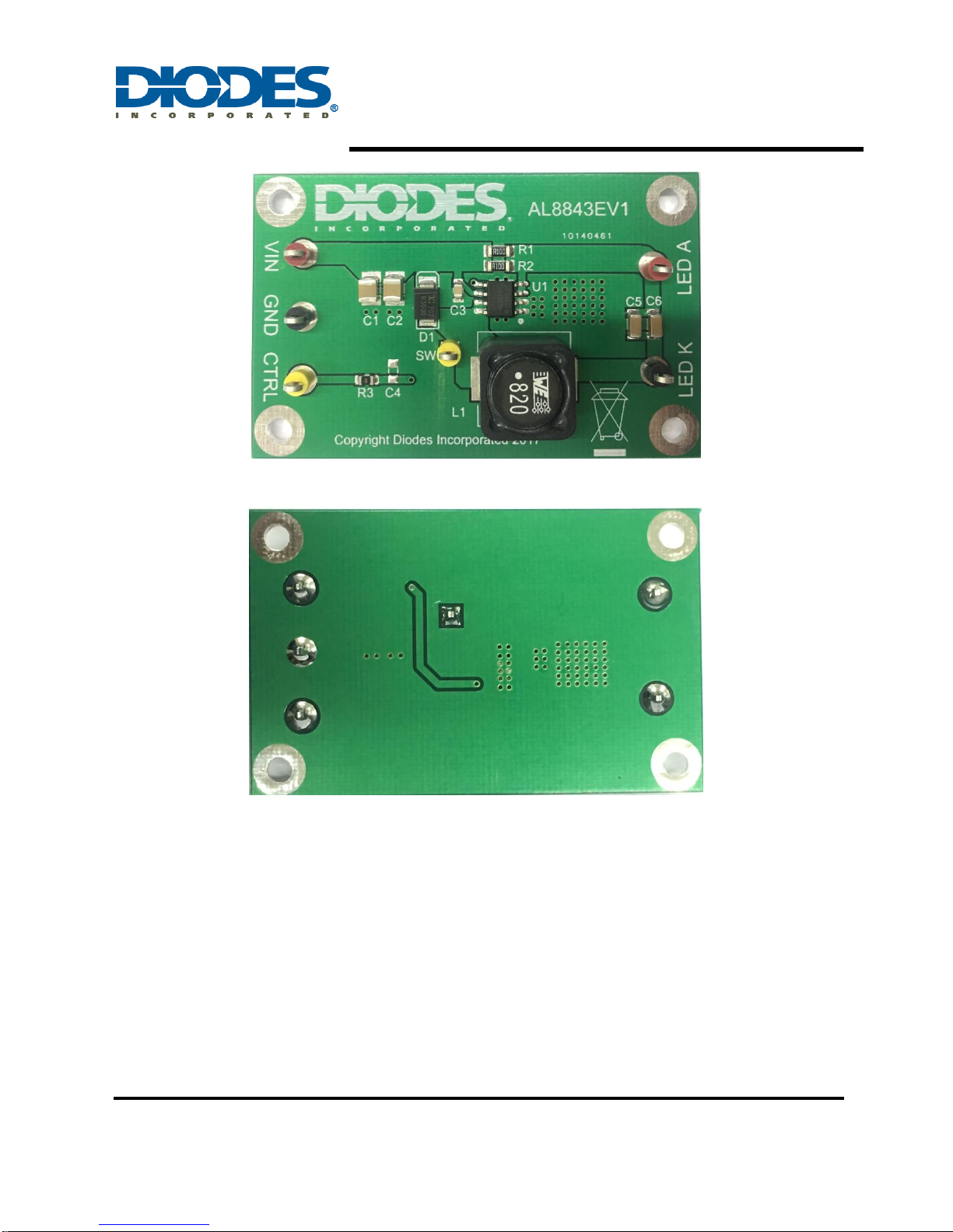
Figure 1: Top View
Connection Instructions
Power Supply Input: 5~40VDC (VIN, GND)
CTRL: Internal voltage ref. pin (2.5V). This pin can be used to achieve dimming and for switching
the output current off. Leave floating for normal operation.
PWM Signal Input: Remove C4, apply PWM signal to CTRL (CTRL, GND)
Analog Signal Input: Connect 470nF capacitor to C4, apply analog signal to CTRL (CTRL, GND)
LED A: LED A connects to the external LED anode
LED K: LED K connects to the external LED cathode
AL8843EV1 Page 2 of 10
Dec 2017
www.diodes.com
Figure 2: Bottom View
AL8843EV1 User Guide
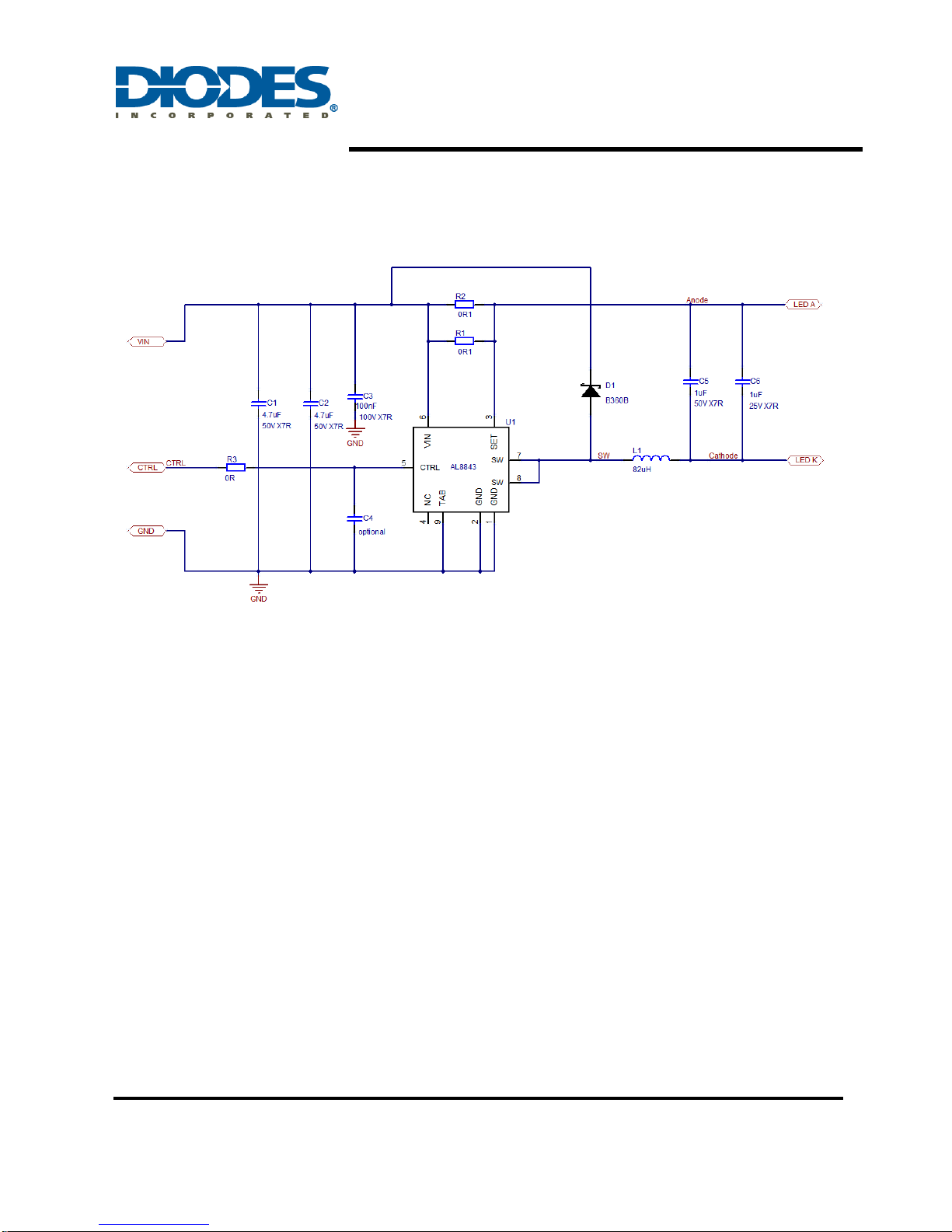
Evaluation Board Schematic
Figure 3: Evaluation Board Schematic
AL8843EV1 Page 3 of 10
Dec 2017
www.diodes.com
 Loading...