

Diodes AL8400QEV1 User Manual
September 2018 www.diodes.com
© Diodes Incorporated, 2018
AL8400QEV1 EVALUATION BOARD USER GUIDE
DESCRIPTION
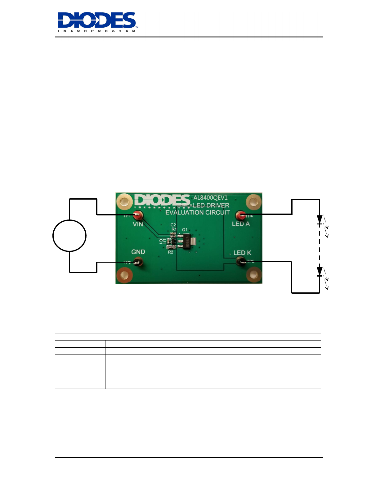
The AL8400QEV1, Figure 1, is a double sided evaluation board for the AL8400Q linear LED driver.
The evaluation board is preset to drive 150mA through the LED string, the maximum number of which
depends on their total forward voltage drop.
The operating voltage is between 4 and 18 volts, depending on the LED string to be driven. Higher
voltages for longer LED strings can be used by tapping off the board Vin from an intermediate point in
the LED string.
Note: The evaluation board does not have reverse supply protection.
The sense resistor R2 of 300mΩ sets the LEDs nominal current at 150mA.
Figure 1: AL8400QEV1 evaluation board and connection diagram
AL8400QEV1 Connection Point Definition
Name
Description
Vin
Positive supply voltage. 4 to 18V
GND
Supply Ground (0V)
LED A
LED A connects to the external LED string anode
LED K
LED K connects to the external LED string cathode
4-18VDC
LEDs
V
AL8400QEV1
September 2018 www.diodes.com
© Diodes Incorporated 2018
2
AL8400Q DEVICE DESCRIPTION
The AL8400Q is a 5-terminal adjustable Linear LED driver controller offering excellent temperature
stability and output handling capability. The AL8400Q simplifies the design of linear and isolated LED
drivers. With its low 0.2V FB pin, it controls the regulation of LED current with minimal power
dissipation when compared to traditional linear LED drivers. This makes it ideal for medium to high
current LED driving.
AL8400Q DEVICE FEATURES
Low reference voltage (VFB = 0.2V)
-40 to 125ºC temperature range
3% Reference voltage tolerance at
25°C
Low temperature drift
0.2V to 18V open-collector output
High power supply rejection
(>45dB at 300kHz)
DEVICE APPLICATIONS
Isolated offline LED converters
Linear LED driver
LED signs
Instrumentation illumination
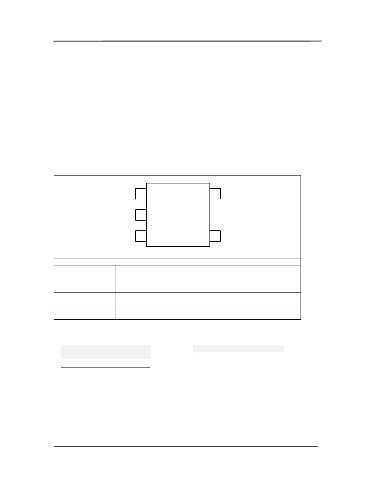
AL8400Q Device Packages, Pin and Definitions
AL8400Q
2
1
3 4
5
GND
E1
VCC FB
OUT
SOT353 pack
AL8400Q Device Pin Definition
Name
Pin No
Description
E1
1
Emitter connection. Connect to GND.
GND
2
Analog Ground: Ground return for reference and amplifier. Connect
to E1.
VCC
3
Supply Input. Connect a 0.47μF ceramic capacitor close to the device
from VCC to GND.
FB
4
Feedback Input. Regulates to 200mV nominal.
OUT
5
Output. Connect a capacitor close to device between OUT and GND.
ORDERING INFORMATION
EVALBOARD ORDER
NUMBER
AL8400QEV1
Please note: Evaluation boards are subject to
availability and qualified sales leads.
DEVICE ORDER NUMBER
AL8400QSE-7
 Loading...