

Diodes AL3353 EV1 User Manual
AL3353EV1 User Guide
High Performance Boost LED Controller
Parameter
Value
Input Voltage
20V ~ 36V
Output Power
48W
Output Current
800mA
Output Voltage
60V
Efficiency
>90 %
Dimension
70mm*50mm
RoHS Compliance
Yes
General Description
This demonstration board utilizes AL3353 to
build a cost effective solution for boost LED
driver.
AL3353 is a LED driver controller designed
for boost converters in a constant frequency
mode. It implements a peak current mode
control scheme and an internal transconductance amplifier to accurately control
the output current over a wide input and
load conditions.
Specifications
This user guide contains rich information for
the users. A bill of materials is included that
describes the parts used on this board. A
schematic and PCB layout is also included
along with measured system performance
characteristics and test waveforms. These
materials can be used as a reference
design for your products to improve your
product’s time to market.
Evaluation Board
Key Features
1. Wide Input Voltage Range: 20V to 36V
2. Constant Current Mode PWM Controller
3. PWM to Analog Dimming Mode
4. Audio Noise Free
5. Built-in Comprehensive Protections
a) Under Voltage Lock Out (UVLO)
b) Over Voltage Protection(OVP)
c) Over Current Protection(OCP)
d) Over Temperature Protection (OTP)
e) LED Open Protection
f) Output Short Protection
g) Diode & Inductor Short Protection
h) LED Cathode Short to GND Protection
6. Low system BOM cost
Applications
LCD TV
LCD Monitor
Flat Panel Display
AL3353 Page 1 of 9
Mar.2019
www.diodes.com
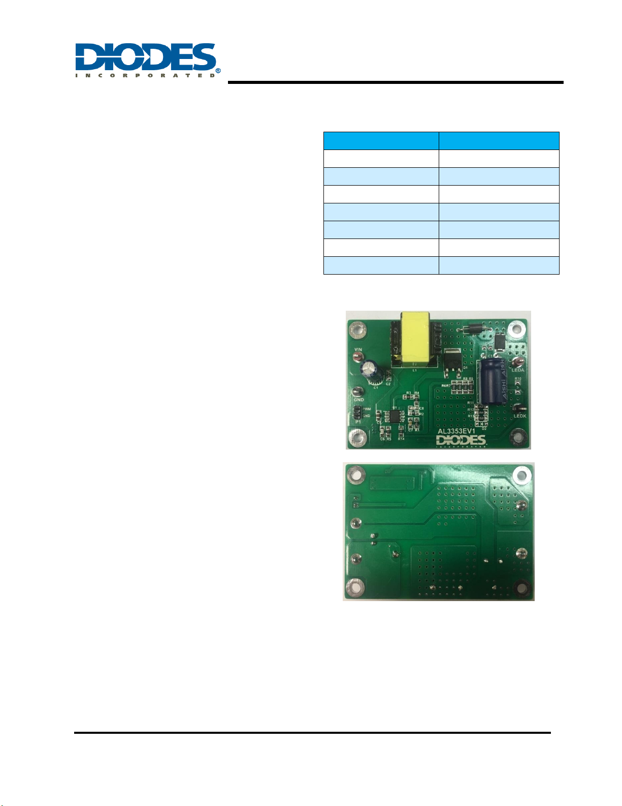
Connection Instructions:
DC Positive Input: White Test Point (VIN)
DC Negative Input: Black Test Point (GND)
PWM Signal Input: P1 (PWM)
GND Signal Input: P1 (GND)
Positive Output: Yellow Test Point (LEDA)
Negative Output: Black Test Point (LEDK)
Figure 1: Top View
Figure 2: Bottom View
AL3353EV1 User Guide
High Performance Boost LED Controller
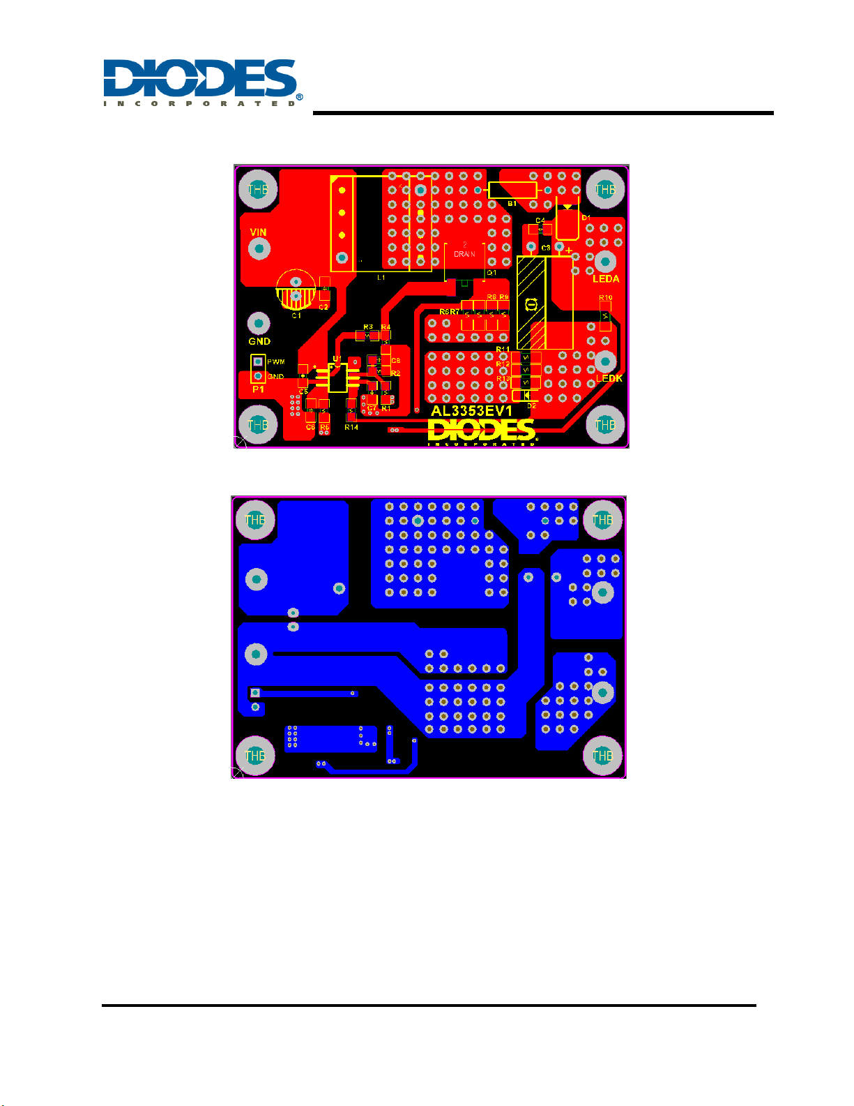
Board Layout
Figure 3: PCB Layout Top View
Figure 4: PCB Layout Bottom View
Quick Start Guide
1. Ensure that the power supply and the PWM signal are switched OFF or disconnected.
2. Connect the LED power supply to the test point “VIN” and “GND”.
3. Connect the LED PWM signal to the test point “PWM” and “GND”.
4. Connect the LED string anode to the test point “LEDA”.
5. Connect the LED string cathode to the test point “LEDK”.
6. Set the PWM signal and turn on the LED power supply. The LED string will light on and
output the preset current.
AL3353 Page 2 of 9
Mar.2019
www.diodes.com
AL3353EV1 User Guide
High Performance Boost LED Controller
Item
Quantity
Package
Description
B1
1
DIP
Ferrite Bead, 50Ω@100MHz
C1
1
DIP
Electrolytic Capacitor, 47uF, 50V, 6.3*11
C3
1
DIP
Electrolytic Capacitor, 100uF, 100V, 10*16
C5
1
0805
Ceramic Capacitor, 1uF, 50V, X7R, ±10%
C6
1
0805
Ceramic Capacitor, 100pF, 16V, X7R, ±10%
C7
1
0805
Ceramic Capacitor, 220nF, 16V, X7R, ±10%
C8
1
0805
Ceramic Capacitor, 470pF, 16V, X7R, ±10%
D1
1
PowerDI5
Schottky Diode, SDT5H100P5, 100V,1A
L1
1
EE1610
Inductor, 100uH, EE1610, 36Ts
Q1
1
TO252
MOSFET, DMT10H010LK3, N Channel, 100V, 8.8mΩ
R1
1
0805
SMD Film Resistor, 475kΩ, ±1%
R2
1
0805
SMD Film Resistor, 13kΩ, ±1%
R3
1
0805
SMD Film Resistor, 10Ω, ±1%
R4
1
0805
SMD Film Resistor, 10kΩ, ±1%
R5
1
0805
SMD Film Resistor, 0Ω, ±1%
R6, R7, R8, R9
4
1206
SMD Film Resistor, 0.4Ω, ±1%
R11, R12, R13
3
1206
SMD Film Resistor, 1.5Ω, ±1%
U1
1
SO-8
IC, AL3353
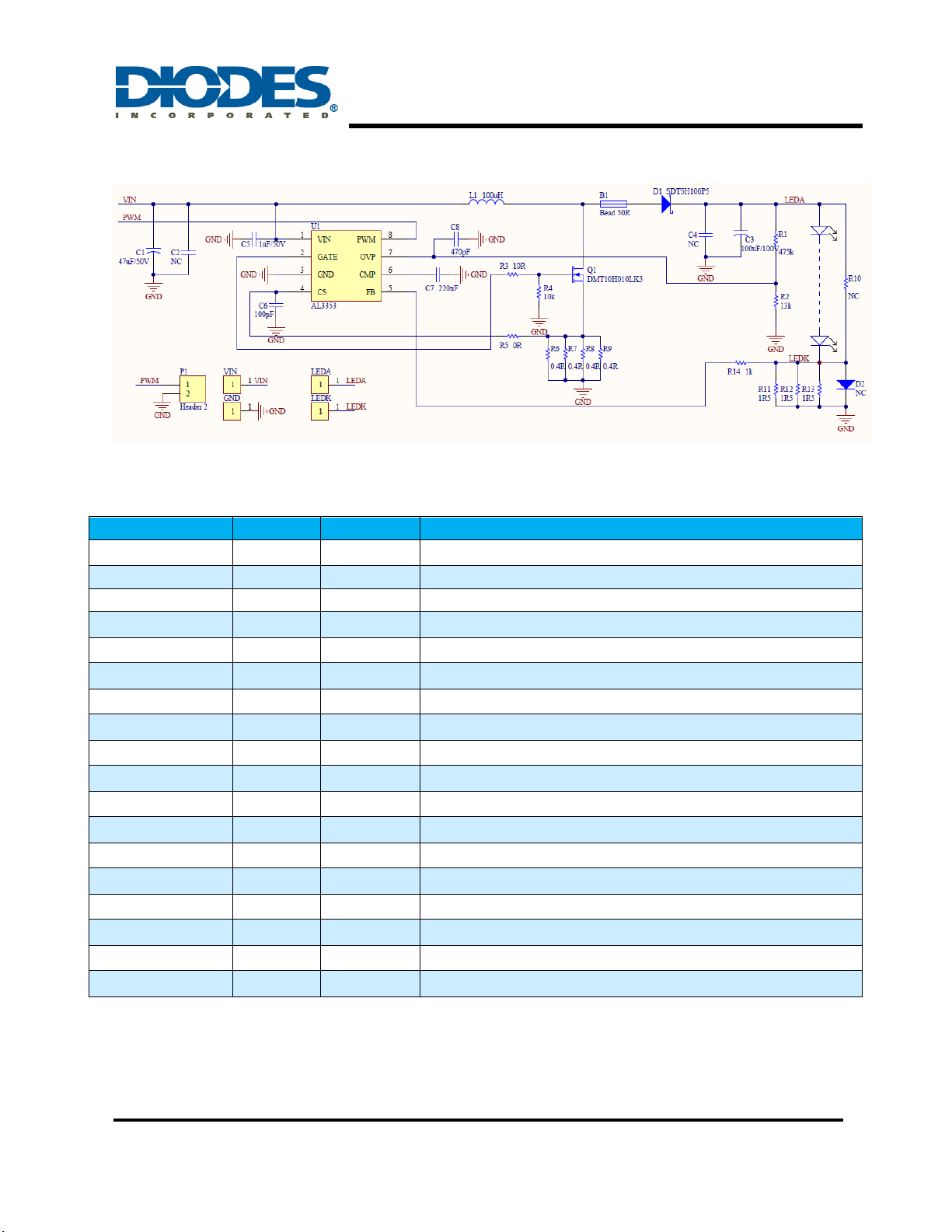
Schematic
Bill of Material
Figure 5: Schematic Circuit
AL3353 Page 3 of 9
Feb.2019
www.diodes.com
 Loading...