

Page 1
Owner’s Manual
Quantum Storage Heater
Models:
Boost Output
208/240V~
Rated Input
208/240V~
Rated Output for 8hr
Charge Period
# of Bricks
(3 Bricks per Package)
Installed Weight
kWh 10.9 kWh 15.4 kWh 19.3 kWh 23.1 kWh
IMPORTANT SAFETY INFORMATION: Always read this manual rst before attempting to install or use this
Heating System. For your safety, always comply with all warnings and safety instructions contained in this
manual to prevent personal injury or property damage.
To view the full line of Dimplex products, please visit www.dimplex.com
QSH-70 QSH-100 QSH-125 QSH-150
473/630W 660/880W 848/1130W 1035/1380W
1170/1560W 1665/2220W 2070/2760W 2478/3300W
700W 1000W 1250W 1500W
18 24 30 36
91 kg
(200 lbs)
115 kg
(254 lbs)
142 kg
(313 lbs)
165 kg
(364 lbs)
7212670100R04
Page 2

Table of Contents
Welcome & Congratulations ........................................................3
IMPORTANT INSTRUCTIONS ......................................................4
Quick Reference Guide ............................................................5
General Introduction ..............................................................5
The Benets of Quantum ..........................................................5
Choosing a Location ..............................................................5
Site Selection and Preparation ......................................................6
Installation Instructions ............................................................7
Electrical Connections ............................................................7
Building the Center Core ..........................................................8
Reassembly ....................................................................9
Operation ......................................................................10
Controls ......................................................................10
Control Functions ...............................................................10
Setting the Date and Time ........................................................11
Choosing and Setting a Timer Mode ................................................11
Boost. . . . . . . . . . . . . . . . . . . . . . . . . . . . . . . . . . . . . . . . . . . . . . . . . . . . . . . . . . . . . . . . . . . . . . . . . 12
Options .......................................................................13
Child Lock .....................................................................13
User Information ................................................................13
Service Menu ..................................................................13
Maintenance ...................................................................14
Warranty .....................................................................15
Quantum - Quick Set-Up Sheet and Settings Records ......................................16
Always use a qualied technician or service
agency to repair this system.
!
NOTE: Procedures and techniques that are
considered important enough to emphasize.
CAUTION: Procedures and techniques which,
if not carefully followed, will result in damage to
the equipment.
WARNING: Procedures and techniques which,
if not carefully followed, will expose the user to
the risk of re, serious injury, or death.
2 www.renewables.dimplex.com
Page 3
Welcome & Congratulations
Thank you and congratulations for purchasing a Quantum Storage Heating System from
Dimplex. Please use our convenient online registration page to record your model and
serial numbers for future reference at
www.dimplex.com/register
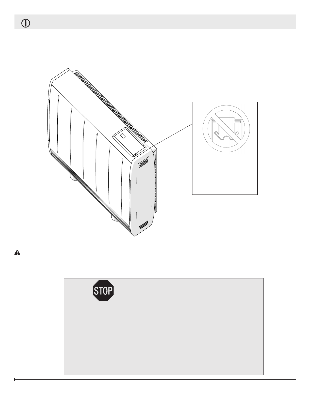
DO NOT COVER
Model:
Serial:
Series:
Please carefully read and save these instructions.
CAUTION: Read all instructions and warnings carefully before starting installation.
Failure to follow these instructions may result in a possible electric shock, re hazard
and will void the warranty.
NO NEED TO RETURN TO THE STORE
Questions with operation or assembly? Require Parts Information?
Product Under Manufacturer’s Warranty?
Contact us at: www.dimplex.com/customer_support
For Troubleshooting and Technical Support
OR Toll-Free 1-888-DIMPLEX (1-888-346-7539)
Monday to Friday 8:00 a.m. to 4:30 p.m. EST
In order to better serve you, please have your model and serial number
ready or register your product online before calling (See above)
3
Page 4

IMPORTANT INSTRUCTIONS
When using electrical appliances, basic precautions should always be followed to reduce the risk of re, electric
shock and injury to person, including the following:
1. Read all instructions before using this heater.
2. Heater and controls should be installed by a qualied contractor. Wiring procedures and connections should
be in accordance with the National Electric Code (CEC & NEC) and local codes.
3. A heater has hot and arcing or sparking parts inside. Do not use it in areas where gasoline, paint or ammable
liquids are used or stored.
4. This heater is hot when in use. To avoid burns, do not let bare skin touch hot surfaces. Keep combustible materials such as: furniture, pillows, bedding, papers, clothes and curtains away from heater.
5. To prevent a possible re, do not block air intakes or exhaust in any manner. Do not use on soft surfaces like a
bed where openings may become blocked.
6. Do not insert or allow foreign objects to enter any ventilation or exhaust opening as this may cause an electric
shock or re, or damage the heater.
7. Do not install these heaters against combustible, low density cellulose bre surfaces or vinyl wall paper.
8. Do not locate these heaters below any electrical convenience receptacles.
9. Quantum heater are not suitable for installation in bathrooms or areas of high humidity.
10. Check nameplate ratings to be sure the heater voltage is the same as the service supply.
11. HIGH TEMPERATURES: Keep electrical cords, furniture, draperies or any other blocking material away from
the heater. See Installation Section for specic distances.
12. The heater is very heavy and must be secured to a wall to ensure that it cannot move.
SAVE THESE INSTRUCTIONS
4 www.renewables.dimplex.com
Page 5
Quick Reference Guide
General Introduction
This storage heater heats its highly insulated storage core of dense ceramic material at preselected
times to meet the day’s heating requirements.
When heat is required throughout the day, the
heater releases its stored heat by a silent thermostatically controlled fan. The Dimplex control
system automatically stores more energy as it
gets colder, keeping you warm and comfortable no
matter the outdoor conditions. Additional boost elements are incorporated to ensure consistent comfort if the core ever runs low on energy.
The Benets of Quantum
Quantum is designed to be a responsive heating
system that meets your comfort requirements while
optimizing energy use. The heater releases heat in
two ways:
• A small amount of heat is dispersed by ‘natural’ convection and radiation from the heater
case.
• The vast majority of heat is released using the
built-in fan that pushes hot air out from the
heat outlet grille at the bottom of the product.
Minimizing the release of stored heat from the
outer casing means that more energy is available
when warmth is required. This makes more efcient use of the stored energy as you can ‘turn off’
the heater when you are out or do not need it.
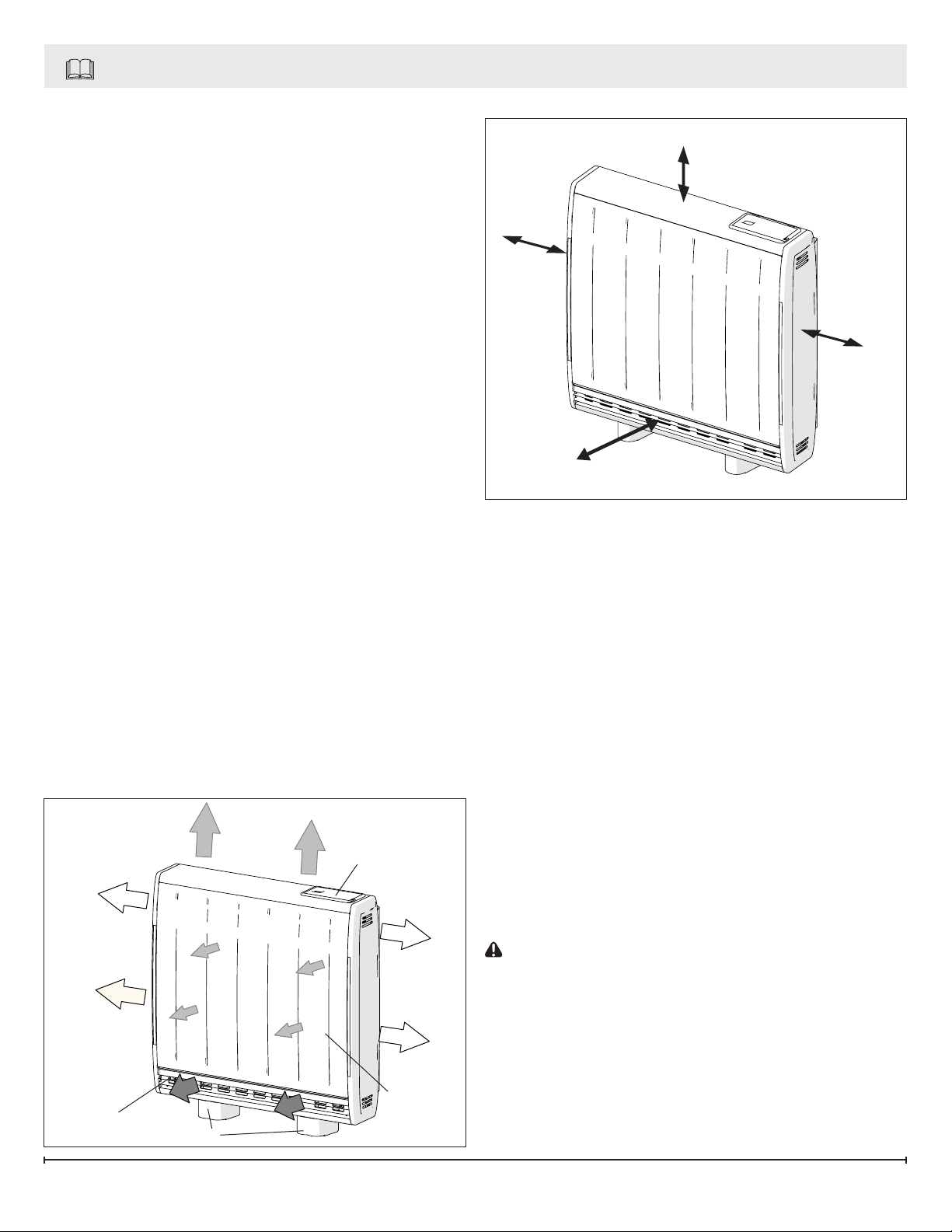
Figure 1
Controls
Figure 2
250 mm (9.8”)
100 mm
(3.9”)
100 mm
(3.9”)
300 mm (11.8”)
Choosing a Location
Compared with traditional storage heaters the
amount of energy released from the outer case
of the heater is signicantly reduced. This allows
more efcient running because the Quantum is
heating the room only when you want it to.
!
NOTE: Occasional clicking sounds during
operation are due to temperature changes in the
storage core.
When determining a location for the Quantum Storage Heater ensure that no objects are closer than
300 mm (11.8”) in front of the unit, 100 mm (3.9”)
on either side or 250 mm (9.8”) above the heater.
(Figure 2)
!
NOTE: The new material in the heater will produce a slight smell for the rst few days of operation.
Heat Outlet
Feet
Front
Panel
CAUTION: Rooms must be well ventilated and
your children, cages birds, or persons with respiratory complaints must not remain in close proximity
to the heater during the rst 48 hours of the startup period of each heater.
!
NOTE: During rst operation of the fan you may
notice a small amount of dust discharged from the
air outlet grille at the bottom of the product.
5
Page 6
Site Selection and Preparation
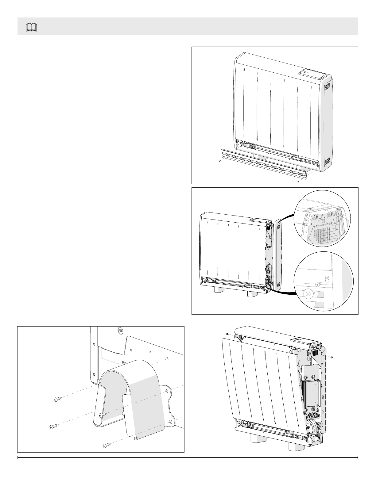
1. Place the heater at on the ground with arrows
printed on the base of the carton pointing
upwards. Open the carton at the bottom, slide
the heater out of the carton exposing the
feet and the hardware kit located within the
packaging on the right hand side. Remove the
feet and the hardware kit.
2. Secure the feet to the heater, using the screws
provided in the hardware kit.
!
NOTE: For models QSH-70 and QSH-100
two locations are possible for mounting each
foot. They are indicated by an “X” and “Y”
marking visible on the base of the heater.
3. Ensure the feet are secured at the location
holes marked with an “X”, see Figure 3.
4. Stand the heater on its feet before removing
the packaging.
5. Once the feet have been secured and the unit
has been turned upright, remove the grille from
the side of the unit. (Figure 4)
Figure 4
Figure 5
B
6. Remove the two screws located towards the
bottom at each end of the heater, which retain
the heater sides. (Figure 5A)
7. Push the end panels vertically upwards to
release each side from its securing points.
(Figure 5B)
8. Remove the two screws securing the front
panel, located at the upper sides of the heater,
and swing the upper edge of the front panel
forwards and unhook it from along the heater
base. (Figure 6)
Figure 3
A
Figure 6
6 www.renewables.dimplex.com
Page 7
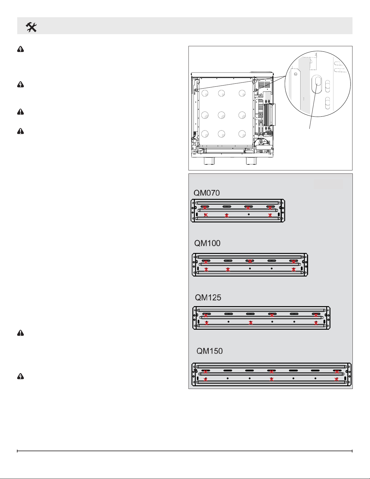
Installation Instructions
WARNING: This appliance is heavy. The oor
must be checked to ensure that it is capable of
bearing the weight of the unit up to 177 kg (390
lbs).
WARNING: Do not under any circumstances
attempt to move or reposition this heater without
seeking expert advice.
CAUTION: The heater must be securely xed to
a wall before operation.
CAUTION: Do not install the unit on carpet or
any other soft surface. If installing in a carpeted
area remove the carpet and underlay so that the
feet rest directly on the oor. Ensure that the unit is
level.
1. Place the heater in its nal position and mark
the xing holes through the location holes
visible through the back of the heater.
Mark the xing positions at the two extreme
ends of the heater with the heater pushed tight
against the wall.
Remove the wall bracket from the heater by
removing the two screws at each end of the
bracket. Place the heater to one side and
position the bracket against the wall aligning it
with the location marks.
2. Six screw locations, on the bracket, must be
selected for each model. Mark the positions for
the screw holes. Remove the bracket from the
wall, drill the holes and mount the bracket using
the appropriate hardware for that particular type
of wall.
3. Secure the heater to the bracket using the
screws previously removed.
CAUTION: Under no circumstances should
these screws be removed without rst removing all
bricks from the heater.
Figure 7
Mounting Holes
Figure 8
Electrical Connections
WARNING: The installation of this appliance
should be carried out by a competent electrician
and be in accordance with National Electrical
Codes (NEC) and local codes.
1. The heater is factory congured to operate with
one main power supply.
2. Storage/Fan Circuit:
• Ensure the black wire is connected to the
7
Page 8
Installation Instructions
terminal marked L1.
• Ensure the red wire is connected to the
terminal marked L2.
• The ground wire should be connected to the
terminal marked E or .
!
NOTE: For 208V installations the wiring must be
modied for the motor to operate correctly.
• 208V installations ONLY: Disconnect the blue
wire on T6 and connect it to T5.
3. The main power entry clamp and terminal block
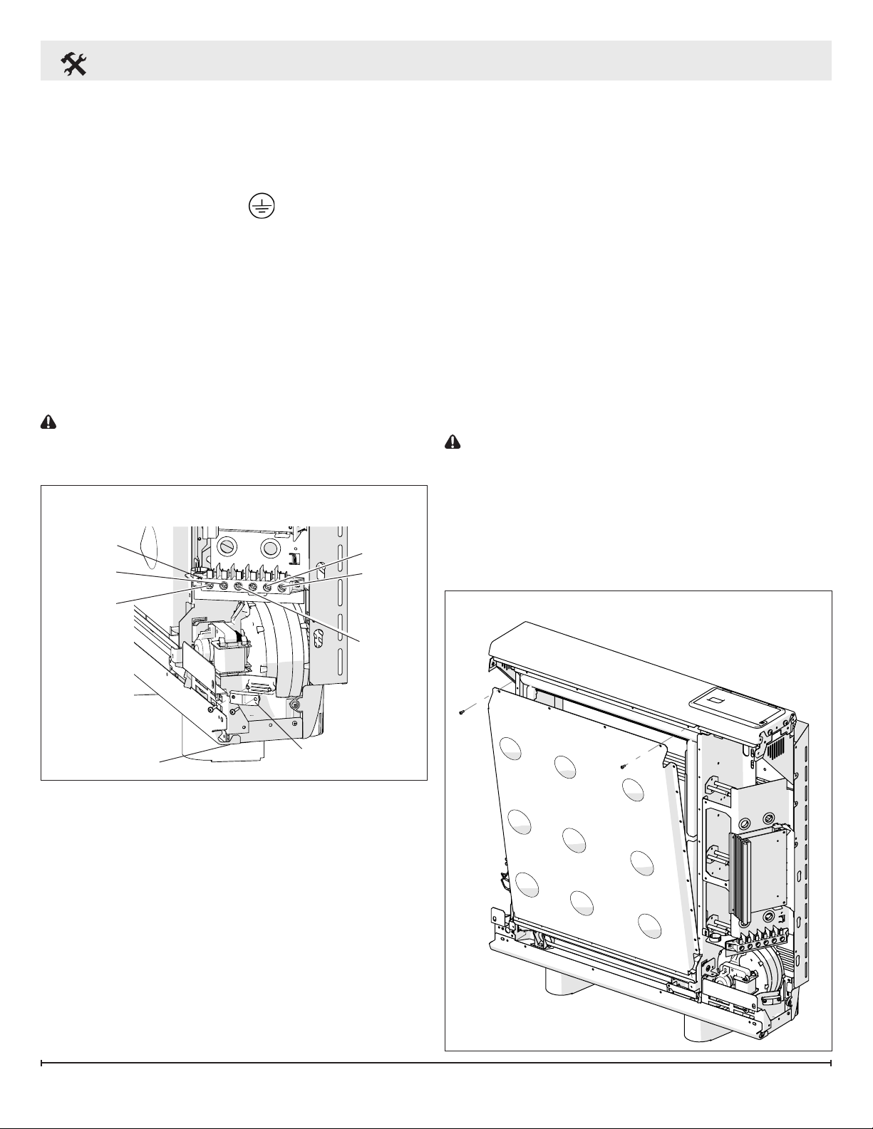
will be visible on the right hand side of the unit.
Insert the power cables through the opening at
the bottom of the heater and connect. (Figure
9)
CAUTION: Only heat resistant wiring should be
used, capable of withstanding temperatures up to
90°C (194°F).
Figure 9
208/240V Installations
Terminal
Block
L
2
T5
T6
Building the Center Core
1. Remove the inner panel to access the core of
the heater. Lay the inner panel carefully to one
side to ensure it is not damaged. (Figure 10)
2. Remove any internal packaging.
3. The bricks have several grooves on one
surface for locating around the elements. The
two slots through the centre of the brick create
the air passages within the core.
4. Position the rst brick of the bottom row to the
right rmly pressed against the side insulation
with the element grooves facing upwards and
tting neatly around the element. Angle the
element upward to t the brick and the air
passages line up with the holes in the base
insulation.
CAUTION: Do not disconnect the element
terminals
5. Fit the remaining bricks in the bottom row being
careful not to damage or dislodge the element.
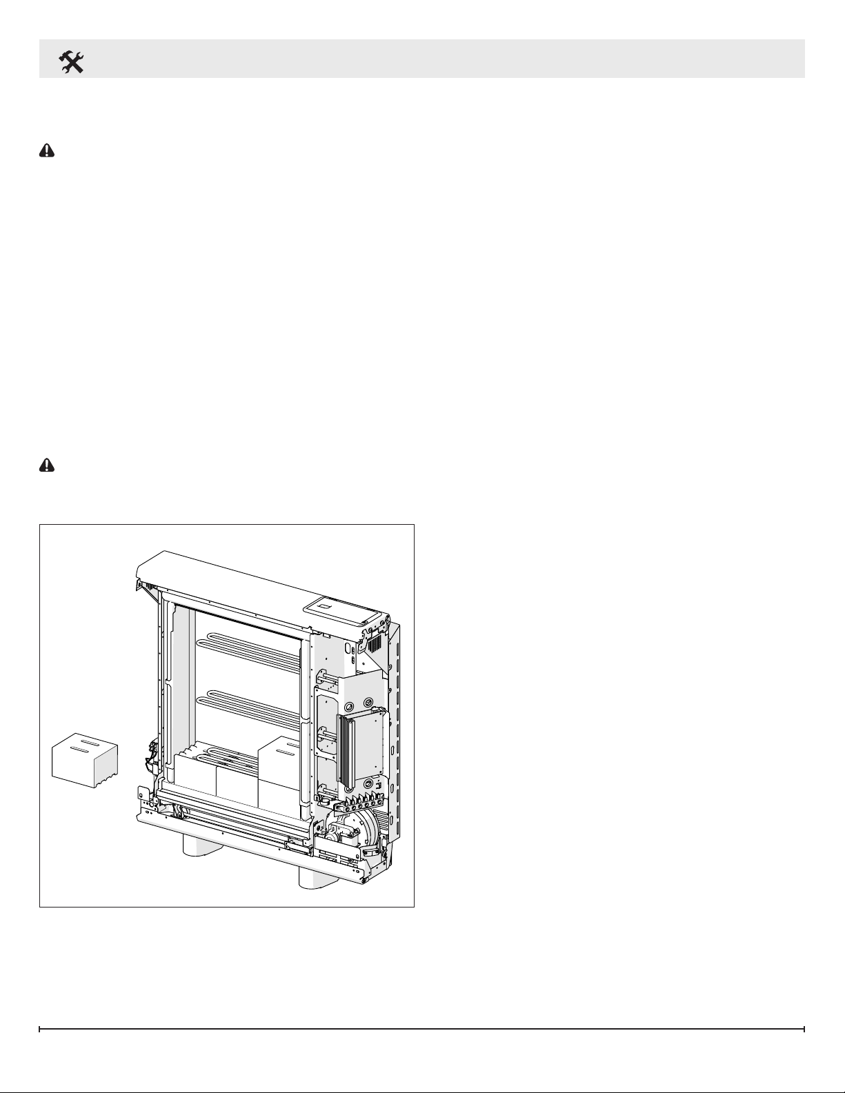
6. Position the second row of bricks so that they
are facing down and the element sits within the
grooves. (Figure 11)
L
1
Wire Entrance
Figure 10
G
Cable Clamp
8 www.renewables.dimplex.com
Page 9
Installation Instructions
7. The third row of brick is positioned in a manner
similar to the rst row.
CAUTION: Be careful not to damage or
dislodge the element.
8. Repeat the pattern for the remaining rows.
9. Check that all the bricks are secure and evenly
located.
10. Close the core by replacing the inner panel
complete with insulation.
11. Ensure the bottom edge is located inside the
chassis and that the screws are tightly secured
at each edge.
!
NOTE: Double check all wiring connections
are secure and any excess cable is restrained
and cannot come in contact with any of the
heater casing. Under no circumstances should
any excess cable be pushed inside or behind the
heater.
CAUTION: Once installed do not attempt to
reposition the heater without rst unloading the
bricks.
Reassembly
1. Replace all the panels of the outer casing
reverse steps 5-8 of Site Selection and
Preparation Section.
2. Ensure all of the hardware has been tightened.
3. Clean the outlet grille and adjacent surfaces
after the rst operation as some dust may be
produced when the heater is rst used.
In cases where unauthorized persons may tamper with the control settings it is possible to set a
tamper-proof feature at the time of installation, by
pressing and holding the Back button and the Selector Dial simultaneously for three seconds, ‘Child
Lock’ will appear on the screen, repeat to reverse.
See the Operating Instructions for further details.
Figure 11
9
Page 10
Operation
CAUTION: During the initial operation some
odor may be noticed due to the newness of materials used in manufacturing. This is normal and will
disappear after a short period of use. It is however
advisable to keep the room well ventilated. Rooms
must be well ventilated and young children, caged
birds, or persons with respiratory complaints must
not remain in close proximity to the heater during
the rst 48 hours of the commissioning period. This
must be done for each heater (staggered over a
few days).
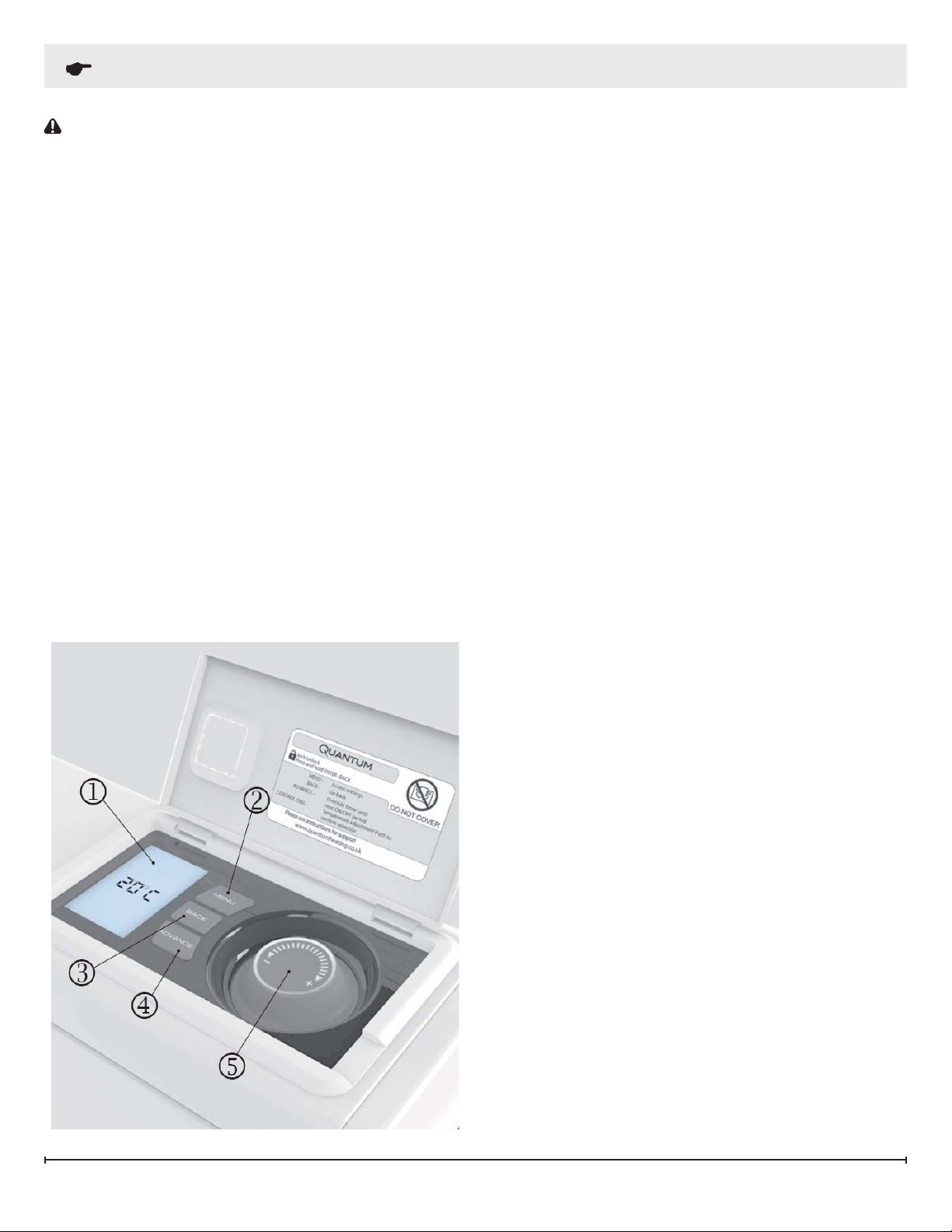
Controls
The user controls are located on the top right of
the heater. The heater is tted with an adjustable
electronic temperature controller and three buttons.
1. Display Screen
2. “Menu” Button
3. “Back” Button
4. “Advance” Button
5. “Selector Dial”
The minimum room temperature setting is 7°C
(45°F) and may be used for protection against
frost. The maximum temperature setting available
is 30°C (86°F).
A temperature of approximately 20°C (68°F) represents a normal room temperature.
It is normal for the fan to stop running for periods
of time. This happens because the room temperature is at or above the temperature set on the
control and the room does not need any more heat
at that time.
Control Functions
The heater controls can easily be adjusted by
using a combination of the three buttons and the
selector dial, which can be rotated and pressed.
1. DISPLAY SCREEN shows the options available at each stage of the adjustment. COM-
FORT ON/OFF illustrates the part of the time
function that is currently running.
Comfort On – will control the room to the
set temperature.
Comfort Off - will control the room to the
setback temperature.
Boost Mode - includes an auxiliary boost
element to ensure consistent comfort if the
core ever runs low on energy.
2. MENU displays the options available;
Date/Time - Setting current date/time.
Timer Mode - Setting the timer to your indi-
vidual requirements.
Boost – Enables the auxiliary boost ele-
ment to work automatically. Associated
timer can be set to operate heater for 1 – 4
hours at a time.
Options - Temperature formats, ‘Daylight
Saving’ settings, and Setback settings.
3. BACK shows previous programming stage.
4. ADVANCE button on the User Interface is
used to skip from the current Comfort mode
to the next – turning the heater from OFF to
ON or vice versa.
10 www.renewables.dimplex.com
Page 11
Operation
5. SELECTOR DIAL can be turned clockwise
and counter clockwise, and enables the required room temperature to be adjusted. The
screen color changes for warmer and cooler
settings, showing deep blue through to bright
red.
To check what setting the heater is currently
using press the selector dial once and the
timer mode will be displayed e.g. ‘Work
Week’.
!
NOTE: The selector dial is also used in combination with the menu button to select and conrm
your settings.
!
NOTE: When the heater is initially installed, a
Warning Message may appear. This means the
real time clock has not been initialized. This can be
set by pressing the Menu button and following the
above steps to set the time.
Choosing and Setting a Timer Mode
Your Quantum controller comes pre-programmed
with a set of operating periods. There are four options available - three preset (Work Week, Home
All Day and Holiday), and one user setup (Manual).
The preset options include days and times (outlined below) that are pre-programmed to release
heat based on temperature set points.
The heater is programmed so that the amount of
heat that is stored is adjusted depending on the
time of the year, i.e. in January the heater will be
using the full capacity of the storage capabilities
and in April only a portion will be used. Also the
settings for the months May - August the storage
ability is disabled, so if the controller calls for heat
the supplemental element will provide it and no
heat will be stored.
Setting the Date and Time
Your Quantum controller incorporates a real time
clock with a calendar function. The time clock has
a battery back up that will keep the clock running in
the event of a power outage.
To adjust the time or date follow the steps below.
!
NOTE: The display screen will return to standard display after a period of 20 seconds of inactivity.
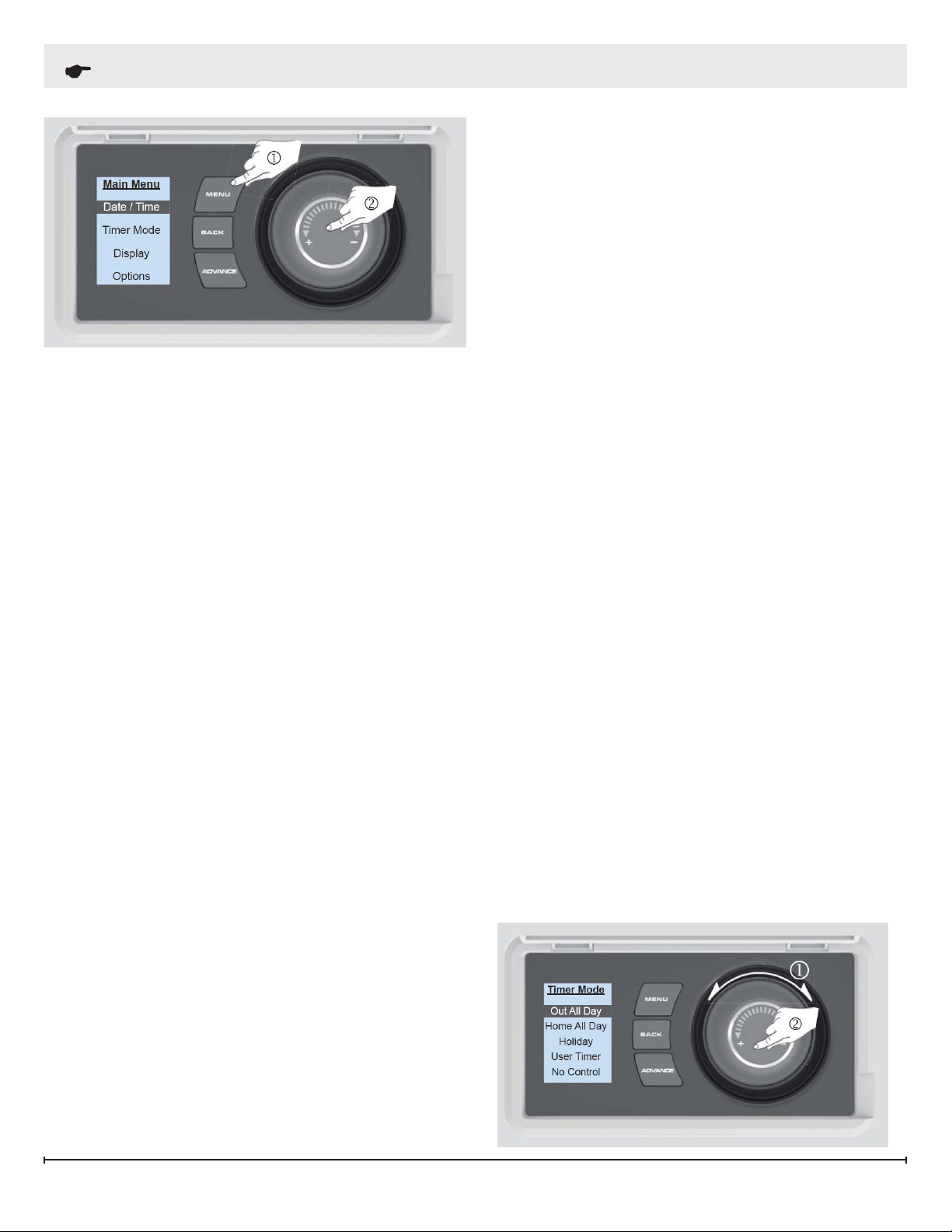
• Press the Menu Button (1).
• Select Date/ Time by pressing the control dial
(2).
• Rotate the dial to select the correct ‘day’ and
press the centre of the dial to select.
• Rotate the dial to select the correct ‘Day of
the Month’ and press the centre of the dial
to select. Repeat this operation until date and
time have been sent and the display returns to
the Main Menu.
!
NOTE: The Work Week, Home all Day and
Manual timer modes will use the comfort temperature during the “On” times and a setback temperature during the “Off” times. How to set the setback
temperature can be found under the description of the
“Options” Menu in this document.
1. Work Week (pre-programmed) - Has the following preset times, which can be altered if
desired;
Monday – Friday: On 6:00 am until 8:00 am
11
Page 12
Operation
Monday – Friday: On 4:00 pm until 10:00 pm
Saturday – Sunday: On 6:00 am until 10:00 pm
2. Home all Day (pre-programmed) - – Has the
following preset times Monday to Sunday,
which can be altered if desired;
6:00 am until 10:00 pm
3. Holiday (pre-programmed for 13 days at 10°C
(50°F)) – Set the number of days required
(from 1 to 160) and the temperature required,
this can be as low as 7°C (45°F) and as high
as 30°C (86°F).
4. Manual - In Manual mode the heater comes
defaulted to only operate with the supplemental
element. The user then has the ability to set
the Comfort On settings, including the days,
times and set points that will allow for the
heater to release heat.
To choose a Timer Mode press Menu and rotate
the dial to select ‘Timer Mode’.
Select the mode required, again by rotating and
pressing the dial. For options Work Week, Home
All Day and Manual, three choices are available -
Select, Preview and Modify.
Select - Choose this timer option.
Preview - View the times currently set.
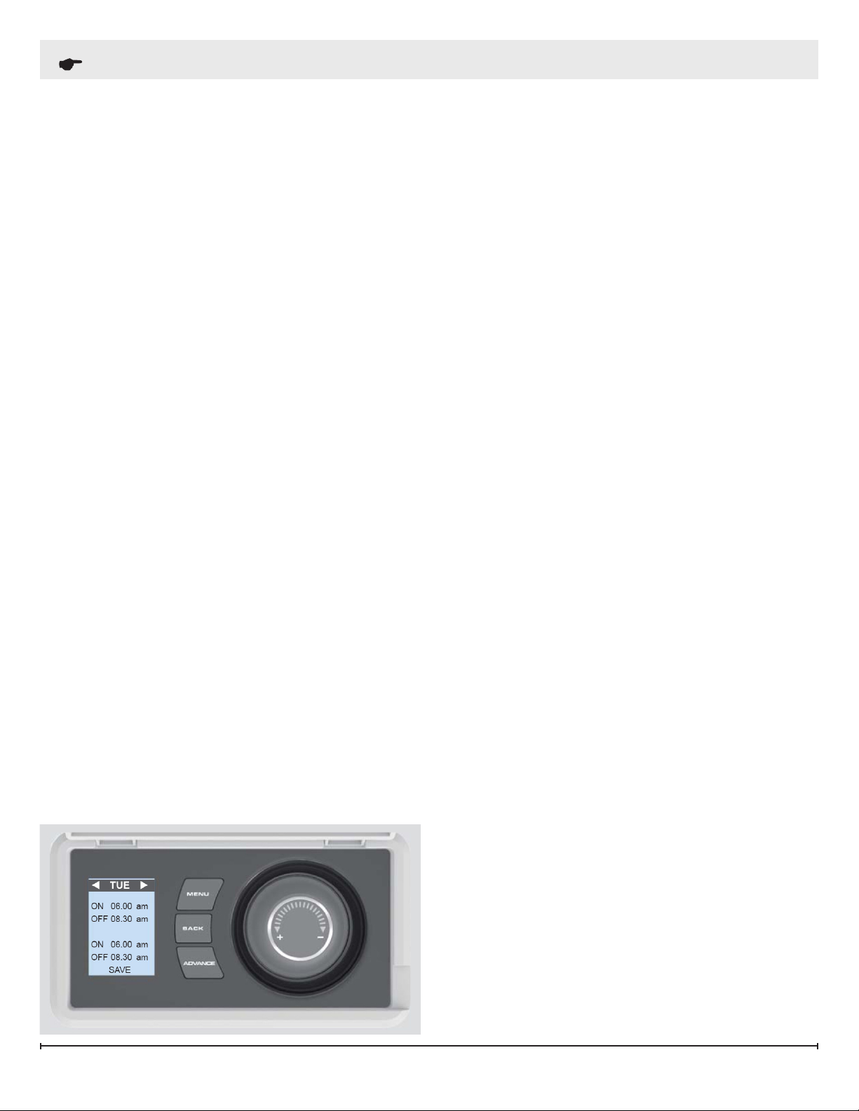
Modify - Change the times used.
by again choosing Modify, selecting the day with
the correct settings and either choosing Copy next
or Copy all. If preferred each day can be modied
individually and saved. If is also possible to Clear
each day or Clear all days. Options are:
Save - Save times for one day.
Copy next - Copy times to following day.
Copy all - Copy times for all several days.
Clear - Reset to factory preset.
Clear all - Reset to factory for all seven
days.
!
NOTE: The unit defaults to Save. To access the
other options turn the dial.
!
NOTE: There are four time options across 4
screens.
In Holiday modes the number of days that the
room will be unoccupied for can be adjusted together with the required room temperature.
!
NOTE: Using this option could lead to high energy consumption. It is therefore recommended to
use this function only for short periods.
!
NOTE: The desired room temperature can be
selected by rotating the dial clockwise and counter
clockwise.
Boost
When Modify is chosen, select and change each
option by rotating and pressing the dial. When a
day is complete select Save to update it.
Once the rst day has been set up it is possible to
copy these settings to successive days or all days
12 www.renewables.dimplex.com
The Boost menu allows you to choose the mode
for the auxiliary boost element designed to come
on if the storage core runs low on energy, options
include:
No Boost – Choose this option if you never
want the auxiliary boost element to turn on.
1-4 hours – Timer can be set to enable the
heater for a specied period of time - 1 to 4
hours.
Auto Boost – Enables the auxiliary boost element to come on automatically as required
providing the highest comfort level.
Page 13

Operation
Options
The Options Menu enables you to choose time and
temperature formats that suit your preferences.
These are:
DST Rule (Daylight Saving Setting) - None, UK/
Ireland, Canada & US
Temp Units - °C or °F
Setback Temp – Setback Temperature denes
the Comfort OFF temperature by the number
of degrees below the Comfort ON temperature. It ranges from 0°C (0°F) to 5°C (9°F).
It is highly recommended that a setback of
2°C (4°F) or less is used to reduce the time
the heater takes to bring the room back to its
Comfort On temperature. For example: If Setback temperature is 2°C and the comfort ON
temperature is set to 21°C, when the timer
mode switches to comfort OFF the heater will
regulate the room temperature at 19°C.
Child Lock
To lock the controls press back and the selector
dial together for 5 seconds. Child Lock will appear
at the bottom of the screen. To unlock the control
repeat the action of pressing back and selector
dial for 3 seconds.
!
NOTE: The controls cannot be adjusted when
the child lock is active.
User Information
Service Menu
CAUTION: Changing the settings in the Ser-
vice Menu should ONLY be done by a SERVICE
TECHNICIAN as changes may affect the preferred
operation of the unit.
Press and hold the Menu, Back AND Selector dial
for 5 seconds to display the Service Menu, ve options are available:
1. Congure - has three options within it:
a. Initial Charge – Determines whether an
initial charge of 0% or 100% is needed.
b. Fan Speed - Adjustment of fan speed
between 75% and 100% mainly used to
reduce noise control.
!
NOTE: A lower maximum fan speed re-
sults in a lower maximum heater output.
c. Calibrate RTC (Real Time Clock) - Re-
boots the heater. The screen will light up
with no display during this process.
2. Appliance ID - Indicates you heaters unique
identication number.
3. Charge Time - Sets the standalone charge
time. When not connected to the Quantum
hub, this setting will be the core charging
time.
4. Heater Size - Displays the capacity of the
heater. The capacity of the heater can be
found on the rating label on the outer shell of
the heater.
Press and hold the selector dial for 5 seconds to
display the user information menu, three choices
are available:
SP Range - Adjustment of the temperature
range available
Factory - Returns all settings to the factory
presets – Yes or No.
Extra Charge - Adjustment to increase the
amount of energy stored
!
NOTE: This setting should only be changed if
found to be incorrect.
13
Page 14

Maintenance
Cleaning
WARNING: Disconnect circuit power before at-
tempting any maintenance or cleaning to reduce
the risk of electric shock or damage to persons.
To maintain the external appearance of the heater
it needs to only to wiped over occasionally with a
dry cloth. During the summer months, or at other
times when the appliance is not in use and is
completely cold, the opportunity should be taken to
wipe over with a damp cloth. Do not use abrasive
cleaning powers or furniture polish.
Discoloration of wall nished can sometimes occur immediately above a heater due to the properties of some paints and decorating materials or
the presence of environmental impurities in the air
such as soot or incense generated from the burning of candles, etc.)
14 www.renewables.dimplex.com
Page 15

Warranty
Products to which this limited warranty applies
This limited warranty applies to the following models of your newly purchased Dimplex Quantum Storage Heater. This limited warranty applies only to
purchases made in any province of Canada except for Yukon Territory, Nunavut, or Northwest Territories or in any of the 50 States of the USA (and the
District of Columbia) except for Hawaii and Alaska. This limited warranty applies to the original purchaser of the product only and is not transferable.
Products excluded from this limited warranty
Products purchased in Yukon Territory, Nunavut, Northwest Territories, Hawaii, or Alaska are not covered by this limited warranty. Products purchased
in these States, provinces, or territories are sold AS IS without warranty or condition of any kind (including, without limitation, any implied warranties or
conditions of merchantability or tness for a particular purpose) and the entire risk of as to the quality and performance of the products is with the purchaser,
and in the event of a defect the purchaser assumes the entire cost of all necessary servicing or repair.
What this limited warranty covers and for how long
Products covered by this limited warranty have been tested and inspected prior to shipment and, subject to the provisions of this warranty, Dimplex warrants
such products to be free from defects in material and workmanship for a period of 5 years from the date of the rst purchase of such product.
The limited 5 year warranty period also applies to any implied warranties that may exist under applicable law. Some jurisdictions do not allow limitations on
how long an implied warranty lasts, so the above limitation may not apply to the purchaser.
What this limited warranty does not cover
This limited warranty does not apply to products that have been repaired (except by Dimplex or its authorized service representatives) or otherwise altered.
This limited warranty does further not apply to defects resulting from misuse, abuse, accident, neglect, incorrect installation, improper maintenance or
handling, or operation with an incorrect power source.
What to do when your unit ceases to operate as described in this manual
Defects must be brought to the attention of Dimplex Technical Service by contacting Dimplex at 1-888-346-7539, or 1367 Industrial Road, Cambridge
Ontario, Canada N1R 7G8. Please have proof of purchase, catalogue/model and serial numbers available when calling. Limited warranty service requires
a proof of purchase of the product.
What Dimplex will do in the event of a defect
In the event a product or part covered by this limited warranty is proven to be defective in material or workmanship during the 5 year limited warranty period
you have the following rights:
• Dimplex will in its sole discretion replace such defective part(s) without charge, or if part replacement proves not to be commercially practicable or
cannot be timely made, Dimplex may, in lieu of replacing part(s) choose to replace the unit.
• This limited warranty does not entitle the purchaser to on-site or in-home services. On-site or in-home services may be performed at the purchaser’s
specic request and expense at Dimplex’s then-current rates for such services.
• The purchaser is responsible for removal and transportation of such product or part (and any repaired or replacement product or part) to and from the
authorized dealer’s or service agent’s place of business.
• Dimplex will not be responsible for, and the limited warranty services shall not include, any expense incurred for installation or removal of the product or
part (or any replacement product or part) or any labour or transportation costs. Such costs shall be the purchaser’s responsibility.
What Dimplex and its dealers and service agents are also not responsible for:
IN NO EVENT WILL DIMPLEX, OR ITS DIRECTORS, OFFICERS, OR AGENTS, BE LIABLE TO THE PURCHASER OR ANY THIRD PARTY, WHETHER
IN CONTRACT, IN TORT, OR ON ANY OTHER BASIS, FOR ANY INDIRECT, SPECIAL, PUNITIVE, EXEMPLARY, CONSEQUENTIAL, OR INCIDENTAL
LOSS, COST, OR DAMAGE ARISING OUT OF OR IN CONNECTION WITH THE SALE, MAINTENANCE, USE, OR INABILITY TO USE THE PRODUCT,
EVEN IF DIMPLEX OR ITS DIRECTORS, OFFICERS, OR AGENTS HAVE BEEN ADVISED OF THE POSSIBILITY OF SUCH LOSSES, COSTS OR
DAMAGES, OR IF SUCH LOSSES, COSTS, OR DAMAGES ARE FORESEEABLE. IN NO EVENT WILL DIMPLEX, OR ITS OFFICERS, DIRECTORS, OR
AGENTS BE LIABLE FOR ANY DIRECT LOSSES, COSTS, OR DAMAGES THAT EXCEED THE PURCHASE PRICE OF THE PRODUCT.
SOME JURISDICTIONS DO NOT ALLOW THE EXCLUSION OR LIMITATION OF INCIDENTAL OR CONSEQUENTIAL DAMAGES, SO THE ABOVE
LIMITATION OR EXCLUSION MAY NOT APPLY TO THE PURCHASER.
How State and Provincial law apply
This limited warranty gives you specic legal rights, and you may also have other rights which vary from jurisdiction to jurisdiction. The
provisions of the United Nations Convention on Contracts for the Sale of Goods shall not apply to this limited warranty or the sale of products
covered by this limited warranty.
15
Page 16

Customer Name Installer Name
Address Installer Phone #
Quantum - Quick Set-Up Sheet and Settings Records
General Settings
MENU button displays < Date/Time - Timer Mode - Option >
OPTIONS AVAILABLE SETTINGS RECOMMENDATIONS
• Select Date /Time by pressing the selector
dial
• Rotate the dial to select the correct day and
DATE / TIME
CHOOSING
AND
SETTING A
TIMER MODE
press the centre of the dial to select
• Rotate the dial to select the correct day of
the month and press the centre of the dial to
select
• Repeat until DATE and TIME have been set
and the Display returns to the Main Menu
• Work Week – if you typically work 5 days a
week during the day
• Home all Day – has pre-set times Monday to
Sunday which can be altered if desired
• Holiday – pre-programmed for 13 days at
10°C/50°F – set the number of days (from
1 to 160) and temperature required (from
7°C/45°F to 30°C/86°F)
• Manual – Four time slots are available and
can be customized for each day of the week,
set “comfort on” for at least 2 hours to take
some off-peak charge
Write down Date &
Time in next box
Work Week
Or
Home all Day
TECHNICIAN
TO INPUT
□
Work Week
□
Home
□
Holiday
□
Manual
BOOST
OPTIONS
• No Boost
• 1-4 hours
• Auto Boost
• DTS Rule – Daylight Saving Setting
• TEMP Units - °C or °F
• Setback temperature – Comfort OFF temperature
• No Boost - (lowest
operating cost)
• Auto Boost (highest comfort
level)
• Canada & US
• °C or °F
• No more than a
2°C setback is
recommended for
living areas
□
No Boost
□
1 hour
□
2 hours
□
3 hours
□
4 hours
□
Auto Boost
□ Canada
□ °C □ °F
_______°C
Page 17

Technical Service Menu
Press and hold the MENU, BACK buttons and SELECTOR dial (at the same time) for 5 seconds
to display the Service Menu
OPTIONS AVAILABLE SETTINGS RECOMMENDATIONS
CONFIGURE
Initial Charge (determines
whether an initial Charge
of 0% or 100% is needed)
Fan Speed 100% ______%
• 0% during summer (Recommended)
• 100% during heating season
Calibrate RTC Select Yes or No
Letters seen at the bottom
APPLIANCE ID
are the heater unique identi-
Please Enter →
cation numbers
Typically 23:00 – 07:00
Nova Scotia 23:00 – 07:00
Ontario 19:00 – 07:00
Please Enter →
CHARGE TIME
HEATER SIZE
Stand Alone charge time
(Utility Off-Peak period)
Displays the type of the
heater
User Information Menu
Press and hold the MENU and SELECTOR dial (at the same time) for 5 seconds to display the
User Information - and 3 Options will be displayed
TECHNICIAN
TO CHECK
□ 0%
□ 100%
□ Yes
□ No
OPTIONS AVAILABLE SETTINGS RECOMMENDATIONS
SP RANGE Temperature range Default is 7°C - 30°C
FACTORY Factory reset
EXTRA
CHARGE
Dimplex North America Limited
1367 Industrial Road
Cambridge ON
Canada N1R 7G8
Adjustment to increase the
amount of energy stored
Ignore, unless you want to reset to
factory settings
TECHNICIAN
TO INPUT
Max ______
Min ______
□ None
© 2015 Dimplex North America Limited
 Loading...