

Dimplex PH 075, PH 200, PH 075T, PH 125T, PH 150T Installation And Operating Instructions Manual
...Page 1
Installation and Operating Instructions
INVAUKP572 Issue 0
Panel Heaters
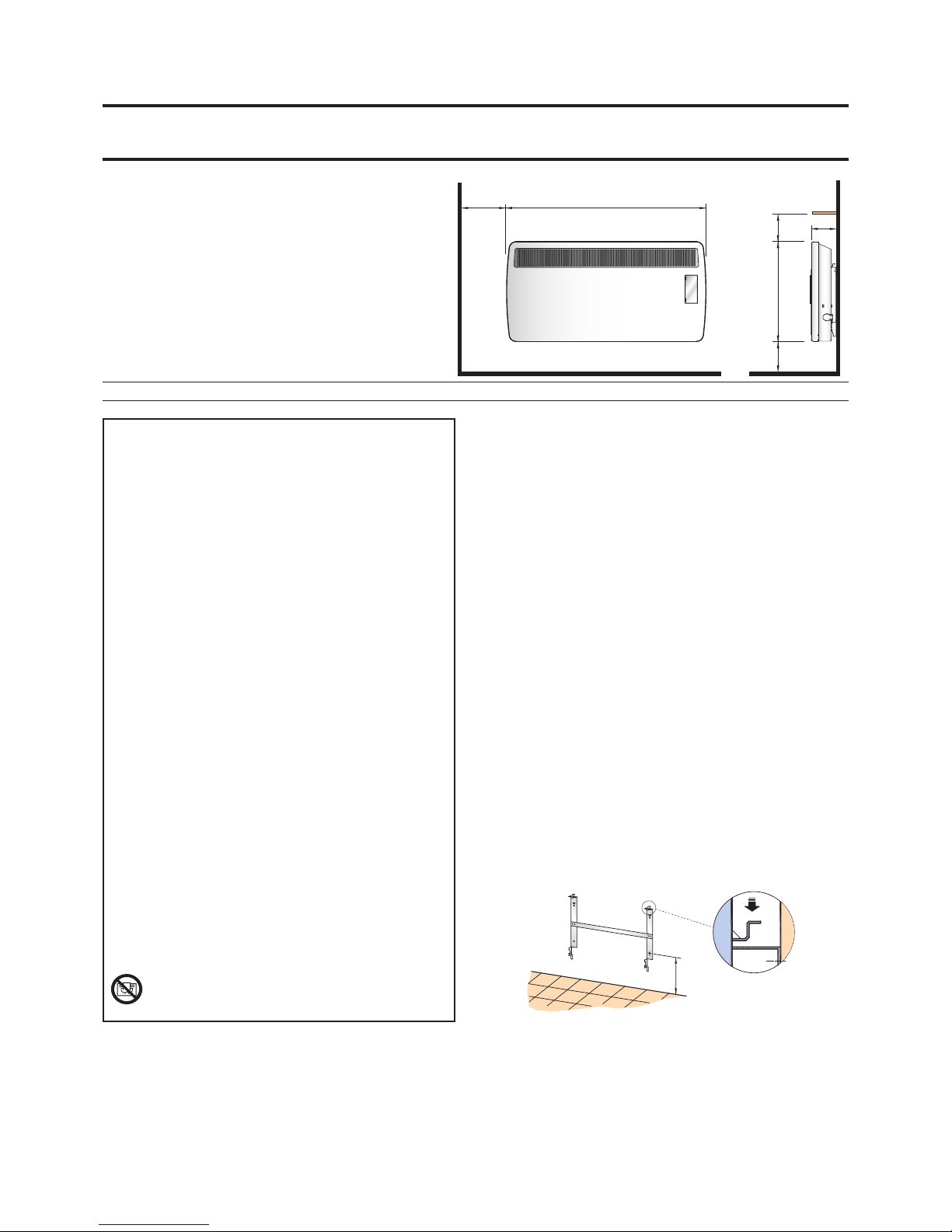
Dimensions
(millimetres)
Fig. 1
Fig. 2
Model(s) Watts A B
PH 075 750 620 108
PH 125 1250 688 108
PH 150 1500 688 108
PH 200 2000 860 108
PH 075T 750 620 108
PH 125T 1250 688 108
PH 150T 1500 688 108
PH 200T 2000 860 108
IMPORTANT : THESE INSTRUCTIONS SHOULD BE READ CAREFULLY AND RETAINED FOR FUTURE REFERENCE
Important Safety Advice
When using electrical appliances, basic precautions should always
be followed to reduce the risk of re, electrical shock, and injury
to persons, including the following:
IMPORTANT – The wall brackets supplied with the appliance must
be used.
IMPORTANT – If the heater is installed in a room containing a bath
or shower, it must be so installed that switches and other controls
cannot be touched by a person using a bath or shower.
Do not use outdoors.
Do not locate the heater immediately below a xed socket outlet
or connection box.
Do not cover the heater. Do not place material or garments on
the heater, or obstruct the air circulation around the heater, for
instance by curtains or pushing furniture up against the heater,
as this could cause overheating and a re risk.
NEVER cover or obstruct in any way the heat outlet slots at the top
of the heater or the air inlet slots in the base of the heater.
WAR NING – THE SU RFACE S OF THIS H EATER CA N BE HOT.
Momentary contact with any part of the heater should not cause
injury. However, aged or inrm persons or young children should
not be left unsupervised in the vicinity of the heater unless a
suitable guard is tted.
This appliance is not intended for use by children or other persons
without assistance or supervision if their physical, sensory or
mental capabilities prevent them from using it safely. Children
should be supervised to ensure that they do not play with the
appliance.
Note that due care and consideration must be taken when using
this heater in series with a thermal control, a program controller, a
timer or any other device that switches on the heat automatically,
since a re risk exists when the heater is accidentally covered or
displaced.
If the s uppl y cord i s dama ged it must b e repl aced b y the
manufacturer or service agent or a similarly qualied person in
order to avoid a hazard.
WARNING: IN ORDER TO AVOID OVERHEATING, DO NOT
COVER THE HEATER.
Electrical
WARNING – THIS APPLIANCE MUST BE EARTHED
The electrical installation must be carried out by a competent electrician,
and be in strict accordance with the current I.E.E. regulations for Electrical
Equipment in Buildings.
The heater is tted with a length of exible cable type H05VV-F size 3 x
1.0mm2 on 0.75kW - 2.0kW models and size 3 x 1.5mm2 on 3.0kW models,
for connection to the xed wiring of the premises through a suitable
connection box positioned adjacent to the heater.
The supply circuit to the heater must incorporate a double pole isolating
switch having a contact separation of at least 3mm.
Supplementary Earth Bonding
Should Equipotential Earth Bonding be required the earthing conductor
in the supply cord is deemed to provide the supplementary bonding
connection (see the 17th Edition of the I.E.E. Wiring Regulations).
General
The Panel heater is designed for wall mounting on the wall brackets
supplied. It should only be operated when in the upright position as
shown.
All models are splash proof to IP24 standard.
PH.... T models are tted with a 24 hour programme timer.
Before connecting the heater check that the supply voltage is the same
as that stated on the heater.
Wall Mounting
IMPORTANT – The wall brackets supplied with the appliance must be
used. The heater should be positioned observing the minimum clearances
stated around the heater - see Fig. 1.
DO NOT locate the heater immediately below a xed socket outlet or
connection box.
1. Rem ove w all m ount in g b rack et fr om t he b ack of t he
hea te r by depres si ng the sp ring la tc h at the to p of each
bracket - see Fig. 2.
2. Fix the wall bracket securely to the wall through the four
screw holes provided.
3. Present the heater to the wal l brac ke t, and engage lower
slots in the back with bracket.
4. Rais e the he ater t o up righ t posi tion a nd pus h the he ater
onto brackets to engage top latch.
Access to the controls
To open the hinged controls cover, insert the blade of a screwdriver in
the small slot on the right hand side of the cover, and gently lever the
screwdriver outwards. On the 3kW model the controls are located on the
top right hand corner, but the operations and functions are the same
as the other models. Note: After adjustment of the controls the control
cover must be closed.
255
MIN
A
150
MIN
150
MIN
150
MIN
B
430
Page 2
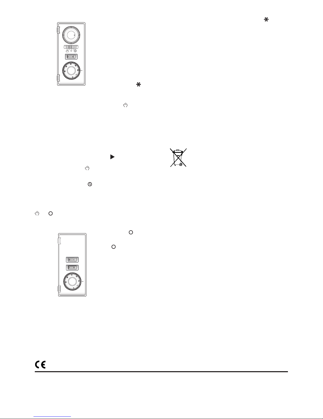
Fig. 3
Fig. 4
Operation - Timer Models
The slide switch on the timer unit
controls the electricity supply to the
heating elements.
The switch marked I - II (half heat –
full heat) provides a choice of output
as desired.
The heater is tted with an adjustable
th er mosta t enabl ing the ro om
temperature to be controlled by
adjusting the setting accordingly.
The thermostat has a minim um
setting represented by .
Providing the appliance has been switched ‘ON’ the heater will come on
when the surrounding temperature falls to approximately 6oC. This setting
may be used for protection against frost.
Switch on the heater by setting the slide switch to the manual position.
Turn the thermostat knob to max. and set selector switch (where tted) to
full heat, to warm the room rapidly.
When the room temperature has reached the desired level, turn the
thermostat knob back slowly until the thermostat just clicks o. The heater
will then maintain the room temperature at the chosen level, provided that
the correct size of heater has been selected for the room to be heated.
To set the time of day
The heater must be connected to the electricity supply for the timer to
operate. Set the timer by rotating the dial clockwise until the correct time
of day is indicated opposite the datum mark.
Manual Operation
Set the timer switch to manual . The heater will now operate continously
under the control of the thermostat.
Automatic Operation
Set the timer slide to automatic . Switching times can be selected in 20
minute steps. Set the desired programme by gently pulling the appropriate
segments out, proud of the dial face during the ‘On’ period. The timer may
be set to give as many ‘On’ periods of any length as may be required. The
programme will repeat itself every 24 hours until changed.
The programme may be over-ridden at any time by switching to manual
or to .
Operation - Non Timer Models
The switch marked and I controls
the electricity supply to the heating
el eme nts. The OFF po sit ion is
marked .
The switch marked I - II (half heat –
full heat) provides a choice of output
as desired.
The heater is tted with an adjustable
th er mosta t enabl ing the ro om
temperature to be controlled by
adjusting the setting accordingly.
Thermostat
The thermostat has a minimum setting represented by . Providing
the appliance has been switched ‘ON’ the heater will come on when
the surrounding temperature falls to approximately 6oC. This setting may
be used for protection against frost.
Switch on the heater and turn the thermostat knob to Max. and set selector
switch (where tted) to full heat, to warm the room rapidly.
When the room temperature has reached the desired level, turn the
thermostat knob back slowly until the thermostat just clicks o. The heater
will then maintain the room temperature at the chosen level, provided that
the correct size of heater has been selected for the room to be heated.
Useful Hints
Should your heater fail to operate please ensure:
1. The thermostat setting is higher than the room temperature
by turning the control knob to the maximum position.
2. The safety cut-out has not operated by following the
procedure as detailed in ‘Safety - Overheat protection’.
Safety - Overheat protection
For your safety this appliance is tted with a thermal cut-out. In the event
that the product overheats for some reason, the cut-out prevents excessive
temperatures on the product by cutting the power to the heater. Once the
heater has cooled down, it will reset automatically, it will continue to cycle
on and o automatically until the reason for overheating is removed.
Recycling
For electrical products sold within the European Community.
At the end of the electrical products useful life it should not
be disposed of with household waste. Please recycle where
facilities exist. Check with your Local Authority or retailer for
recycling advice in your country.
Cleaning
WARNING – ALWAYS DISCONNECT FROM THE POWER SUPPLY BEFORE
CLEANING THE HEATER.
Before commencing cleaning, switch o the heater and allow it to cool.
Disconnect the electricity supply to the appliance.
The outside can be cleaned by wiping it over with a soft damp cloth and
then dried. Do not use abrasive cleaning powders or furniture polish, as
this can damage the surface nish.
To release heater from the wall bracket for cleaning or redecoration,
depress latch on both brackets and hinge forward.
Specication subject to change without prior notice.
Supplied by APL
The product complies with the European Safety Standards EN60335-2-30 and the European Standard Elec tromagnetic Compatibility (EMC) EN55014, EN60555-2 and EN60555-3
These cover the essential requirements of EEC Directives 2006/95/EC and 2004/108/EC
439051A
 Loading...