

Page 1
Owner's Manual
Model
PF2325
PF3033
690932XXXX
7213450100R08
IMPORTANT SAFETY INFORMATION: Always read this manual rst before
attempting to install or use this replace. For your safety, always comply with
all warnings and safety instructions contained in this manual to prevent personal injury or property damage.
To view the full line of Dimplex products, please visit www.dimplex.com
Support Questions: Contact Dimplex at 888-346-7539
Sales Inquiries: Contact Sylvane at 800-934-9194 or visit
syvlane.com
Page 2
2 www.dimplex.com
Table of Contents
Always use a qualied technician or
service agency to repair this replace.
!
NOTE: Procedures and
techniques that are considered
important enough to emphasize.
CAUTION: Procedures and
techniques which, if not carefully
followed, will result in damage to the
equipment.
WARNING: Procedures and
techniques which, if not carefully
followed, will expose the user to
the risk of re, serious injury, or
death.
Welcome & Congratulations ..................3
IMPORTANT INSTRUCTIONS .................4
Fireplace Installation ........................6
Operation ................................10
Maintenance .............................15
Warranty .................................16
Replacement Parts .........................18
Page 3
3
Welcome & Congratulations
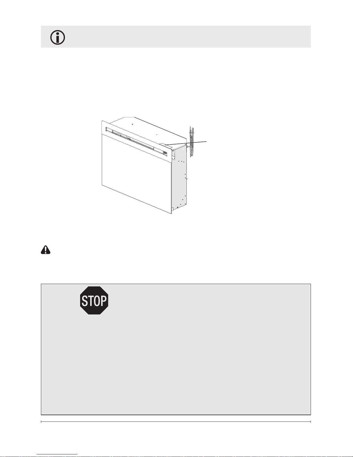
Model and Serial
Number Label
Thank you and congratulations for purchasing an electric replace from
Dimplex. Please use our convenient online registration page to record
your model and serial numbers for future reference at
www.dimplex.com/register
NO NEED TO RETURN TO THE STORE
Questions with operation or assembly? Require Parts Information?
Product Under Manufacturer’s Warranty?
Contact us at: www.dimplex.com/customer_support
For Troubleshooting and Technical Support
OR Toll-Free 1-888-DIMPLEX (1-888-346-7539)
Monday to Friday 8:00 a.m. to 4:30 p.m. EST
In order to better serve you, please have your model and serial number
ready or register your product online before calling (See above)
Please carefully read and save these instructions.
CAUTION: Read all instructions and warnings carefully before
starting installation. Failure to follow these instructions may result in
a possible electric shock, re hazard and will void the warranty.
Page 4

4 www.dimplex.com
When using electrical appliances,
basic precautions should always be
followed to reduce the risk of fire,
electric shock, and injury to persons,
including the following:
① Read all instructions before using
this appliance.
② The heater is hot when in use.
To avoid burns, do not let bare skin
touch hot surfaces. The trim around
the heater outlet becomes hot during
heater operation.
③ Extreme caution is necessary
when any heater is used by or near
children or invalids and whenever the
unit is left operating and unattended.
④ Always unplug the fireplace when
not in use.
⑤ Do not operate any heater after it
malfunctions. Disconnect power at
the service panel and have the unit
inspected by a reputable electrician
before reusing.
⑥ Do not operate any unit with a
damaged cord or plug, or if the heater
has malfunctioned, or if the electric
replace has been dropped or damaged in any manner, contact Dimplex
Technical Service at 1-888-346-7539.
⑦ Do not use outdoors.
⑧ Do not run the cord under carpet-
ing. Do not cover cord with throw
rugs, runners or the like. Arrange
IMPORTANT INSTRUCTIONS
cord away from trafc area and where
it will not be tripped over.
⑨ To disconnect the unit, turn the
controls off, then remove the plug
from the outlet.
⑩ Do not insert or allow foreign
objects to enter any ventilation or
exhaust opening as this may cause
an electric shock or re, or damage to
the heater.
⑪ To prevent a possible re, do not
block air intake or exhaust in any
manner.
⑫ All electrical heaters have hot and
arcing or sparking parts inside. Do
not use in areas where gasoline,
paint, or ammable liquids are used
or stored.
⑬ Do not modify the replace. Use it
only as described in this manual. Any
other use not recommended by the
manufacturer may cause re, electric
shock or injury to persons.
⑭ To reduce the risk of electric
shock, this appliance has a polarized plug (one blade is wider than the
other). This plug will t in a polarized
outlet only one way. If the plug does
not t fully in the outlet, reverse the
plug. If it still does not t, contact
a qualied electrician to install the
proper outlet. Do not change the plug
in any way.
Page 5

5
SAVE THESE INSTRUCTIONS
⑮ Always plug heaters directly
into a wall outlet/receptacle.
Never use with an extension cord
or relocatable power tap (outlet/
power strip).
⑯ Do not burn wood or other materi-
als in the electric replace.
⑰ Do not strike the replace glass.
⑱ Always use a certied electrician
should new circuits or outlets be
required.
⑲ Always use properly grounded,
fused and polarized outlets.
⑳ Disconnect all power supply before
performing any cleaning, maintenance or relocation of the unit.
㉑ When transporting or storing the
unit and cord, keep in a dry place,
free from excessive vibration and
store so as to avoid damage.
WARNING: Remote control
contains a small battery. Keep away
from children. If swallowed, seek
medical attention immediately.
WARNING: Do not install battery
backwards, charge, put in re or mix
with used or other battery types - may
explode or leak causing injury.
!
NOTE: Changes or modications
not expressly approved by the party
responsible for compliance could void
user's authority to operate the equip-
ment.
CAUTION: Connect to a prop-
erly grounded outlet only, see
Grounding Instructions.
IMPORTANT INSTRUCTIONS
CAUTION
RISK OF ELECTRIC SHOCK
DO NOT OPEN
NO USER-SERVICEABLE PARTS INSIDE
Page 6
6 www.dimplex.com
WARNING: Ensure the power
cord is not installed so that it is
pinched or against a sharp edge
and ensure that the power cord is
stored or secured to avoid tripping
or snagging to reduce the risk
of re, electric shock or injury to
persons.
WARNING: Construction
and electrical outlet wiring must
comply with local building codes
and other applicable regulations
to reduce the risk of re, electric
shock and injury to persons.
WARNING: Do not attempt
to wire your own new outlets or
circuits. To reduce the risk of re,
electric shock or injury to persons,
always use a licensed electrician.
WARNING: To reduce the risk
of re, do not store or use gasoline or other ammable vapors or
liquids in the vicinity of the heater.
Fireplace Installation
Grounding Instructions
This product must be grounded.
If it should malfunction or breakdown, grounding provides a path
of least resistance for electric
current to reduce the risk of
electric shock. This product is
equipped with a cord having an
equipment-grounding conductor
and a grounding plug. The plug
must be plugged into an appropri-
ate outlet that is properly installed
and grounded in accordance with
all local codes and ordinances.
DANGER: Improper connec-
tion of the equipment-grounding
conductor can result in a risk
of electric shock. Check with a
qualied electrician or serviceman
if you are in doubt as to whether
the product is properly grounded.
Do not modify the plug provided
with the product – if it will not t
the outlet, have a proper outlet
installed by a qualied electrician.
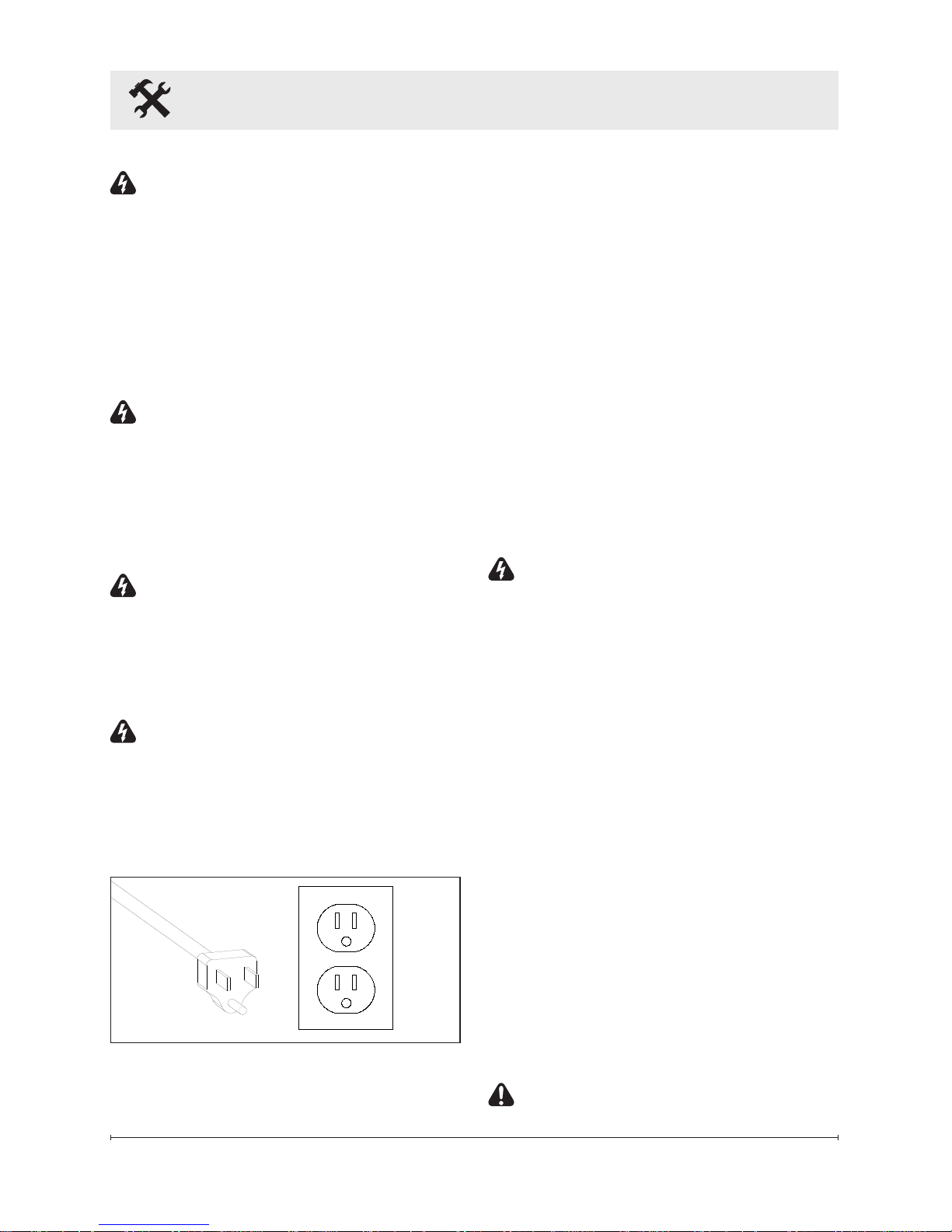
This product is for use on a
nominal 120-volt circuit and has
a grounding plug that looks like
the plug in Figure 1. Make sure
that the product is connected to
an outlet having the same conguration as the plug. No adapter
should be used with this product.
CAUTION: Clearance for air
Figure 1
Page 7
7
A
B
C
circulation beneath the replace insert is provided by 4
felt feet.
Do not install the replace
insert directly on carpet or
similar surfaces which may
restrict air circulation.
CAUTION: If installing the
replace in a carpeted area, place
a one-piece, solid, at surface under the replace. Ensure that all
feet rest securely on this surface.
!
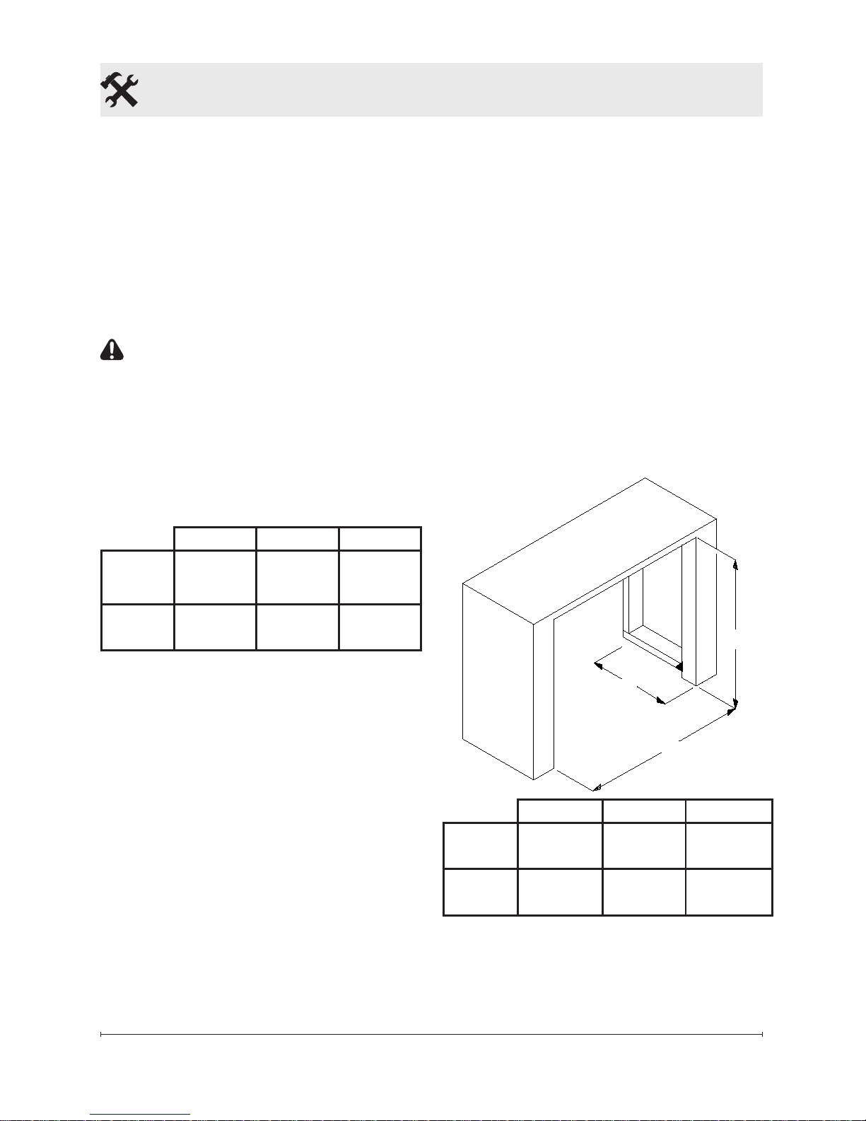
NOTE: The dimensions of the
rebox are:
Width Height Depth
PF2325
24.1in.
(612mm)
18.1in.
(459mm)
8.9in.
(225mm)
PF3033
31.3in.
(796mm)
22.5in.
(573mm)
8.9in.
(226mm)
Mantel Installation
Install the replace into the
mantel (refer to mantel assembly
instructions).
!
IMPORTANT: Install the man-
tel so that it is a minimum of ⅜ in.
(10 mm) off of the wall to ensure
adequate air ow.
!
IMPORTANT: If not using a
Dimplex mantel, the replace
must be installed in an enclosure
with the following minimum inter-
nal/opening dimensions - Figure 2.
Custom Mantel Construction
1. Frame an opening of, see
dimensions in Figure 2:
!
NOTE: On elevated instal-
lations, the bottom edge and ½
in. (13 mm) up either side will
be easily visible after installation (Figure 2). This area should
be nished in a manner that is
visually appealing and does not
restrict air ow to the unit.
Figure 2
Fireplace Installation
A B C
PF2325
25.0in.
(635mm)
18.5in.
(470mm)
10.0in.
(254mm)
PF3033
32.1in.
(816mm)
22.8in.
(579mm)
10.0in.
(254mm)
!
NOTE: The replace needs to be
installed to ensure 35 in2 (226 cm2) of
intake air, into the back of the unit, on
a continuous basis.
Page 8
8 www.dimplex.com
Fireplace Installation
Option #1 - The power cord can
be lead from behind the trim
and along the wall to an outlet
near the replace.
Option #2 - A new outlet can be
installed inside the new frame
construction. Plug the unit into
a 15 Amp/120 Volt outlet.
!
NOTE: A 15 Amp, 120 Volt
circuit is required. A dedicated
circuit is preferred but not essential in all cases. A dedicated circuit will be required
if, after installation, the circuit
breaker trips or fuse blows
on a regular basis when the
heater is operating. Additional
appliances on the same circuit
may exceed the current rating
of the circuit breaker.
Bathroom Installation
This rebox must be protected by
a GFI receptacle or circuit. If a
receptacle is used it must be readily
accessible.
To prevent electrical shock this unit
is an electrical appliance that is not
watertight and must be installed as to
prevent water from entering the unit.
This unit must be installed away from
showers, tubs, etc. Never locate replace where it may fall into a bathtub
or other water containers.
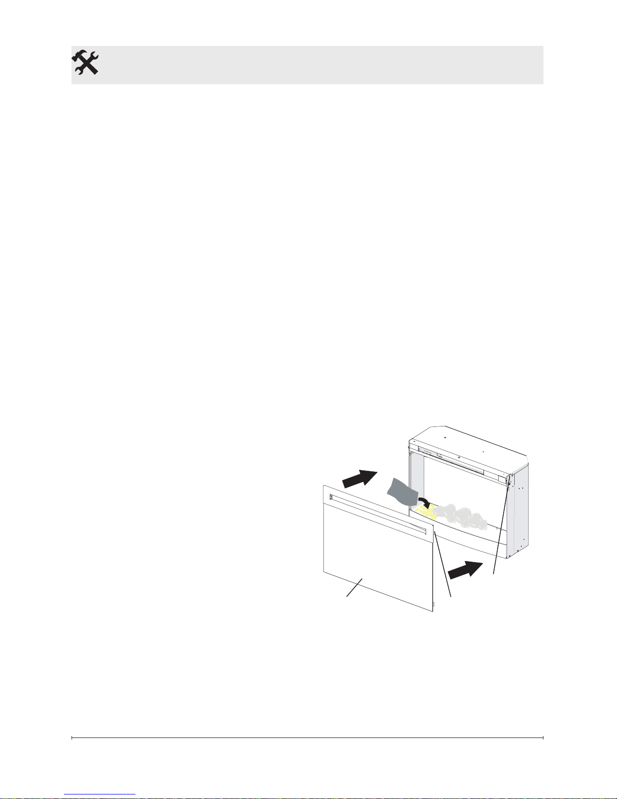
Figure 3
Front glass
Mounts
Hooks
Media Installation
Depending on the model, the media
may come installed in the unit or
packaged seperately.
Installed Media
• No additional steps are required.
Media Seperately Packaged
1. Remove the front glass by lifting
the 2 hooks off of the 2 mounts
on the rebox.
2. Place the large media in the
Media Tray in the center at the
back (for optimum media effect),
then carefully pour and evenly
distribute the smaller media into
the Media Tray.
3. Replace the front glass.
Page 9
9
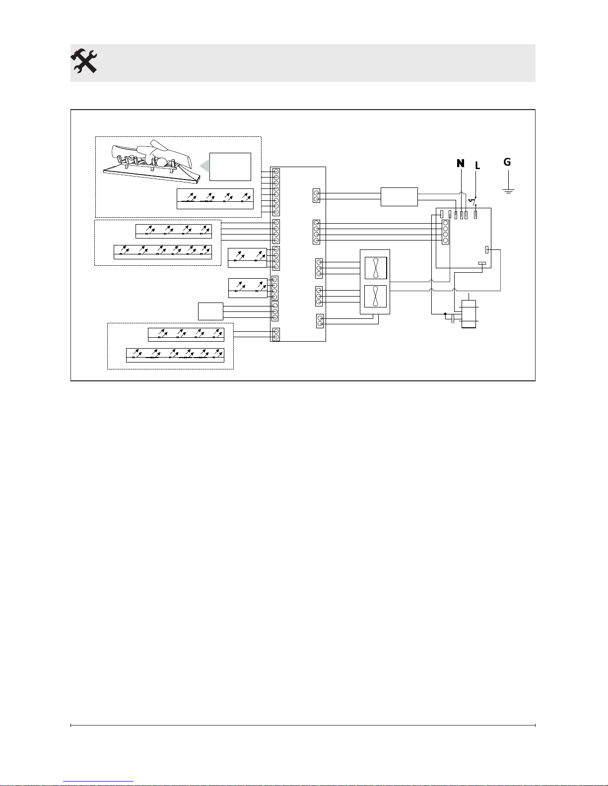
Wiring Diagram
L
G
GESTURE
ASSY
MAIN BOARD
NTC
TOP LIGHT ASSY
FLAME LED LIGHT ASSEMBLY (1W)
TOP LIGHT ASSY
FLICKER MOTOR
HEATER ASSEMBLY
MEDIA LED LIGHT ASSEMBLY
LOGSET JUNCTION BOARD
THERMAL
CUT OUT
OR
POWER SUPPLY
RELAY BOARD
OR
OR
FLAME BED LED ASSEMBLY (RGB)
Fireplace Installation
Page 10

10 www.dimplex.com
Operation
General Operation
WARNING: This electric rebox
must be properly installed before it is
used.
This rebox operates with
Comfort$averTM technology, which automatically adjusts the fan speed and
heater wattage to safely and precisely
match the requirements of the room
based on the thermostat setting. The
heater operates such that once the
room reaches the set point, the fan
and heater will continuously run at a
low level, to maintain the desired room
temperature. If the temperature in the
room rises signicantly, i.e. sun coming
through a window or a central furnace
turns on, the heater and fan will turn
off and periodically turn back on to circulate the air around the unit, until the
room temperature drops and requires
the heater to be constantly on again.
!
NOTE: The unit is designed so that
the fan will run continuously while the
heater is on.
!
NOTE: The element retains heat
after shutdown, there is a built in cool
down period of 1 minute before the
fan shuts off completely.
gWaveTM Controls
The replace can be operated by a
simple "wave" in-front of the unit. By
waving your hand vertically approximately 4 in. (102 mm) in-front of the
gWaveTM sensor in the upper right hand
corner of the unit, the unit and different
control functions can be activated. This
is also indicated by the LED light turning green.
There is a Gesture On/Off button
located below the LED pilot light
which can be used to turn this feature
On or Off (a more detailed description
is located below with the individual
feature options). It is recommended
that a straightened paperclip be used
to press the button through the small
hole. When the gWave
TM
controls are
turned off, the green light will ash
4 times before turning off and it will
remain solid green when the gWave
TM
controls are active.
!
NOTE: The unit is programmed to
have a built in demonstration mode to
exhibit all of the functions of the unit in
a 95 second period of time. This can be
activated by holding your hand infront
of the gWaveTM sensor for 7 seconds.
When the unit has gone through the
demonstration mode once it will return
to the previous operation.
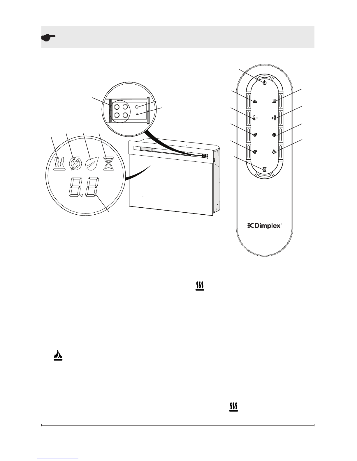
Remote Operation
The replace is supplied with an IR
multifunction remote control.
!
NOTE: To operate correctly,
the remote control must be pointed
towards the front of the unit.
Controls
1. Standby: Turns unit On or Off.
→ Activated by pressing the corresponding button on the remote
Page 11
11
or “waving” in-front of the gWaveTM. "Waving" up will turn the unit
On and "Waving" down will turn
the unit Off.
• The unit will turn on with the
same functions that it was set to
when it was turned Off and the intake temperature will be indicated
on the On Screen Display.
!
NOTE: When any button is
pressed the intake temperature will
be displayed on the On Screen Display for 5 seconds.
2. Flame On/Off: Turns the ame
effect On or Off.
→ Activated by pressing the cor-
responding button on the remote
or “waving” in-front of the gWaveTM.
Operation
• When On the ame effect is visible in the unit.
3. Heat On/Off: Turns the heater
On or Off.
→ Activated by pressing the cor-
responding button on the remote
or holding your hand in-front of
the gWaveTM for 3 seconds.
• Indicated by the icon and intake
temperature being illuminated on
the Floating Display™ and the
heater turning On or Off.
!
NOTE: The heater can be oper-
ated when the ame is not visible. In
this case the icon will remain on
Figure 4
①
②
③
③
④
⑤
⑥
⑥
⑦
⑦
⑧ ⑨
⑩
⑩
⑪
LED Pilot Light
gWave
TM
Controls
Gesture On/Off
Page 12
12 www.dimplex.com
Operation
the Floating Display™ until the heater
is turned off or the ames are turned
back on.
4. Temperature Down: Decreas-
es the heat output.
→ Adjusted by repeatedly press-
ing the corresponding button on
the remote.*
• Indicated by setpoint temperature on the Floating Display™
decreasing and the speed of the
fan decreasing to reduce the
amount of heat being projected
into the room.**
5. Temperature Up: Increases
the heat output.
→ Adjusted by repeatedly press-
ing the corresponding button on
the remote.*
• Indicated by the setpoint on the
Floating Display™ increasing and
the speed of the fan increasing to
increase the amount of heat being
projected into the room.
* The rst time the button is pressed
the current temperature set point will
be displayed for 5 seconds.
** The temperature can be adjusted
from 5 °C to 30 °C (41 °F to 86 °F).
!
NOTE: Pressing and holding the
, then pressing , will toggle
between °C and °F.
6. Eco: Runs the heater in a
reduced wattage range when
activated.
→ Adjusted by pressing the cor-
responding button on the remote
when the heater is on.
• Indicated by the icon being illuminated on the Floating Display™
and the speed of the fan will
decrease proportionally.
7. Boost: Turns On/Off the
heater boost function. Runs the
unit at the full rated wattage.
→ Activated and adjusted by repeatedly pressing the corresponding button on the remote.
• Indicated by the heater running
at full heat, for a predetermined
amount of time, to quickly heat
up a cold room/space. The Boost
can be set for a maximum of 20
minutes, in 5 minute increments.
8. Multi-Fire XD™: Different
presets of ambient lighting color
combinations contained in the
unit.
→ Changed by repeatedly pressing the corresponding button on
the remote.
• Cycles through the different
preset ambient lighting settings
of the unit, this includes different
combinations of colours of the top
lighting, ame base and media
lighting (if applicable).
!
NOTE: The last option is a per-
sonalized colour setting ("P"), where
Page 13
13
Operation
using the buttons on the remote the
lighting of the unit can be adjusted
to any shade of any colour. The
initial setting is no light (R=0, B=0,
G=0) and can be adjusted, while the
display is ashing, by pressing the
outlined buttons (below) to adjust the
tones.
• Red Tones: increase and the
decrease.
• Green Tones: increase and
decrease.
• Blue Tones: increase and
decrease.
!
NOTE: There are 25 different set-
tings for each colour.
9. Brightness: Changes the
brightness of the lights in the unit.
→ Adjusted by repeatedly press-
ing the corresponding button on
the remote.
• Indicated by the second digit on
the Floating Display™ changing
to show: "A" (high), "b" (low), "C"
(high with media icker) and "d"
(low with media icker).
!
NOTE: Media icker is not an
option on the Multi-Fire XD™ levels
5, 6 or P.
10. Sleep timer: turns the unit off
after a preset duration (from 30
minutes (0.5h) to 8 hours, in ½
hour increments).
→ Activated and adjusted by repeatedly pressing the corresponding button on the remote.
• Indicated by the Floating
Display™ changing to indicate
30 minutes (0.5 h) through 8
hours. The replace will automatically turn off when the sleep timer
reaches zero minutes. The sleep
timer can be cancelled at any time
by pressing the sleep timer button
repeatedly until the sleep timer
will no longer be visible.
11. Numerical Display
→ Default display will be the
heater air intake temperature or
settings (eg. Multifire XD, Brightness, etc.)
Disable Heat
If desired, depending on the season, the heater on the unit can be
disabled. The unit will operate in the
same fashion, with remainder of the
controls.
Pressing the then will enable
or disable the heater. When in the
heat disable mode the temperature
reading/setting on the On Screen
Display displays nothing ("--").
!
NOTE: The heat will not work in
manual controls either.
Page 14
14 www.dimplex.com
Operation
Resetting the Temperature
Cutoff Switch
Should the heater overheat, an automatic cut out will turn the replace off
and it will not come back on without
being reset. It can be reset by unplug-
ging the unit and waiting 15 minutes
before plugging the unit back in.
Once power is restored the unit will
start to reset itself. During this process you will hear repeated beeps
and the display may turn on and off.
CAUTION: If you need to continu-
ously reset the heater, disconnect
power and call Dimplex customer
service at 1-888-DIMPLEX
(1-888-346-7539).
Battery Replacement (Figure 4)
To replace the battery:
1. Slide battery cover open on the
back of the remote control.
2. Install one 3V (CR 2032) battery
in the battery holder.
3. Close the battery cover.
Battery must be recycled or
disposed of properly. Check
with your Local
Authority or Retailer for recycling
advice in your area.
Page 15
15
Maintenance
WARNING: Disconnect power
before attempting any maintenance
or cleaning to reduce the risk of re,
electric shock or damage to persons.
CAUTION: Allow adequate time
for the element and body casing to
cool before attempting to clean the
unit.
It is suggested that the heater be
inspected regularly, for cleanliness of
the fan exhaust and intake grille, to
ensure optimal performance is maintained. The grille can be cleaned by
vacuuming off all dust and dirt.
Glass Cleaning
The front glass is cleaned in the
factory during the assembly operation. During shipment, installation,
handling, etc., the front glass may
collect dust particles, these can be
removed by dusting lightly with a
clean dry cloth.
To remove ngerprints or other
marks, the glass can be cleaned with
a damp cloth. The glass should be
completely dried with a lint free cloth
to prevent water spots. To prevent
scratching, do not use abrasive
cleaners or spray liquids on the glass
surface.
Fireplace Surface Cleaning
To remove ngerprints or other
marks, the exterior nish can be
cleaned with a damp cloth with a mild
detergent. The surface should be
completely dried with a lint free cloth
to prevent water spots.
Servicing
Except for installation and cleaning
described in this manual, an authorized service representative should
perform any other servicing.
Page 16

16 www.dimplex.com
Warranty
Products to which this limited warranty
applies
This limited warranty applies to the
following models of your newly purchased
Dimplex electric replace 690932XXXX
and to newly purchased Dimplex replace
surrounds and trims. This limited warranty
applies only to purchases made in any
province of Canada except for Yukon
Territory, Nunavut, or Northwest Territories
or in any of the 50 States of the USA (and
the District of Columbia) except for Hawaii
and Alaska. This limited warranty applies
to the original purchaser of the product
only and is not transferable.
Products excluded from this limited
warranty
Products purchased in Yukon Territory,
Nunavut, Northwest Territories, Hawaii,
or Alaska are not covered by this limited
warranty. Products purchased in these
States, provinces, or territories are sold
AS IS without warranty or condition of
any kind (including, without limitation,
any implied warranties or conditions of
merchantability or tness for a particular
purpose) and the entire risk of as to the
quality and performance of the products is
with the purchaser, and in the event of a
defect the purchaser assumes the entire
cost of all necessary servicing or repair.
What this limited warranty covers and for
how long
Products, other than replace surrounds
(mantels) and trims, covered by this
limited warranty have been tested and
inspected prior to shipment and, subject
to the provisions of this warranty, Dimplex
warrants such products to be free from
defects in material and workmanship for a
period of 1 year from the date of the rst
purchase of such products.
The limited 1 year warranty period also
applies to any implied warranties that
may exist under applicable law. Some
jurisdictions do not allow limitations on
how long an implied warranty lasts, so
the above limitation may not apply to the
purchaser.
What this limited warranty does not cover
This limited warranty does not apply to
products that have been repaired (except
by Dimplex or its authorized service
representatives) or otherwise altered. This
limited warranty does further not apply
to defects resulting from misuse, abuse,
accident, neglect, incorrect installation,
improper maintenance or handling, or
operation with an incorrect power source.
What you must do to get service under
this limited warranty
Defects must be brought to the attention of
Dimplex Technical Service by contacting
Dimplex at 1-888-DIMPLEX (1-888346-7539), or 1367 Industrial Road,
Cambridge Ontario, Canada N1R 7G8.
Please have proof of purchase, catalogue/
model and serial numbers available when
calling. Limited warranty service requires a
proof of purchase of the product.
What Dimplex will do in the event of a
defect?
In the event a product or part covered
by this limited warranty is proven to be
defective in material or workmanship
during the 1 year limited warranty period
you have the following rights:
• Dimplex will in its sole discretion
either repair or replace such defective
Page 17

17
product or part without charge. If
Dimplex is unable to repair or replace
such product or part, or if repair or
replacement is not commercially
practicable or cannot be timely made,
Dimplex may, in lieu of repair or
replacement, choose to refund the
purchase price for such product or
part.
• Limited warranty service will be
performed solely by dealers or service
agents of Dimplex authorized to
provide limited warranty services.
• Dimplex will not be responsible for,
and the limited warranty services shall
not include, any expense incurred for
installation or removal of the product
or part (or any replacement product or
part) or any labour or transportation
costs. Such costs shall be the
purchaser’s responsibility.
What Dimplex and its dealers and service
agents are also not responsible for:
IN NO EVENT WILL DIMPLEX, OR ITS
DIRECTORS, OFFICERS, OR AGENTS,
BE LIABLE TO the PURCHASER OR
ANY THIRD PARTY, WHETHER IN
CONTRACT, IN TORT, OR ON ANY
OTHER BASIS, FOR ANY INDIRECT,
SPECIAL, PUNITIVE, EXEMPLARY,
CONSEQUENTIAL, OR INCIDENTAL
LOSS, COST, OR DAMAGE ARISING
OUT OF OR IN CONNECTION WITH
THE SALE, MAINTENANCE, USE, OR
INABILITY TO USE THE PRODUCT,
EVEN IF DIMPLEX OR ITS DIRECTORS,
OFFICERS, OR AGENTS HAVE BEEN
ADVISED OF THE POSSIBILITY OF
SUCH LOSSES, COSTS OR DAMAGES,
OR IF SUCH LOSSES, COSTS, OR
DAMAGES ARE FORESEEABLE. IN
NO EVENT WILL DIMPLEX, OR ITS
OFFICERS, DIRECTORS, OR AGENTS
BE LIABLE FOR ANY DIRECT LOSSES,
COSTS, OR DAMAGES THAT EXCEED
THE PURCHASE PRICE OF THE
PRODUCT.
SOME JURISDICTIONS DO NOT ALLOW
THE EXCLUSION OR LIMITATION OF
INCIDENTAL OR CONSEQUENTIAL
DAMAGES, SO THE ABOVE LIMITATION
OR EXCLUSION MAY NOT APPLY TO
THE PURCHASER.
How State and Provincial law apply
This limited warranty gives you specic
legal rights, and you may also have other
rights which vary from jurisdiction to
jurisdiction. The provisions of the United
Nations Convention on Contracts for
the Sale of Goods shall not apply to this
limited warranty or the sale of products
covered by this limited warranty.
Warranty
Page 18

Flicker Motor .......................................2000480100RP
Heater Assembly (with cutout) ..........................2203650100RP
Cord Set ..........................................4100190400RP
Remote Control . . . . . . . . . . . . . . . . . . . . . . . . . . . . . . . . . . . . . 3001250100RP
Main Control Board with Display . . . . . . . . . . . . . . . . . . . . . . . . 3001530100RP
gWave
TM
Assembly ..................................3001620100RP
Relay Board. . . . . . . . . . . . . . . . . . . . . . . . . . . . . . . . . . . . . . . . 3001540100RP
Power Supply ......................................2100250300RP
Logset Junction Board. . . . . . . . . . . . . . . . . . . . . . . . . . . . . . . . 3001600100RP
Top Light Assembly ..................................3001290100RP
PF23 PF33
Log Set ........................
0441690200RP 0441540200RP
Media Tray (Flat) . . . . . . . . . . . . . . . . . 0441580100RP 0441580200RP
Front Glass (Flat). . . . . . . . . . . . . . . . . 1026770400RP 1026770600RP
Media Tray (Curved) .............. 0441580300RP N/A
Front Glass (Curved). . . . . . . . . . . . . . 1026770700RP N/A
Partially Reective Glass ........... 5902750100RP 5902750400RP
Brick Panels. . . . . . . . . . . . . . . . . . . . . 0441600100RP 0441600300RP
Flicker Assembly ................. 5902830100RP 5902830200RP
Media LED Light Assembly ......... 3001330700RP 3001330600RP
Ember LED Light Assembly ........ 3001300100RP 3001300200RP
Flame LED Light Assembly (1W). . . . . 3001310100RP 3001310300RP
Flame Bed LED Assembly (RGB) .... 3001330200RP 3001330400RP
© 2015 Dimplex North America Limited
Dimplex North America Limited
1367 Industrial Road
Cambridge ON
Canada N1R 7G8
Replacement Parts
Page 19

Manuel du propriétaire
Modéle
PF2325
PF3033
690932XXXX
7213450100R08
CONSIGNES DE SÉCURITÉ IMPORTANTES : Toujours lire le présent manuel
avant d’essayer d’installer ou d’utiliser ce foyer. Pour votre sécurité, toujours
respecter tous les avertissements et suivre les consignes de sécurité compris
dans le présent manuel an de prévenir les blessures ou les dommages
matériels.
Pour découvrir la gamme complète de produits Dimplex,
visiter www.dimplex.com.
Page 20

2 www.dimplex.com
Table des matières
Toujours recourir aux services d’un
technicien qualié ou d’une entreprise
de services d'entretien pour faire
réparer ce foyer.
!
NOTE: Marches à suivre et
techniques considérées sufsamment
importantes pour qu’on les souligne.
MISE EN GARDE : Marches
à suivre et techniques qui, si elles
ne sont pas bien respectées,
endommageront le matériel.
AVERTISSEMENT : Marches à
suivre et techniques qui, si elles
ne sont pas bien respectées,
exposeront l’utilisateur à des
risques d’incendie, de blessure
grave ou de décès.
Bienvenue et félicitations .....................3
INSTRUCTIONS IMPORTANTES ...............4
Installation du foyer .........................6
Utilisation ................................10
Entretien ................................15
Garantie .................................16
Pièces de rechange .........................18
Page 21

3
Bienvenue et félicitations
Étiquette du numéro
de modèle et série
Merci et félicitations d’avoir acheté un foyer électrique fabriqué par Dimplex.
Veuillez utiliser notre page d'inscription en ligne pour inscrire votre modèle et
vos numéros de série à des ns de référence ultérieure à l'adresse
www.dimplex.com/enregister
IL N'EST PAS NÉCESSAIRE D'ALLER AU MAGASIN
Des questions à propos de l'utilisation ou du montage? Besoin d'information sur les pièces?
Besoin d'information à propos d'un produit sous une garantie du fabricant?
Communiquer avec nous à : www.dimplex.com/customer_support
Pour le dépannage et le Service d'assistance technique
OU Sans frais au 1-888-DIMPLEX (1-888-346-7539)
Du lundi au vendredi, de 8 h à 16 h 30 HE
An que nous puissions mieux vous servir, veuillez avoir votre modèle et votre
numéro de série à portée de main ou veuillez inscrire votre produit en ligne avant de
téléphoner (voir ci-dessus).
Lire ces consignes attentivement et les conserver.
MISE EN GARDE: Lire attentivement toutes les consignes et tous les
avertissements avant de procéder à l'installation. Le non-respect de ces
consignes pourrait entraîner un risque de choc électrique ou d'incendie et
annulera la garantie.
ARRÊT
Page 22

4 www.dimplex.com
Lorsqu’un appareil électrique est
utilisé, il est important de toujours
prendre des précautions de base
pour réduire les risques d’incendie,
de chocs électriques et de blessures,
notamment :
① Lire toutes les instructions avant
d'utiliser cet appareil.
② L'élément chauffant devient chaud
lorsqu’il est en marche. Pour éviter
les brûlures, ne pas toucher les surfaces chaudes. La bordure autour de
la bouche de chaleur devient chaude
lorsque les éléments chauffent.
③ Faire preuve d’une grande pru-
dence lorsque l’appareil est utilisé par
des enfants ou des personnes handicapées, s’il est en marche à proximité
d’eux, ou s’il est en marche et laissé
sans surveillance.
④ Toujours débrancher le foyer
lorsqu’il n’est pas utilisé.
⑤ Ne pas utiliser un appareil de
chauffage après une défaillance.
Interrompre le courant au tableau de
commande et faire inspecter l'appa-
reil par un électricien qualié avant de
le réutiliser.
⑥ Ne pas se servir de l’appareil si la
fiche ou le cordon sont endommagés,
si l'élément chauffant fonctionne mal
ou si le foyer électrique est tombé ou
est endommagé de quelque manière
que ce soit. Communiquer avec le
service technique de Dimplex au
1 888 346-7539.
⑦ Ne pas utiliser à l’extérieur.
INSTRUCTIONS IMPORTANTES
⑧ Ne pas faire passer le cordon sous
un tapis. Ne pas couvrir le cordon
de carpettes, de tapis de couloir ou
autres recouvrements de sol. Éloigner le cordon des endroits passants
et éviter de le placer là où il pourrait
provoquer la chute d’une personne.
⑨ Pour débrancher l'appareil, l'éteindre, puis retirer la che de la prise de
courant.
⑩ Ne pas introduire ou permettre
l'introduction de corps étrangers
dans la prise d’air de ventilation ou la
bouche de sortie d’air, car cela peut
occasionner des chocs électriques,
provoquer un incendie ou endommager l'appareil.
⑪ Pour éviter un incendie, ne pas
obstruer l’entrée ou la sortie d’air
d’aucune façon.
⑫ Tous les appareils chauffants élec-
triques contiennent des pièces qui
chauffent et qui peuvent produire un
arc électrique ou des étincelles. Ne
pas faire fonctionner l'appareil dans
des endroits où de l’essence, de la
peinture ou d'autres produits inammables sont utilisés ou entreposés.
⑬ Ne pas apporter de modications
au foyer. Se servir du foyer uniquement de la façon décrite dans le
présent guide. Toute autre utilisation
non recommandée par le fabricant
peut causer un incendie, des chocs
électriques ou des blessures.
⑭ An de réduire les risques de choc
électrique, cet appareil est muni d’une
Page 23

5
che polarisée (une des broches est
plus large que l’autre). Cette che se
branche dans une prise polarisée, et
ce, dans un sens seulement. S’il est
impossible d’enfoncer complètement
la che dans la prise, il faut l’inverser. S'il est toujours impossible de
l'enfoncer complètement, communi-
quer avec un électricien qualié pour
faire installer une prise adéquate. Ne
modier la che d'aucune façon.
⑮ Toujours brancher les appareils di-
rectement dans une prise de courant
murale. Ne jamais utiliser de rallonge
ou de barre d'alimentation portative.
⑯ Ne pas brûler de bois ni d’autres
matériaux dans ce foyer électrique.
⑰ Ne pas frapper sur la vitre frontale
du foyer.
⑱ Toujours faire appel à un élec-
tricien certié pour l’installation de
nouveaux circuits ou de nouvelles
prises de courant.
⑲ Toujours utiliser des prises correctement mises à la terre, polarisées
et protégées par un fusible ou un
disjoncteur.
⑳ Fermer toute source d’alimentation
électrique du foyer avant de le nettoyer, de le réparer ou de le déplacer.
㉑ Pendant le transport ou l’entreposage de l’appareil, le conserver dans
un endroit sec et à l’abri de vibrations
excessives, et le ranger de façon à
éviter qu’il ne s’endommage.
AVERTISSEMENT : La télé-
commande contient une petite pile.
Garder hors de la portée des enfants.
Si elles sont avalées, consulter immédiatement un médecin.
AVERTISSEMENT : Ne pas
installer la pile à l'envers, la charger,
la mettre au feu ou l'utiliser avec des
piles usées ou un autre type de pile,
car cela risque d'entraîner une explosion ou une fuite pouvant causer des
blessures.
!
NOTE: Les changements ou les
modications n’ayant pas fait l’objet
d’une approbation expresse de la
partie responsable de la conformité
auront pour effet d’annuler le droit
d’utilisation de l’appareil par l’utilisateur.
ATTENTION : Brancher l'appa-
reil dans une prise de courant mise
à terre seulement, voir les instructions de mise à la terre.
INSTRUCTIONS IMPORTANTES
CONSERVER CES INSTRUCTIONS
MISE EN GARDE
RISQUE DE CHOC ÉLECTRIQUE - NE PAS OUVRIR
AUCUNE PIÈCE DONT L'ENTRETIEN PEUT ÊTRE EFFECTUÉ
PAR L'UTILISATEUR NE SE TROUVE À L'INTÉRIEUR
Page 24

6 www.dimplex.com
AVERTISSEMENT : Veiller à ce
que le cordon d’alimentation ne soit
ni coincé ni disposé contre un bord
tranchant, mais rangé ou placé de façon à éviter tout risque d’accrochage
susceptible de causer un incendie,
des chocs électriques ou des bles-
sures.
AVERTISSEMENT : An de
réduire les risques d’incendie, de
choc électrique et de blessure, tous
les travaux de construction et de
câblage doivent être conformes au
Code du bâtiment et aux autres règle-
ments qui s’appliquent.
AVERTISSEMENT : Ne pas
tenter d'installer de nouvelles prises
ni de nouveaux circuits électriques
soi-même. Pour minimiser les risques
d’incendie, de choc électrique et de
blessure, toujours faire appel à un
électricien certié.
AVERTISSEMENT : An de
réduire les risques d'incendie,
éviter de conserver ou d’utiliser de
l’essence, d’autres liquides inammables ou des gaz inammables à
proximité de l'appareil.
Installation du foyer
Instructions de mise à la terre
Cet appareil doit être mis à la terre.
Advenant une défectuosité ou une
panne, la mise à la terre permet au
courant de suivre un trajet de moindre
résistance et réduit ainsi le risque de
chocs électriques. Le cordon électrique de cet appareil comporte un
conducteur de terre ainsi qu’une che
à broche de terre. La che doit être
branchée dans une prise assortie,
bien installée et mise à la terre selon
le code de l’électricité et les règlements municipaux.
DANGER: Si le conducteur de
mise à la terre est mal branché, il y a
risque de chocs électriques. Communiquer avec un électricien ou un
réparateur qualié en cas de doute
sur la mise à la terre appropriée de
l'appareil. Ne pas modier la che; s’il
est impossible de l'enfoncer dans la
prise, la faire remplacer la prise par
un électricien qualié.
Cet appareil doit être alimenté par
un circuit d'intensité nominale de 120
V et possède une che de mise à la
terre qui ressemble à la che montrée
à la gure 1. S'assurer que l'appareil
est raccordé à une prise de même
conguration que la che. N'utiliser
aucun adaptateur avec cet appareil.
MISE EN GARDE : Les 4 pieds
en feutre procurent le dégagement nécessaire à la circulation
de l’air sous le foyer.
Figure 1
Page 25

7
A
B
C
Ne pas installer le foyer encastrable directement sur un tapis
ou toute autre surface susceptible de réduire la circulation
d’air sous l’appareil.
MISE EN GARDE : En cas
d’installation du foyer sur une surface
couverte de tapis, le placer d’abord
sur une surface unie, droite et solide.
S’assurer que tous les pieds du foyer
reposent bien sur cette surface.
!
NOTE: Dimensions du foyer :
Largeur Hauteur Profondeur
PF2325
24,1po
(612mm)
18,1po
(459mm)
8,9po
(225mm)
PF3033
31,3po
(796mm)
22,5po
(573mm)
8,9po
(226mm)
Installation du manteau
Installer le foyer à l’intérieur du manteau (consulter les instructions de
montage du manteau).
!
IMPORTANT : Installer le man-
teau à au moins 10 mm (⅜ po) du
mur pour assurer une circulation d'air
adéquate.
!
IMPORTANT : Si le foyer n’est
pas installé dans un manteau de
cheminée Dimplex, il doit être installé
dans une enceinte ayant les dimensions internes/ouverture minimales
suivantes (Figure 2).
Construction de manteau
personnalisé
1. Pratiquer une ouverture selon
les dimensions indiquées à la
Figure 2.
!
NOTE: Dans le cas d'installations
élevées, le bord inférieur et les bords
latéraux de 1/2 po (13 mm) seront
clairement visibles après l'installation
(Figure 2). Cette surface doit être
nie à des ns esthétiques et de
façon à ne pas obstruer la circulation
d'air vers l'appareil.
Figure 2
Installation du foyer
A B C
PF2325
25,0po
(635mm)
18,5po
(470mm)
10,0po
(254mm)
PF3033
32,1po
(816mm)
22,8po
(579mm)
10,0po
(254mm)
!
NOTE: Le foyer doit être installé
de façon à assurer une admission
d'air de 226 cm2 (35 po2) à l'arrière
de l'appareil en tout temps.
Page 26

8 www.dimplex.com
Installation du foyer
Option #1 - Le cordon d’alimentation
peut être passé derrière la garniture du foyer pour longer le mur
jusqu’à une prise de courant près
du foyer.
Option #2 - Une nouvelle prise de
courant peut être installée dans le
nouveau cadre. Brancher le foyer
dans une prise de courant de
15A /120V.
!
NOTE: Un circuit de 15 am-
pères et de 120 volts est nécessaire. Un circuit spécialisé est
préférable, mais pas essentiel
dans tous les cas. Un circuit
spécialisé sera nécessaire si,
après l’installation, le disjoncteur
se déclenche ou si le fusible saute
régulièrement pendant le fonctionnement de l'élément chauffant.
L’ajout d’appareils sur le même
circuit risque d’excéder la puissance nominale du disjoncteur.
Installation dans une salle de
bain
Ce foyer doit être protégé par une
prise à disjoncteur ou un circuit de
fuite à la terre. Si une prise de cou-
rant est utilisée, elle doit être facilement accessible.
Pour prévenir tout risque de chocs
électriques, cet appareil électrique
non étanche à l’eau doit être installé
de façon à éviter que de l’eau ne s’y
inltre. Cet appareil doit être installé
loin de la douche, du bain, etc. Ne
Figure 3
Vitre frontale
Montants
Crochets
jamais installer l’appareil à un endroit
où il est susceptible de tomber dans
une baignoire ou dans tout autre
réservoir d’eau.
Installation des matériaux
incandescents
Selon le modèle, il est possible
que les galets soient installés dans
l'appareil ou emballés séparément.
Matériaux installés
• Aucune autre étape n'est requise.
Matériaux emballés séparément
1. Retirer la vitre frontale en retirant
les 2 crochets des 2 montants du
foyer.
2. Placez les grandes galets dans la
tablette avant, au centre à l'arrière
(pour l'effet médiatique optimale),
puis versez délicatement et dis-
tribuer les petites galets dans la
tablette avant uniformément.
3. Remettre la vitre frontale en
place.
Page 27

9
L
G
MONTAGE DU
TABLEAU DE
GWAVE
MC
CARTE DE CONTRÔLE PRINCIPALE
NTC
ASSEMBLÉE LUMIÈRE HAUT
ENSEMBLE D'ÉCLAIRAGE À DEL (FLAMME)
MOTEUR DE
L’EFFET DE
FLAMME
MONTAGE DE L'ÉLÉMENT CHAUFFANT
ENSEMBLE D'ÉCLAIRAGE À DEL (MATÉRIAUX INCANDESCENTS)
CARTE DE JONCTION POUR L'ENSEMBLE DE BÛCHES
THERMORUPTEURS
OU
BLOC D'ALIMENTATION
CARTE RELAIS
OU
ASSEMBLÉE LUMIÈRE HAUT
OU
ENSEMBLE D'ÉCLAIRAGE À DEL (LIT DE LA FLAMME) RBG
Schéma de câblage
Installation du foyer
Page 28

10 www.dimplex.com
Utilisation
Utilisation générale
AVERTISSEMENT : Ce foyer
électrique doit être installé correctement avant son utilisation.
Ce foyer fonctionne avec la technologie Comfort$averMC, qui ajuste
automatiquement la vitesse du ventilateur et radiateur puissance pour
correspondre en toute sécurité et
avec précision les besoins de la pièce
en fonction du réglage du thermostat. Lorsque l'appareil a réchauffé la
pièce à la température réglée, son
ventilateur et son élément chauffant
continuent de fonctionner à un niveau
bas, an de maintenir la température
voulue. Si la température de la pièce
augmente de façon signicative, à
savoir soleil à travers une fenêtre ou
un four central s'allume, le chauffage
et le ventilateur s'éteignent et périodiquement tourner le dos à faire circuler l'air autour de l'appareil, jusqu'à
ce que les gouttes à température
ambiante et nécessite le chauffage
d'être constamment sous tension.
!
NOTE: L'appareil est conçu pour
que le ventilateur fonctionne continuellement pendant que l'élément
chauffant est activé.
!
NOTE: L'élément chauffant
conserve la chaleur après avoir été
éteint; il y a une période de refroidissement de 1 minute avant que
le ventilateur ne s'éteigne complètement.
Commandes gWave
MC
Le foyer peut fonctionner par un
simple geste de la main à l'avant de
l'appareil (une description plus détaillée se trouve au-dessous avec les options de fonctionnalités individuelles).
En agitant la main verticalement à
approximativement 4 po (102 mm) à
l'avant du capteur gWaveMC dans le
coin supérieur droit de l'appareil, le
foyer et différentes fonctions peuvent
être activés; cette activation est aussi
indiquée par un voyant à DEL qui
passe au vert.
Un bouton marche/arrêt situé sous le
voyant pilote à DEL peut être utilisé
pour activer ou désactiver la fonction de commande gestuelle. Il est
recommandé d'utiliser un trombone
à papier déplié pour appuyer sur
ce bouton à travers le petit orice.
Lorsque les contrôles gWaveMC sont
éteints la lumière verte, clignote 4
fois avant de couper et il restera vert
lorsque les contrôles gWaveMC sont
actifs.
!
NOTE: L'appareil est programmé
pour qu'un mode de démonstration
intégré illustre toutes les fonctions
du foyer en 95 secondes. Ce mode
peut être activité en tenant la main
devant le capteur gWaveMC durant
7 secondes. Lorsque le mode de
démonstration est terminé, le mode
d'utilisation est réactivé.
Page 29

11
Utilisation de la télécommande
Le foyer est livré avec une télécommande multifonction à RI.
!
NOTE: Pour qu'elle fonctionne
correctement, la télécommande doit
être pointée vers l'avant de l'appareil.
Commandes
1. Mode veille : Pour activer ou
désactiver l'appareil.
→ Activé en appuyant sur la
touche correspondante de la télécommande ou en agitant la main
devant le gWaveMC. Agiter la main
vers le haut pour activer l'appareil
et agiter la main vers le bas pour
le désactiver.
• L'appareil se met en marche
en activant les mêmes fonctions
qui étaient réglées au moment
Utilisation
de l'arrêt, et la température de
l'air d'admission est indiquée à le
Floating DisplayMC.
!
NOTE: À la pression de n'importe
quelle touche, la température de l'air
d'admission apparaît à le Floating
Display™ pendant 5 secondes.
2. Activation/désactivation
de la amme : Pour activer ou
désactiver l'effet de amme.
→ Activé en appuyant sur la
touche correspondante de la télécommande ou en agitant la main
devant le gWaveMC.
• Si activé, l'effet de amme est
visible dans l'appareil.
Figure 4
①
②
③
③
④
⑤
⑥
⑥
⑦
⑦
⑧ ⑨
⑩
⑩
⑪
Lampe pilote à DEL
Commandes
gWave
MC
Marche/arrêt
des commandes
gestuelles
Page 30

12 www.dimplex.com
Utilisation
3. Activation/désactivation
de la chaleur : Pour activer ou
désactiver l'élément chauffant.
→ Activé en appuyant sur la
touche correspondante de la
télécommande ou en tenant la
main devant le gWaveMC pendant
3 secondes.
• Indiqué par l'icône, par l'illumination de la température de
l'air d'admission à le Floating
Display™ et par l'activation ou
la désactivation de l'élément
chauffant.
!
NOTE: Le chauffage peut être
utilisé lorsque la amme n'est pas
visible. Dans ce cas, l'icône restera
sur le Floating Display
MC
jusqu'à ce
que le chauffage est éteint ou les
ammes sont remises en marche.
4. Diminution de la température : Pour réduire la chaleur.
→ Réglé en appuyant à répétition
sur la touche correspondante de
la télécommande.*
• Indiqué par la réduction de
la température sur le Floating
DisplayMC et par la réduction de la
vitesse du ventilateur permettant
de diminuer la chaleur émise dans
la pièce.**
5. Hausse de la température :
Pour accroître la chaleur.
→ Réglé en appuyant à répétition
sur la touche correspondante de
la télécommande.*
• Indiqué par la hausse de la
température sur le Floating DisplayMC et par l'accroissement de la
vitesse du ventilateur permettant
d'augmenter la chaleur émise
dans la pièce.**
*À la première pression de la touche,
la température programmée apparaît
à le Floating Display™ pendant 5
secondes.
** La température peut être réglée de
5 et 30 °C (41 à 86 °F).
!
NOTE: Appuyez et maintenez
sur le bouton , ensuite , pour
alterner entre les degrés Celsius (°C)
et Fahrenheit (°F).
6. Économie d'énergie :
Fonctionner le chauffage dans
une plage de puissance réduite
lorsqu'il est activé.
→ Réglé en appuyant sur la
touche correspondante de la télécommande lorsque le chauffage
est en marche.
• Indiqué par l'illumination de
l'icône à le Floating Display™ et
par la diminution proportionnelle
de la vitesse du ventilateur.
7. Surpuissance : Pour activer/
désactiver la fonction de surpuissance de l'élément chauffant.
Exécute l'unité à la puissance
nominale maximale.
→ Activé et réglé en appuyant à
Page 31

13
Utilisation
répétition sur la touche correspondante de la télécommande.
• Indiqué par le fonctionnement
de l'élément à pleine capacité
pendant une durée prédéterminée
an de réchauffer rapidement une
pièce ou un endroit froid. Cette
fonction peut être réglée pour
un maximum de 20 minutes, par
tranches de 5 minutes.
8. Multi-Fire XDMC : L'appareil
comporte différentes combinaisons d'éclairage ambiant et de
couleurs.
→ Changé en appuyant à répéti-
tion sur la touche correspondante
de la télécommande.
• Active alternativement les
différents paramètres d'éclairage
ambiant de l'appareil, soit les
diverses combinaisons de cou-
leurs des ampoules supérieures
et bas ainsi que de l'éclairage des
matériaux incandescents (le cas
échéant).
!
NOTE: La dernière option (P)
propose le réglage de couleurs
personnalisées; à l'aide des touches
de la télécommande, l'éclairage de
l'appareil peut être réglé selon divers
tons de couleur. Le paramètre initial
« pas de lumière » (R=0, B=0, G=0)
peut être réglé, lorsque le Floating
Display™ clignote, en appuyant sur
les touches décrites ci-dessous pour
modier les tons.
• Tons de rouge : pour augmen-
ter et pour diminuer.
• Tons de vert : pour augmenter
et pour diminuer.
• Tons de bleu : pour augmenter
et pour diminuer.
!
NOTE: Il ya 25 paramètres diffé-
rents pour chaque couleur.
9. Clarté : Pour modier la clarté
de l'éclairage de l'appareil.
→ Réglé en appuyant à répétition
sur la touche correspondante de
la télécommande.
• Indiqué par le deuxième chiffre
sur le Floating Display™ changer
de montrer : «A» (élevée), «b»
(faible), «C» (élevée avec effet de
matériaux incandescents) et «d»
(faible avec effet de matériaux
incandescents).
!
NOTE: Effet de matériaux incan-
descents n'est pas une option sur les
niveaux Multi-Fire XDMC 5, 6 ou P.
10. Mode sommeil : Désactive
l'appareil après un délai prédéni
(de 30 minutes (0,5 h) à 8 heures,
par tranches de 1/2 heure).
→ Activé et réglé en appuyant à
répétition sur la touche correspondante de la télécommande.
• Indiqué à l'écran par l'afchage
du délai entre 30 minutes (0,5 h)
et 8 heures. Le foyer s’arrêtera
Page 32

14 www.dimplex.com
Utilisation
automatiquement quand la minu-
terie d’arrêt automatique atteindra
« 0 ». Il est possible d’annuler la
minuterie d’arrêt automatique en
tout temps en appuyant à répétition sur la touche de la minuterie
jusqu’à c'est ne sera plus visible
sur le Floating DisplayMC.
11. Afcheur numérique
→ L'affichage par défaut sera la
température d'admission d'air de
chauffage ou les paramètres (par
exemple Multi-Fire XDMC, luminosité, etc).
Désactivation de la fonction de
chauffage
Si désiré, selon la saison, la fonction
de chauffage de l'appareil peut être
désactivée. L'appareil fonctionnera
normalement à l'aide des autres
commandes.
Appuyer sur les boutons ensuite
permet d'activer ou de désactiver
l'élément chauffant. Lorsque l'élément
chauffant est désactivé, la température ou le réglage de température la
valeur soit vide (« -- »).
!
NOTE: Le réglage de la chaleur
sera aussi inopérant en mode de
commande manuelle.
Réarmement du disjoncteur du
circuit de la température
En cas de surchauffe, un interrupteur
éteindra automatiquement le foyer,
qui ne pourra être remis en marche
tant que le disjoncteur n’aura pas été
réarmé. Le réarmement de l’appareil
s’effectue en débranchant l'appareil
et en attendant 15 minutes avant de
le remettre en marche.
Une fois le courant rétabli l'unité va
commencer à se réinitialiser. Au cours
de ce processus, vous entendrez une
série de bips et l'écran peut allumer
et éteindre.
MISE EN GARDE : S’il est néces-
saire de réarmer constamment
l’appareil, le débrancher et communiquer avec le service à la
clientèle de Dimplex au
1 888 DIMPLEX
(1 888 346-7539).
Remplacement de la pile
(Figure 4)
Pour remplacer la pile :
1. Ouvrir le couvercle du compartiment à piles au dos de la télécommande.
2. Installer une pile de 3 volts
(CR2032) dans le compartiment
à pile.
3. Refermer le compartiment à pile.
La pile doit être recyclée ou
mise au rebut de façon adéquate. Vérier auprès des
autorités locales ou de votre détaillant
s’ils peuvent vous donner des
conseils en matière de recyclage
dans votre région.
Page 33

15
Entretien
AVERTISSEMENT : Débrancher
l’appareil avant tout entretien ou
nettoyage an de réduire le risque
d’incendie, de choc électrique ou de
blessure.
MISE EN GARDE : Laisser à
l’élément et au boîtier sufsamment
de temps pour refroidir avant de
procéder au nettoyer de l'appareil.
Il est recommandé d'inspecter
l'élément chauffant régulière-
ment pour vérier que le conduit
d'échappement du ventilateur et
la grille d'admission d'air à air sont
propres, an d'assurer un rendement
optimal. Pour nettoyer la grille enlever
la poussière et les saletés à l'aide
d'un aspirateur.
Nettoyage de la vitre
La vitre frontale a été nettoyée à
l’usine, lors de l’assemblage. Pendant le transport, l’installation, la manipulation, etc., la vitre frontale peut
se couvrir de particules de poussière.
Pour les faire disparaître, épousseter
la vitre à l’aide d’un chiffon propre et
sec.
Pour enlever les empreintes digitales
ou autres marques, nettoyer la porte
vitrée avec un chiffon humide. Pour
prévenir les taches d’eau, la vitre doit
être entièrement asséchée à l’aide
d’un chiffon non pelucheux. Pour
prévenir les rayures, ne pas utiliser
de nettoyants abrasifs et ne pas
vaporiser de produits liquides sur la
surface de la porte vitrée.
Nettoyage des surfaces du
foyer
Pour enlever les empreintes digitales
ou autres marques, nettoyer la nition
extérieure avec un chiffon humide
et un détergent doux. Pour prévenir
les taches d’eau, la surface doit être
entièrement asséchée à l’aide d’un
chiffon non pelucheux.
Entretien
Tout type d'entretien autre que
l'installation et le nettoyage décrits
dans ce manuel doit être effectué par
un représentant de service autorisé.
Page 34

16 www.dimplex.com
Garantie
Produits couverts par la présente garantie
limitée
La présente garantie limitée s'applique au
modèle 690932XXXX de foyer électrique
Dimplex neuf ainsi qu'aux manteaux et
bordures de foyer Dimplex neufs. La
présente garantie limitée ne s'applique
qu'aux achats effectués dans l’une des
provinces du Canada, à l’exception du
Yukon, du Nunavut et des Territoires du
Nord-Ouest, ou dans l’un des 50 États
américains (incluant le district fédéral de
Columbia), à l’exception d’Hawaï et de
l’Alaska. La présente garantie limitée est
valable seulement pour l’acheteur original
du produit et ne peut être transférée.
Produits non couverts par la présente
garantie
Les produits achetés au Yukon, au
Nunavut, dans les Territoires du Nord-
Ouest, à Hawaï ou en Alaska ne sont pas
couverts par la présente garantie limitée.
Les produits achetés dans ces États,
provinces ou territoires sont vendus TELS
QUELS sans aucune garantie ni condition
(y compris, notamment, toute garantie ou
condition implicite de qualité marchande
ou de convenance à un usage particulier),
et l’acheteur doit assumer tous les risques
relatifs à la qualité et au rendement des
produits. En cas de défectuosité, tous les
frais d’entretien et de réparation incombent à l’acheteur.
Couverture et durée de la présente garantie limitée
Les produits autres que les manteaux et
les garnitures couverts par la présente
garantie limitée ont été testés et inspectés
avant l’envoi. Conformément aux dispositions de la présente garantie, Dimplex
garantit que ces produits sont exempts
de tout vice de matériau et de fabrication
pour une période de un (1) an à partir de
la date d’achat desdits produits.
La garantie limitée de 1 an s’applique
également à toute garantie implicite pouvant exister en vertu des lois en vigueur.
Certaines juridictions ne permettent pas
de restreindre la durée d’une garantie
implicite, de sorte qu’il est possible que la
restriction ci-dessus ne s’applique pas à
l’acheteur.
Exclusions de la présente garantie limitée
La présente garantie limitée ne couvre pas
les produits qui ont été réparés (sauf par
Dimplex ou ses représentants de service
autorisés) ou autrement modiés. Elle
ne couvre pas non plus les défectuosités
résultant d’un mauvais usage, d’un usage
abusif, d’un accident, de négligence, d’une
mauvaise installation, d’une manipulation ou d’un entretien inadéquat, ou de
l’utilisation avec une source de courant
inadéquate.
Ce que vous devez faire pour vous
prévaloir du service dans le cadre de la
présente garantie limitée
Les défectuosités doivent être signalées
au Service technique de Dimplex, par
téléphone au 1 888 DIMPLEX (1 888
346-7539) ou par écrit au 1367 Industrial
Road, Cambridge (Ontario), Canada,
N1R 7G8. Au moment d’appeler Dimplex,
veuillez avoir à portée de la main une
preuve d’achat, ainsi que les numéros
de catalogue, de modèle et de série du
produit défectueux. Vous devez avoir
une preuve d’achat du produit pour vous
prévaloir du service dans le cadre de la
garantie limitée.
Ce que fera Dimplex en cas de défectuosité
Page 35

17
S’il s’avère qu’une pièce ou qu’un produit
couvert par cette garantie limitée présente
effectivement un vice de matériau ou de
fabrication pendant la garantie limitée de 1
an, vous aurez alors les droits suivants :
• Dimplex pourra, à sa seule discrétion,
réparer ou remplacer sans frais la
pièce ou le produit défectueux. Si Dim-
plex est incapable de réparer ou de
remplacer la pièce ou le produit, ou si
la réparation ou le remplacement n’est
pas commercialement possible, ou
ne peut être fait rapidement, Dimplex
pourra, au lieu d’effectuer la réparation ou le remplacement, décider de
rembourser le prix d’achat de la pièce
ou du produit.
• Le service sous garantie limitée
sera dispensé uniquement par des
dépositaires ou agents de service de
Dimplex autorisés à dispenser des
services sous garantie limitée.
• Dimplex n’est pas responsable des
frais encourus pour l’installation ou
le retrait du produit ou de la pièce
(ou de tout produit ou de toute pièce
de rechange) ni des frais de maind’œuvre et de transport, et la présente
garantie limitée ne les couvre pas non
plus. Ces frais sont la responsabilité
de l’acheteur.
Autres exclusions à la responsabilité de
Dimplex et de ses dépositaires et agents
de service :
DIMPLEX, SES ADMINISTRATEURS,
SES GESTIONNAIRES OU SES
AGENTS NE POURRONT EN AUCUN
CAS ÊTRE TENUS RESPONSABLES
ENVERS L’ACHETEUR OU TOUTE
AUTRE TIERCE PARTIE, EN VERTU
D’UN CONTRAT, DU DROIT DE LA
RESPONSABILITÉ CIVILE DÉLICTUELLE OU SUR TOUTE AUTRE BASE,
DE COÛTS, DE PERTES OU DE
DOMMAGES INDIRECTS, SPÉCIAUX,
PUNITIFS, EXEMPLAIRES OU ACCESSOIRES DÉCOULANT DIRECTEMENT
OU INDIRECTEMENT DE LA VENTE,
DE L’ENTRETIEN, DE L’UTILISATION
OU DE L’INCAPACITÉ D’UTILISATION
DU PRODUIT, MÊME SI DIMPLEX, SES
GESTIONNAIRES, SES ADMINISTRATEURS OU SES AGENTS ONT ÉTÉ INFORMÉS DE LA POSSIBILITÉ DE TELS
COÛTS, PERTES OU DOMMAGES, OU
SI LESDITS COÛTS, PERTES OU DOMMAGES SONT PRÉVISIBLES. DIMPLEX,
SES GESTIONNAIRES, SES ADMINISTRATEURS OU SES AGENTS NE
POURRONT EN AUCUN CAS ÊTRE TENUS RESPONSABLES DE COÛTS, DE
PERTES OU DE DOMMAGES DIRECTS
QUI DÉPASSENT LE PRIX D’ACHAT DU
PRODUIT.
CERTAINES JURIDICTIONS NE PERMETTENT PAS QUE DES EXCLUSIONS
OU LIMITATIONS AUX DOMMAGES
INDIRECTS OU ACCESSOIRES SOIENT
APPLIQUÉES. IL SE POURRAIT DONC
QUE LES EXCLUSIONS ET LIMITATIONS CI-DESSUS NE S’APPLIQUENT
PAS À L’ACHETEUR.
Comment les lois provinciales et d’État
s’appliquent
Cette garantie limitée vous confère des
droits juridiques précis, et il se peut que
vous ayez d’autres droits qui varient d’une
juridiction à une autre. Les dispositions de
la Convention des Nations Unies sur les
contrats de vente de biens ne s’appliquent
pas à cette garantie limitée ou à la vente
de produits couverts par cette garantie
limitée.
Garantie
Page 36

© 2015 Dimplex North America Limited
Dimplex North America Limited
1367 Industrial Road
Cambridge ON
Canada N1R 7G8
Pièces de rechange
Moteur de l’effet de amme. . . . . . . . . . . . . . . . . . . . . . . . . . . . 2000480100RP
Montage de l'élément chauffant (avec les thermorupteur) ....2203650100RP
Ensemble de cordon . . . . . . . . . . . . . . . . . . . . . . . . . . . . . . . . . 4100190400RP
Télécommande .....................................3001250100RP
Carte de contrôle principale avec la Floating DisplayMC ......3001530100RP
Montage du tableau de gWaveMC .......................3001620100RP
Carte relais ........................................3001540100RP
Bloc d'alimentation ..................................2100250300RP
Carte de jonction pour l'ensemble de bûches .............3001600100RP
Assemblée lumière haut ..............................3001290100RP
PF23 PF33
Ensemble de bûches. . . . . . . . . . . . . . . . .
0441690200RP 0441540200RP
Tablette avant (plate). . . . . . . . . . . . . . . . . 0441580100RP 0441580200RP
Vitre frontale (plate) .................. 1026770400RP 1026770600RP
Tablette avant (courbe) ............... 0441580300RP N/A
Vitre frontale (courbe) ................ 1026770700RP N/A
Vitre partiellement rééchissante ....... 5902750100RP 5902750400RP
Panneaux en brique ................. 0441600100RP 0441600300RP
Ensemble de l'effet de amme ......... 5902830100RP 5902830200RP
Ensemble d'éclairage à DEL (matériaux
incandescents) ......................
3001330700RP 3001330600RP
Ensemble d'éclairage à DEL (braises) . . . 3001300100RP 3001300200RP
Ensemble d'éclairage à DEL (amme) (1W)
3001310100RP 3001310300RP
Ensemble d'éclairage à DEL (lit de la amme)
(RGB)
.............................
3001330200RP 3001330400RP
Page 37

Manual del propietario
Modelo
PF2325
PF3033
690932XXXX
7213450100R08
INFORMACIÓN IMPORTANTE DE SEGURIDAD: Siempre lea este manual antes de intentar instalar o usar esta chimenea. Por su seguridad, cumpla siempre
con todas las advertencias e instrucciones de seguridad que se incluyen en este
manual para evitar lesiones y daños materiales.
Para consultar la lista completa de productos Dimplex,
visite www.dimplex.com.
Page 38

2 www.dimplex.com
Índice
Siempre consulte con un técnico
calicado o una agencia de servicio
para reparar esta chimenea.
!
NOTA: Procedimientos y
técnicas que se consideran lo
sucientemente importantes como
para resaltarlos.
PRECAUCIÓN: Procedimientos
y técnicas que, si no se respetan
escrupulosamente, resultará en
daños al equipo.
ADVERTENCIA: Procedimientos
y técnicas que, si no se respetan
escrupulosamente, expondrán
al usuario a riesgo de incendio,
lesiones graves o muerte.
Bienvenido y felicitaciones ....................3
INSTRUCCIONES IMPORTANTES .............4
Instalación de la chimenea ....................6
Funcionamiento ............................10
Mantenimiento ............................15
Garantía .................................16
Piezas de remplazo .........................18
Page 39

3
Bienvenido y felicitaciones
Etiqueta con el número
de modelo y serie
Gracias y felicitaciones por haber adquirido una chimenea eléctrica Dimplex.
Por favor, utilice nuestra página en línea para registrar el número de modelo y
de serie para referencia futura en:
www.dimplex.com/register
NO ES NECESARIO REGRESAR A LA TIENDA
¿Tiene preguntas sobre la operación o el montaje? ¿Necesita información
sobre las piezas? ¿El producto está bajo la garantía del fabricante?
Comuníquese con nosotros: www.dimplex.com/customer_support
Para solucionar problemas y recibir asistencia técnica
O sin cargo al 1-888-DIMPLEX (1-888-346-7539)
De lunes a viernes, de 8:00 a.m. a 4:30 p.m. Hora estándar del este
A n de proporcionarle un mejor servicio tenga a la mano el número de modelo y
de serie del producto cuando llame, o regístrelos en línea. (Ver más arriba.)
Lea atentamente y guarde estas instrucciones.
PRECAUCIÓN: Antes de comenzar la instalación, asegúrese de leer
las instrucciones y advertencias cuidadosamente. No seguir estas
instrucciones podría provocar una descarga eléctrica, un incendio y la
anulación de la garantía.
Page 40

4 www.dimplex.com
Cuando se usen aparatos eléctricos,
siempre se deben seguir las precauciones básicas para reducir el riesgo
de incendio, descarga eléctrica y
lesiones a las personas, que incluyen
las siguientes:
① Lea todas las instrucciones antes
de usar este aparato.
② El calefactor está caliente cuando
se utiliza. Para evitar quemaduras,
no toque las superficies calientes con
la piel desnuda. El reborde alrededor
del tomacorriente del calentador se
calienta durante el funcionamiento de
la unidad.
③ Tenga especial cuidado al usar
calefactores de aire cerca de niños
o de personas discapacitadas, o si
estos los operan, y siempre que deje
la unidad encendida y desatendida.
④ Siempre desenchufe el calentador
cuando no lo esté usando.
⑤ No opere ningún calentador si éste
no funciona correctamente. Desconecte el suministro eléctrico en el
panel central y solicite los servicios
de un electricista acreditado para
vericar la unidad antes de volver a
utilizarla.
⑥ No haga funcionar ninguna unidad
con un cable o enchufe dañados, si
el calentador ha funcionado mal, o
si la chimenea eléctrica se ha caído
o dañado de alguna manera. Comuníquese con el Servicio Técnico de
Dimplex al 1-888-346-7539.
INSTRUCCIONES IMPORTANTES
⑦ No utilice este aparato en exteriores.
⑧ No tienda el cordón debajo de
alfombras. No cubra el cordón con
mantas, alfombras de corredor u
otras alfombras similares. Coloque el
cordón lejos de las áreas transitadas
y donde no ocasione tropiezos.
⑨ Para desconectar la unidad,
apague los controles, y luego quite el
enchufe del tomacorriente.
⑩ No introduzca ni deje que entren
cuerpos extraños en los oricios de
ventilación o escape, ya que ello puede provocar una descarga eléctrica o
un incendio, o bien ocasionar daños
al calentador.
⑪ Para evitar un posible incendio, no
bloquee la entrada ni la salida de aire
en ningún momento.
⑫ Todos los calentadores contienen
piezas calientes que provocan chispas o arcos eléctricos. No lo utilice
en zonas en las que se emplee o
almacene gasolina, pintura o líquidos
inamables.
⑬ No modique la chimenea. Utilíce-
lo sólo de la forma descripta en este
manual. Cualquier otro uso que no
haya sido recomendado por el fabricante puede provocar un incendio,
una descarga eléctrica o lesiones a
las personas.
⑭ Para reducir el riesgo de descarga eléctrica, este artefacto tiene un
enchufe polarizado (una hoja es más
Page 41

5
ancha que la otra). Este enchufe
podrá insertarse en un tomacorriente
polarizado en una sola dirección.
Si el enchufe no puede insertarse
completamente en el tomacorriente,
invierta su posición. Si aún no puede
insertarlo, póngase en contacto con
un electricista calicado para instalar
el tomacorriente adecuado. No cambie el enchufe.
⑮ Siempre enchufe los calentadores
de aire directamente a un tomacorriente/enchufe de pared. No utilice
nunca un cable de extensión ni una
conexión eléctrica reubicable (tomacorriente/barra de alimentación).
⑯ No queme madera ni otros materiales en la chimenea eléctrica.
⑰ No golpee el cristal de la chimenea.
⑱ En caso de que fuera necesario
instalar nuevos circuitos o tomacorrientes, acuda siempre a un electri-
cista certicado.
⑲ Siempre use tomacorrientes polarizados y con fusible, correctamente
conectados a tierra.
⑳ Desconecte todo el suministro
eléctrico antes de realizar cualquier
tipo de limpieza, mantenimiento o
reubicación de la unidad.
㉑ Al transportar o almacenar la
unidad y el cordón, manténgalos en
un lugar seco y libre de vibraciones
excesivas, y almacénelos de manera
tal que se eviten daños.
ADVERTENCIA: El control re-
moto contiene una batería pequeña.
Manténgase alejado de los niños. Si
se ingiriesen, consulte con un médico
inmediatamente.
ADVERTENCIA: No coloque
las baterías al revés, no las cargue,
no las incinere ni las mezcle con
otro tipo de baterías ni con baterías
usadas previamente, ya que podrían
explotar o tener fugas, ocasionando
lesiones.
!
NOTA: Los cambios o las modi-
caciones que no hayan sido expresamente aprobados por el responsable
del cumplimiento, podrían anular la
autorización que el usuario tiene para
utilizar dicha unidad.
PRECAUCIÓN: Conecte este
cassette en un tomacorriente que
tenga una conexión a tierra apropiada. Consulte las instrucciones
para conectar a tierra.
INSTRUCCIONES IMPORTANTES
GUARDE ESTAS INSTRUCCIONES
PRECAUCIÓN
RIESGO DE DESCARGA ELÉCTRICA - NO ABRIR
NO CONTIENE PARTES QUE EL USUARIO
PUEDA REPARAR
Page 42

6 www.dimplex.com
ADVERTENCIA: Asegúrese de
que el cable eléctrico no esté instalado de manera que quede pinzado
o aplastado contra un borde loso, y
asegúrese también de que esté bien
guardado o sujeto para evitar tropiezos o enganchones y reducir así el
riesgo de incendio, descarga eléctrica
o lesiones a las personas.
ADVERTENCIA: La construcción
y el cableado eléctrico del tomacorriente deben cumplir con las ordenanzas municipales de construcción
y con las demás reglamentaciones
aplicables para reducir el riesgo de
incendio, descarga eléctrica y lesiones.
ADVERTENCIA: No intente
conectar circuitos ni tomacorrientes
nuevos. Para reducir el riesgo de incendio, descarga eléctrica o lesiones
físicas, acuda siempre a un electricis-
ta certicado.
ADVERTENCIA: Para reducir el
riesgo de incendios, no almacene o
utilice gasolina o cualquier otro vapor
o líquido inamable cerca del calentador.
Instalación de la chimenea
Para conectar a tierra
Este producto tiene que conectarse a tierra. Si el producto no está
funcionando bien o está averiado, el
conectarlo a tierra proporciona una
ruta de menor resistencia para que
reducir la corriente eléctrica y así disminuir el riesgo sufrir una descarga
eléctrica. Este producto incluye un
cable con un conductor y un enchufe
de conexión a tierra. El enchufe debe
conectarse a una entrada debidamente instalada y conectada a tierra
de acuerdo con los códigos y las
ordenanzas locales.
PELIGRO: Si la conexión del
conductor a tierra del equipo no es
la correcta corre el riesgo de sufrir
una descarga eléctrica. Consulte con
un electricista calicado o un técnico
de servicio si no está seguro de que
la conexión a tierra de este produc-
to sea la correcta. No modique el
enchufe proporcionado del producto,
si no cabe en el tomacorriente, un
electricista calicado deberá instalar
el tomacorriente apropiado.
Este producto está diseñado para
utilizar un circuito nominal de 120v y
tiene un enchufe a tierra como el que
se muestra en la Figura 1. Asegúrese
de que el producto esté conectado a
un tomacorriente que tenga la misma
conguración que el enchufe. No use
ningún adaptador para este producto.
PRECAUCIÓN: Permita que el
Figura 1
Page 43

7
A
B
C
aire circule en la parte inferior de
las partes movibles de la chimenea gracias a las cuatro patas de
eltro incluidas.
No instale las partes movibles
de su chimenea directamente
sobre la alfombra o sobre su-
percies similares que puedan
evitar la circulación del aire.
PRECAUCIÓN: Si desea instalar
su chimenea sobre una alfombra, coloque una supercie de una sola pieza, sólida y plana bajo la chimenea.
Verique que todas las patas estén
bien apoyadas sobre la supercie.
!
NOTA: Las dimensiones de la
unidad son:
Anchura Peso
Profundidad
PF2325
24.1pu.
(612mm)
18.1pu.
(459mm)
8.9pu.
(225mm)
PF3033
31.3pu.
(796mm)
22.5pu.
(573mm)
8.9pu.
(226mm)
Instalación de la repisa de
chimenea
Instale la chimenea en la repisa (consulte las instrucciones para montar la
repisa).
!
IMPORTANTE: Instale el manto
de tal forma que exista un espacio
de ⅜ pulgada (10 mm) de la pared
para que el aire pueda uir adecuadamente.
!
IIMPORTANTE: Si no usa un
manto Dimplex, el calentador de aire
debe instalarse en un recinto con las
siguientes dimensiones internas/de
abertura mínimas (Figura 2).
Construcción del manto
personalizado
1. Enmarque una abertura de, vea
las dimensiones en la gura 2.
!
NOTA: En instalaciones eleva-
das, la esquina inferior y ½ pulgada
(13 mm) hacia arriba de cualquier
lado, será fácilmente visible después
de la instalación (gura 2). El acabado de esta área debe ser atractivo
Figura 2
Instalación de la chimenea
A B C
PF2325
25.0pu.
(635mm)
18.5pu.
(470mm)
10.0pu.
(254mm)
PF3033
32.1pu.
(816mm)
22.8pu.
(579mm)
10.0pu.
(254mm)
!
NOTA: Asegúrese de instalar la
chimenea de tal forma que existan 35
pulgadas2 (226 cm2) para la entrada
constante del aire, en la parte trasera
de la unidad.
Page 44

8 www.dimplex.com
Instalación de la chimenea
visualmente y no debe de obstruir el
ujo del aire de la unidad.
Opción no.1 El cable de alimenta-
ción puede pasar por detrás del
adorno y a lo largo de la pared
hasta una toma de corriente situada cerca del calentador de aire.
Opción no.2 Puede instalar una
toma de corriente dentro de la
nueva construcción del manto. Enchufe la unidad a un tomacorriente
de 15 amperios y 120 voltios.
!
NOTA: Se requiere un circuito
de 15 amperios y 120 voltios. Es
preferible disponer de un circuito
exclusivo, pero no es esencial en
todos los casos. Si después de
instalar el calentador, el disyuntor
salta o el fusible se funde con
cierta frecuencia durante el funcionamiento del calentador, podría
necesitar un circuito exclusivo. Si
conecta otros aparatos al mismo
circuito, podrían sobrepasar la
capacidad nominal de corriente del
disyuntor.
Instalación en el baño
Debe proteger la cámara de combustión a través de un circuito o un
receptáculo con interruptor por fallo
a tierra Si usa un receptáculo, éste
debe estar a la mano.
Esta unidad no es impermeable y
debe instalarse de manera que no
entre en contacto con agua para
evitar descargas eléctricas. Debe ins-
talar la unidad lejos de regaderas, tinas, etc. Nunca coloque la chimenea
en sitios donde pueda caer en una
bañera o en recipientes con agua.
Instalación de medios
Según el modelo, los medios pueden
estar preinstalados en la unidad, embalados por separado o embalados
por separado.
Medios instalados
• No se requieren pasos adicionales.
Medios embalados por separado
1. Retire el vidrio delantero quitando
los dos ganchos de los 2 soportes
que se encuentran en la cámara
de combustión.
2. Coloca los grandes medios de
comunicación en la bandeja de
medios, en el centro en la parte
posterior (para un efecto óptimo
medios) y verter cuidadosamente y
distribuir los medios más pequeños en la bandeja de los medios
de comunicación de manera
uniforme.
3. Vuelva a colocar el vidrio delantero.
Page 45

9
Figura 3
Vidrio delantero
Monturas
Ganchos
Diagrama del cableado
L
G
CONJUNTO
DEL GWAVE
TM
TARJETA DE CONTROL PRINCIPAL
NTC
CONJUNTO DE LUCES LED DEL EFECTO DE LLAMA (1W)
ASAMBLEA LUZ PARTE SUPERIOR
MOTOR DEL EFECTO
DE LLAMA
CONJUNTO DE CALENTADOR
CONJUNTO DE LUCES LED DE LOS MEDIOS
TABLERO DE CONEXIONES PARA EL LEÑOS
PROTECCIÒN
TÉRMICA
O
FUENTE DE ALIMENTACIÓN
JUNTA RELAY
O
ASAMBLEA LUZ PARTE SUPERIOR
O
CONJUNTO DE LUCES LED DEL BASE DE LA LLAMA (RGB)
Instalación de la chimenea
Page 46

10 www.dimplex.com
Funcionamiento
Funcionamiento general
ADVERTENCIA: Debe instalar la
cámara de combustión eléctrica de
manera adecuada antes de utilizarla.
Esta caja de fuego funciona con la
tecnología Comfort$averTM, que ajusta automáticamente la velocidad del
ventilador y la potencia del calentador
para que coincida con seguridad y
precisión los requisitos de la sala
en función de la conguración del
termostato. El calentador opera de
tal manera que cuando la habitación
alcanza la temperatura establecida,
el ventilador y calentador seguirán
operando a un nivel bajo para mantener la temperatura deseada de la
habitación. Si la temperatura de la
sala aumenta de manera signicativa,
es decir, el sol entra por una ventana
o un horno de centro se enciende el
calentador y el ventilador se apagará
y volverá a encender periódicamente
para hacer circular el aire alrededor de la unidad, hasta que baje la
temperatura ambiente y requiere la
calentador para estar constantemente en funcionamiento.
!
NOTA: La unidad está diseñada
para que el ventilador opere continuamente mientras que el calentador
está encendido.
!
NOTA: El elemento conserva
el calor después de apagarlo, a
continuación comienza un periodo de
enfriado de 1 minuto antes de que el
ventilador se apague por completo.
Controles de gWave
TM
La chimenea se puede encender
simplemente con pasar la mano frente a la unidad (una descripción más
detallada se encuentra a continuación con las opciones de las funciones individuales). Puede activar la
unidad y varias otras funciones sólo
con agitar su mano verticalmente a
una distancia de aproximadamente
4 pulgadas (102 mm) del frente de le
sensor gWaveTM ubicados en la esquina superior derecha de la unidad,
esto se indica con una luz LED color
verde.
Hay un botón de encendido/apagado
para movimientos, localizado bajo
la luz indicadora LED, el cual puede
usarse para encender y apagar esta
función. Se recomienda usar la punta
de un clip para presionar el botón
que se encuentra dentro del pequeño
oricio. Cuando los controles estén
apagados gWaveTM la luz verde parpadeará 4 veces antes de apagarlo y
seguirá siendo sólido verde gWaveTM
Cuando los controles están activos.
!
NOTA: La unidad está programa-
da para integrar un modo de demostración y así exhibir todas las funciones de la unidad en un periodo de 95
segundos. Para activarlo mantenga
su mano frente a le sensor gWaveTM
durante 7 segundos. Una vez que la
unidad haya pasado por el modo de
demostración una vez, éste regresará
a la función previa.
Page 47

11
Funcionamiento a distancia
La chimenea incluye un control remoto multifunción IR.
!
NOTA: El control remoto debe
estar orientado hacia el frente de la
unidad para funcionar correctamente.
Controles
1. Botón del modo de espera:
Enciende o apaga la unidad.
→ Se activa al presionar el botón
correspondiente en el control
remoto o agitando la mano frente
a le gWaveTM. Agite la mano hacia
arriba para encender la unidad y
hacia abajo para apagarla.
• La unidad se encenderá con las
mismas funciones que se habían
congurado antes de que se
Funcionamiento
apagara y la temperatura de admisión se indicará en la Floating
Display™.
!
NOTA: Cuando presione algún
botón, la temperatura de admisión
aparecerá en la Floating Display™
durante 5 segundos.
2. Encendido/apagado de la lla-
ma: Enciende o apaga el efecto
de llama.
→ Se activa al presionar el botón
correspondiente en el control
remoto o agitando la mano frente
a le gWaveTM.
• Cuando está encendido el efecto
Figura 4
①
②
③
③
④
⑤
⑥
⑥
⑦
⑦
⑧ ⑨
⑩
⑩
⑪
Luces piloto LED
Controles de
movimiento
Encendido/apagado
del control de movimientos
Page 48

12 www.dimplex.com
Funcionamiento
de llama se encuentra visible en
la unidad.
3. Calor encendido/apagado:
Enciende o apaga el efecto de
calor.
→ Se activa al presionar el botón
correspondiente en el control
remoto o al mantener la mano
frente a le gWaveTM por 3 segundos.
• Para indicar que el calentador
está encendido o apagado, se
iluminarán en la Floating Display™ el ícono y la temperatura
de admisión.
!
NOTA: La calefacción puede fun-
cionar cuando la llama no es visible.
En este caso, el icono se mantendrá
en la Floating Display™ hasta que el
calentador se apaga o las llamas se
vuelve a encender.
4. Disminución de la temperatura: Disminuye la difusión de
calor.
→ Se ajusta al presionar repetida-
mente el botón correspondiente
en el control remoto.*
• La temperatura establecida disminuirá en la Floating Display™
y la velocidad del ventilador será
más lenta para reducir la cantidad
de calor proyectada en la habitación.**
5. Aumento de la temperatura:
Aumenta la difusión de calor.
→ Se ajusta al presionar repetidamente el botón correspondiente
en el control remoto.*
• La temperatura establecida aumentará en la Floating Display™
y la velocidad del ventilador será
más rápida para aumentar la
cantidad de calor proyectada en
la habitación.
* Cuando presione el botón por
primera vez, la temperatura actual
aparecerá en la pantalla durante 5
segundos.
** La temperatura puede ajustarse de
5°C a 30°C (41°F a 86°F).
!
NOTA: Pulsando y manteniendo
pulsado el , pulsando a continuación , va a cambiar entre ° C y ° F.
6. Eco: Funciona el calefactor
en un rango de potencia reducida
cuando se activa.
→ Se ajusta al presionar el botón
correspondiente en el control
remoto cuando el calentador está
encendido.
• Para indicar que el calentador
está encendido o apagado, se
iluminarán en la Floating Display™ el ícono y la temperatura
de admisión además, la velocidad
del ventilador disminuirá proporcionalmente.
7. Refuerzo (Boost) : Enciende/
apaga la función de refuerzo del
Page 49

13
Funcionamiento
calentador. Ejecuta la unidad a la
potencia nominal completa.
→ Se activa y ajusta al presionar
repetidamente el botón correspondiente en el control remoto.
• La unidad funcionará a la temperatura más alta durante un tiempo
predeterminado para calentar
la habitación rápidamente. El
refuerzo puede ajustarse para
que funcione durante un máximo
de 20 minutos, con aumentos de
5 minutos.
8. Multi-Fire XD™: La unidad
contiene varias combinaciones de
colores de luz ambiental.
→ Se ajusta al presionar repetidamente el botón correspondiente
en el control remoto.
• Varía entre los diferentes tipos
de efectos de luz de la unidad,
incluye varias combinaciones de
colores de la luz superior, luz de
llama y la luz de los medios (si
aplica).
!
NOTA: La última opción es una
conguración de color personalizada
("P"), en la cual, puede ajustar la
luz de la unidad a cualquier tono de
cualquier color con los botones en
el control remoto. La conguración
inicial es sin luz (R=0, V=0, A=0) y se
puede ajustar mientras que la pantalla esté parpadeando, si presiona los
siguientes botones para ajustar los
tonos.
• Tonos rojos: para aumentar y
para disminuir.
• Tonos verdes: para aumentar
y para disminuir.
• Tonos azules: para aumentar y
para disminuir.
!
NOTA: Hay 25 conguraciones
diferentes para cada color.
9. Brillo: Cambie el brillo de las
luces en la unidad.
→ Se ajusta al presionar repetida-
mente el botón correspondiente
en el control remoto.
• Indicado por el segundo dígito
de la Floating Display™ cambia
para mostrar: "A" (alto), "b" (bajo),
"C" (alto con centelleo de los
medios) y "d" (bajo con centelleo
de los medios).
!
NOTA: El parpadeo de Medios no
es una opción en los niveles MultiFire XD™ 5, 6 o P.
10. El temporizador de apagado
automático: puede congurarse
para que la unidad se apague
automáticamente después de un
tiempo prestablecido (de 30 minutos (0.5h) a 8 horas, en incrementos de½ hora).
→ Se activa y ajusta al presionar
repetidamente el botón correspondiente en el control remoto.
• La Floating Display™ indicará 30 minutos (0.5horas) que
Page 50

14 www.dimplex.com
Funcionamiento
puede cambiar hasta 8 horas. La
chimenea se apagará automáticamente cuando el temporizador de
suspensión llegue a cero minutos. El temporizador de apagado
automático puede cancelarse en
cualquier momento presionando
repetidamente el botón del temporizador de apagado automático
hasta que dicho temporizador la
pantalla desaparecerá.
11. Pantalla numérica
→ Pantalla por defecto será la
toma de aire del calentador o la
configuración de la temperatura
(por ejemplo Multi-Fire XD™,
brillo, etc).
Para desactivar el calentador
Si lo desea, dependiendo de la
temporada, puede desactivar el calentador. La unidad funcionará de la
misma manera, con un recordatorio
de los controles.
Al presionar luego activará
o desactivará el calentador. Si el
calentador está en modo apagado la
conguración de temperatura en no
muestre nada en la pantalla ("--").
!
NOTA: El calentador no funciona-
rá ni con los controles manuales.
Reajuste del interruptor de
corte de la temperatura
En caso de un sobrecalentamiento
del calentador, un interruptor automático de corte apagará la chimenea,
que no volverá a encenderse hasta
que no se restablezca el interruptor.
Para recongurarlo, desconecte la
unidad y espere 15 minutos antes de
volver a conectarlo.
Una vez que se restablece la alimentación de la unidad comenzará a
restablecer a sí mismo. Durante este
proceso, usted oirá varios pitidos y
la pantalla se puede activar y desactivar.
PRECAUCIÓN: Si es necesario
restablecer el calentador continuamente, desconecte el suministro eléctrico y llame a servicio al
cliente de Dimplex al 1-888-DIMPLEX (1-888-346-7539).
Reemplazo de la batería
(Figura 4)
Para sustituir la batería:
1. Deslice la tapa del compartimen-
to de la pila en la parte posterior
del mando a distancia.
2. Instale una batería de 3 voltios
(CR 2032) en el compartimento
de la batería.
3. Cierre la cubierta de la batería.
Es necesario reciclar la batería o desecharla correctamen-
te. Consulte con las
autoridades locales o con un minorista para obtener información sobre el
reciclaje en su área.
Page 51

15
Mantenimiento
ADVERTENCIA: Para reducir el
riesgo de incendio, descarga eléctrica o lesiones físicas, desconecte el
suministro eléctrico antes de intentar
cualquier tipo de mantenimiento o
limpieza.
PRECAUCIÓN: Espere el suci-
ente para que el elemento y la caja
se enfríen antes de limpiar la unidad.
Se aconseja inspeccionar el calentador de manera regular, para limpiar
el ventilador de escape y la rejilla de
la entrada del aire para asegurar un
rendimiento óptimo. Para limpiar la
rejilla aspire todo el polvo y tierra.
Limpieza del vidrio
El vidrio delantero se limpia en la
fábrica durante el procedimiento de
ensamblaje. Durante el envío, la instalación, la manipulación, es posible
que el vidrio recoja partículas de
polvo, las cuales pueden eliminarse
limpiándolo delicadamente con un
paño limpio y seco.
Para eliminar las huellas dactilares
u otras marcas, el cristal puede
limpiarse con un paño húmedo. El
vidrio deberá secarse completamente
con un paño sin pelusa para evitar
manchas de agua. Para evitar rayones, no use limpiadores abrasivos ni
vaporice líquidos en la supercie de
vidrio.
Limpieza de las supercies
de la chimenea
Para eliminar las huellas dactilares
u otras marcas, el vidrio puede
limpiarse con un paño húmedo y un
detergente suave. La supercie deberá secarse completamente con un
paño sin pelusa para evitar manchas
de agua.
Servicio técnico
Con excepción de los procedimientos
de instalación y limpieza descritos
en este manual, un representante
autorizado de servicio técnico deberá
realizar cualquier otro tipo de servicio.
Page 52

16 www.dimplex.com
Garantía
Productos sobre los que se aplica esta
garantía limitada
Esta garantía limitada cubre los modelos
siguientes de su nueva chimenea eléctrica
Dimplex, 690932XXXX y las repisas y
adornos nuevos de la chimenea Dimplex.
Esta garantía limitada se aplica sólo a las
compras realizadas en cualquier provincia
de Canadá, excepto en el Territorio de
Yukón, Nunavut, o los Territorios del noroeste, o en cualquiera de los 50 estados de
los Estados Unidos de América (incluido
el Distrito de Columbia), excepto Hawái y
Alaska. Esta garantía limitada se aplica al
comprador original del producto únicamente y no es transferible.
Productos excluidos de esta garantía limitada
No están cubiertos por esta garantía
limitada los productos comprados en
el Territorio de Yukón, Nunavut, Territorios del Noroeste, Hawái ni Alaska. Los
productos adquiridos en estos Estados,
provincias o territorios se venden TAL
CUAL, sin garantía ni condición de ningún
tipo (que incluye, sin limitación, cualquier garantía implícita o condiciones de
comerciabilidad o adecuación a un n
particular), y el riesgo total respecto de la
calidad y del rendimiento de los productos
recae en el comprador; y en el caso de un
defecto, el comprador asume todo el costo
de cualquier servicio técnico o reparación
necesarios.
Lo que cubre la garantía y hasta cuándo
Los productos amparados por esta
garantía limitada, salvo los elementos
que rodean la chimenea (dinteles) y sus
rebordes, se han ensayado e inspeccionado antes de su envío y, de acuerdo con
las cláusulas de esta garantía, Dimplex
garantiza que tales productos están libres
de defectos de materiales y de fabricación
durante un período de 1 año a contar
desde la fecha de primera compra de
dichos productos.
El período de garantía limitada por 1 año
se aplica también a cualquier garantía
implícita que pueda existir de acuerdo con
la legislación vigente aplicable. Algunas
jurisdicciones no permiten limitaciones
sobre la duración de la garantía implícita,
por ello, la limitación antes citada puede
que no sea aplicable al comprador.
Lo que esta garantía limitada no ampara
Esta garantía limitada no se aplica a los
productos reparados (salvo por Dimplex o
sus representantes técnicos autorizados)
o modicados de algún modo. Esta garantía limitada no se aplica a los defectos
que se produzcan por mal uso, abuso,
accidente, negligencia, instalación incorrecta, mantenimiento o manejo inadecuados o funcionamiento con una fuente de
alimentación incorrecta.
Lo que debe hacer para solicitar el servicio en virtud de esta garantía limitada
Los defectos deben ser declarados al
Servicio Técnico de Dimplex comunicándose con Dimplex al 1-888-DIMPLEX (1888-346-7539), o a 1367 Industrial Road,
Cambridge Ontario, Canadá N1R 7G8.
Tenga a mano el comprobante de compra
y los números de serie, y catálogo/modelo
cuando llame. El servicio bajo la garantía
limitada exige que se disponga del comprobante de compra del producto.
Lo que hará Dimplex en el caso de defecto
En el caso de que, durante el período de
1 año de garantía limitada, se demostrase
que una pieza o un producto amparado
Page 53

17
por esta garantía limitada tiene defectos
de material o de fabricación, usted dispondrá de los siguientes derechos:
• Dimplex elegirá, a su exclusivo
criterio, si repara o reemplaza el
producto o la pieza defectuosos sin
cargo. Si Dimplex no pudiera reparar
o reemplazar el producto o la pieza,
o si la reparación o el reemplazo no
es comercialmente práctico o no se
puede completar en forma oportuna,
Dimplex puede determinar que, en
lugar de reparar o reemplazar el
producto, reintegrara al comprador el
precio de compra de dicho producto o
dicha pieza.
• El servicio bajo la garantía limitada
será realizado únicamente por distribuidores o agentes de servicio de
Dimplex autorizados para proporcionar
servicios bajo la garantía limitada.
• Dimplex no se responsabiliza ni
tampoco los términos de esta garantía
limitada no incluirán los gastos en que
se incurra para la instalación o el retiro
del producto o la pieza (o cualquier
producto o pieza de reemplazo) ni de
los costos de mano de obra o transporte. Tales costes corren a cuenta del
comprador.
De lo que tampoco son responsables ni
Dimplex ni los distribuidores ni los técnicos de mantenimiento:
EN NINGÚN CASO SERÁN RESPONSABLES DIMPLEX NI SUS DIRECTIVOS, NI RESPONSABLES, NI AGENTES
FRENTE AL COMPRADOR O TERCEROS DE CUALQUIER TIPO, BIEN SE
CONTEMPLE CONTRACTUALMENTE,
EXTRACONTRACTUALMENTE, O
CON CUALQUIER OTRO CONCEPTO,
DE CUALQUIER PÉRDIDA, COSTO O
DAÑO INDIRECTO, ESPECIAL, PUNITIVO, EJEMPLARIZANTE, MEDIATO O
INCIDENTAL, QUE SE PRODUZCA O
ESTÉ RELACIONADO CON LA VENTA,
MANTENIMIENTO, USO O IMPOSIBILIDAD DE USAR EL PRODUCTO,
INCLUSO SI DIMPLEX O SUS DIRECTIVOS, RESPONSABLES, O AGENTES
HAN SIDO AVISADOS DE LA POSIBILIDAD DE QUE SE PRODUZCAN DICHOS
DAÑOS, PÉRDIDAS O COSTOS, O SI
TALES DAÑOS, PÉRDIDAS O COSTOS
SON PREVISIBLES. EN NINGÚN CASO
SERÁN RESPONSABLES DIMPLEX NI
SUS DIRECTIVOS, RESPONSABLES
O AGENTES DE CUALQUIER DAÑO,
PÉRDIDA O COSTO DIRECTO QUE
SUPERE EL PRECIO DE COMPRA DEL
PRODUCTO.
ALGUNAS JURISDICCIONES NO PERMITEN LA EXCLUSIÓN O LIMITACIÓN
DE DAÑOS INCIDENTALES O MEDIATOS; POR ELLO PUEDE QUE NO SEA
APLICABLE AL COMPRADOR LA LIMITACIÓN O EXCLUSIÓN ANTERIOR.
Cómo se aplican las legislaciones provincial y estatal
Esta garantía limitada le proporciona
derechos legales especícos y puede
que usted tenga también otros derechos
que varían de una jurisdicción a otra.
A la venta de los productos amparados
por esta garantía limitada no le serán de
aplicación las cláusulas de la Convención
de las Naciones Unidas sobre Contratos
de Venta de Mercancías.
Garantía
Page 54

© 2015 Dimplex North America Limited
Dimplex North America Limited
1367 Industrial Road
Cambridge ON
Canada N1R 7G8
Piezas de remplazo
Motor del efecto de llama . . . . . . . . . . . . . . . . . . . . . . . . . . . . . 2000480100RP
Conjunto de calentador (con les protecciòn térmica) ........2203650100RP
Juego de cables . . . . . . . . . . . . . . . . . . . . . . . . . . . . . . . . . . . . 4100190400RP
Control remoto ......................................3001250100RP
Tarjeta de control principal con la Floating Display™ ........3001530100RP
Conjunto del gWaveTM ...............................3001620100RP
Junta Relay ........................................3001540100RP
Fuente de alimentación . . . . . . . . . . . . . . . . . . . . . . . . . . . . . . . 2100250300RP
Tablero de conexiones para el leños. . . . . . . . . . . . . . . . . . . . . 3001600100RP
Asamblea luz parte superior ...........................3001290100RP
PF23 PF33
Conjunto de leños ...................
0441690200RP 0441540200RP
Bandeja para medios (plana) .......... 0441580100RP 0441580200RP
Vidrio delantero (plana) . . . . . . . . . . . . . . . 1026770400RP 1026770600RP
Bandeja para medios (curva) .......... 0441580300RP N/A
Vidrio delantero (curvo) . . . . . . . . . . . . . . . 1026770700RP N/A
Cristal parcialmente reejante .......... 5902750100RP 5902750400RP
Paneles de ladrillo . . . . . . . . . . . . . . . . . . . 0441600100RP 0441600300RP
Ensamblaje del efecto de llama. . . . . . . . . 5902830100RP 5902830200RP
Conjunto de luces LED de los medios. . . . 3001330700RP 3001330600RP
Conjunto de luces LED para las brasas .. 3001300100RP 3001300200RP
Conjunto de luces LED del efecto de llama (1W)
3001310100RP 3001310300RP
Conjunto de luces LED del base de la llama
(RGB). . . . . . . . . . . . . . . . . . . . . . . . . . . . .
3001330200RP 3001330400RP
Support Questions: Contact Dimplex at 888-346-7539
Sales Inquiries: Contact Sylvane at 800-934-9194 or visit
syvlane.com
 Loading...