

Page 1
Precision Comfort Heater
PCH2000TCW-TK
IMPORTANT INSTRUCTIONS
When using electrical appliances, basic precautions should
always be followed to reduce the risk of re, electric shock
and injury to person, including the following:
1. Read all instructions before using this heater.
2. Wiring procedures and connections should be in accordance with the National Electric Code (NEC & CEC) and
local codes.
3. Extreme caution is necessary when any heater is used
by or near children or invalids and whenever the unit is
left operating and unattended.
4. Do not operate any heater after it malfunctions. Disconnect power at service panel and have heater inspected
by a certied electrician before reusing.
5. To disconnect heater, turn off power to heater circuit at
main disconnect panel.
6. Use this heater only as described in this manual. Any
other use not recommended by the manufacturer may
cause re, electric shock, or injury to persons.
7. A heater has hot and arcing or sparking parts inside. Do
not use it in areas where gasoline, paint or ammable
liquids are used or stored.
8. This heater is hot when in use. To avoid burns, do not let
bare skin touch hot surfaces. Keep combustible materials
such as: furniture, pillows, bedding, papers, clothes and
curtains away from heater.
9. To prevent a possible re, do not block air intakes or
exhaust in any manner. Do not use on soft surfaces like
a bed where openings may become blocked.
10. Do not insert or allow foreign objects to enter any ventilation or exhaust opening as this may cause an electric
shock or re, or damage the heater.
!
NOTE: This equipment has been tested and found to comply with the
limits for a Class B digital device, pursuant to Part 15 of the FCC Rules.
These limits are designed to provide reasonable protection against harmful
interference in a residential installation. This equipment generates, uses
and can radiate radio frequency energy and, if not installed and used in
accordance with the instructions, may cause harmful interference to radio
communications. However, there is no guarantee that interference will
not occur in a particular installation. If this equipment does cause harmful
interference to radio or television reception, which can be determined by
turning the equipment off and on, the user is encouraged to try to correct the
interference by one of the following measures:
• Reorient or relocate the receiving antenna.
• Increase the separation between the equipment and receiver.
• Connect the equipment on a circuit different from that to which the
receiver is connected.
• Consult the dealer or an experienced radio/TV technician for help.
This device complies with Part 15 of the FCC Rules. Operation is subject
to the following two conditions: (1) This device may not cause harmful
interference, and (2) this device must accept any interference received,
including interference that may cause undesired operation.
FCC CAUTION: Any changes or modications not expressly approved
by the party responsible for compliance could void the user’s authority to
operate this equipment.
This device complies with Industry Canada licence-exempt RSS standard(s).
Operation is subject to the following two conditions: (1) this device may
not cause interference, and (2) this device must accept any interference,
including interference that may cause undesired operation of the device.
SAVE THESE INSTRUCTIONS
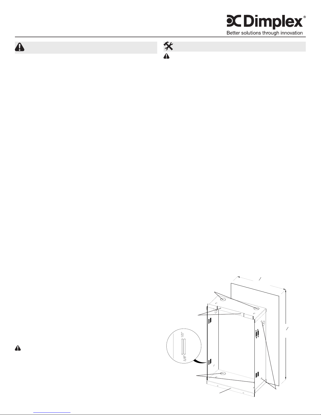
Installation Instructions
CAUTION: Place furniture/objects no closer than 3ft
(91cm) in front of the heater. Ensure that the inlet and bottom
of the heater is unobstructed to allow for sufcient air ow
through the unit.
2 x 4 Framing
1. Unpack the heater from the carton.
2. Determine the correct mounting height for the heater.
The bottom of the heater should be mounted a minimum
of 8” (20.3 cm) from the oor. The recess box is designed
so that it can be mounted between two studs within the
wall.
3. The recess box requires an opening in the wall 13.5”
(34.5 cm) high by 8 3/8” (21.5 cm) wide (see Figure
1). The depth of the opening must be 3 3/4” (9.5 cm)
minimum, measured from nished wall surface.
!
NOTE: The sides of the recess box are marked with
guidelines to allow for ½” and ⅝” drywall thickness. When
installing the recess box before installing drywall, use the
depth guidelines to mount the box at the appropriate depth
for drywall thickness, and proper grille installation.
4. Remove appropriate electrical knockout and secure sup-
ply wire using an approved strain relief connector, leaving 6” (15.2 cm) of wire leads in the recess box. (Figure
1)
!
NOTE: It is only necessary to remove the knockout that
will feed the power supply wiring, keeping in mind the heater
mounting location and supply wire location on the wall.
5. The recess box can be secured using the anges at the
top and bottom or from the inside into surrounding studs.
Ensure that the recess box is oriented so that the knockouts are located at the bottom and the anges are ush
with the nished wall.
6. Proceed to the wiring instructions.
Figure 1
Top Mounting
Holes
Front Mounting
Holes
Electrical
Knockouts
For securing Front Panel
Do not use for mounting!
3
8
"
8
(21.5 cm)
1
"
13
2
(34.5 cm)
Side Mounting
Holes
7213090100R01
Page 2
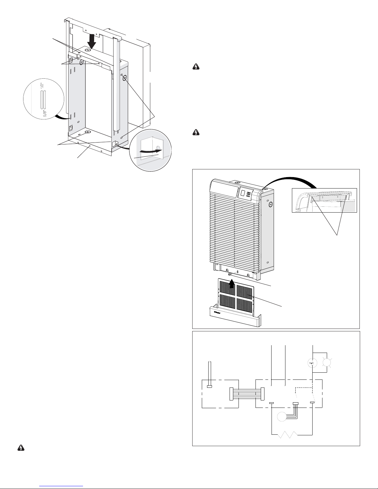
Figure 2
Top Mounting
Holes
8 3/8”
(21.5 cm)
1. Insert approximately 6” (15.2 cm) of supply wire into
recess box through the desired knockout. Wire should be
rated for a minimum of 75°C (167°F)
2. Connect power supply to terminals provided marked L1
and L2. Ground wire should be secured to green wire
Front Mounting
Holes
13 1/2”
(34.5 cm)
provided inside of the heater assembly.
WARNING: All units are factory prewired for operation
with the built-in thermostat. THIS HEATER IS NOT TO BE
USED WITH A REGULAR WALL THERMOSTAT.
3. Do a nal and complete check of all wiring.
Side
Mounting
Holes
4. Attach heater by hanging heater on upper tabs then se-
curing at the bottom using the supplied screw. (Figure 3)
5. Insert the air lter through the bottom slot, until it clicks
into place.
WARNING: TO PREVENT THE RISK OF FIRE OR IN-
Electrical
Knockouts
For securing Front Panel
Do not use for mounting!
2 x 3 Framing
Mounting
Tabs
JURY, DO NOT OPERATE THE HEATER UNLESS IT IS
FULLY ASSEMBLED.
!
NOTE: Prior to energizing remove all construction dirt
(plaster, sawdust, etc.) from interior and exterior of heater.
Figure 3
1. Unpack the heater from the carton.
2. Determine the correct mounting height for the heater.
The bottom of the heater should be mounted a minimum
of 8” (20.3 cm) from the oor. The recess box is designed
so that it can be mounted between two studs within the
wall.
3. The recess box requires an opening in the wall 13.5”
(34.5 cm) high by 8 3/8” (21.5 cm) wide (see Figure 2).
Securing Tabs
The depth of the opening must be 2 7/8” (7.3 cm). This
is measured from the nished wall surface.
4. Bend the four tabs out to secure the recess box to the
drywall.
!
NOTE: The sides of the recess box are marked with
guidelines to allow for ½” and ⅝” drywall thickness. When
Retaining Screw
installing the recess box before installing drywall, use the
depth guidelines to mount the box at the appropriate depth
Washable Filter
for drywall thickness, and proper grille installation.
5. Remove appropriate electrical knockout and secure sup-
ply wire using an approved strain relief connector, leaving 6” (15.2 cm) of wire leads in the recess box. (Figure
2)
!
NOTE: It is only necessary to remove the knockout that
will feed the power supply wiring, keeping in mind the heater
mounting location and supply wire location on the wall.
Wiring
Temperature
Sensor
L2
G
L1
Cutout
6. Slide the spacer on to the recess box so that the front
ange of the spacer is located behind the front ange of
the recess box.
!
NOTE: The bottom ends of the spacer may need to be
Display
Board
Control
Board
separated slightly to ensure it slides over the recess box
more smoothly and the ends may need to be bent in slightly
once installed to ensure proper t.
M
Motor
7. Proceed to the wiring instructions.
Supply Wiring and Heater Installation
Heater
WARNING: Wiring procedures and connections should
be in accordance with the National Electric Code (NEC &
CEC) and local codes.
2 www.dimplex.com
R
Over
Temperature
Light
Page 3

Operation
WARNING: This heater is factory prewired for operation
with the built-in thermostat. THIS HEATER IS NOT TO BE
USED WITH A REGULAR WALL THERMOSTAT.
CAUTION: This heater must be properly installed before
it is used.
The PCH is a Precision Comfort Heater, which maintains a
constant room temperature through the continuous addition
of heat by the blowing of air into the room based on the setting of the thermostat. The PCH operates such that once the
room reaches the set point, the fan and heater will continu-
ously run at a low level, to maintain the desired room temperature. If the temperature in the room rises, i.e. sun coming
through a window, the fan will slow further and the temperature of the heater will reduce so that the temperature of the
room will continue to be the same.
!
NOTE: The element retains heat after shutdown, there
is a built in cool down period of 2 ½ minutes before the fan
shuts off completely.
WARNING: Should the Over Temp light come on, discon-
nect power to the heater and call a licensed electrician.
DO NOT USE HEATER UNTIL THE CAUSE OF THE
PROBLEM IS DETERMINED AND FIXED.
Manual Controls
(See Figure 4 for display reference)
When power is rst supplied to the PCH the Setpoint Tem-
perature will ash in the temperature display area. At any
time either the ✚ or – button can be pressed to have the
temperature setpoint displayed again.
A. Setting/Temperature Display
The PCH is designed to control the temperature of a room
anywhere from 32-86°F (0-30°C). By pressing the ✚ or –
will increase or decrease the desired temperature for the
room to be heated by 0.5° (in either °C or °F).
After 5 seconds the Setpoint Temperature will switch to dis-
play the ambient temperature of the room.
!
NOTE: Pressing the ✚ and – at the same time will toggle
between °C and °F.
Figure 4
A
D
C
B
A - Setting/Temperature Display
B - Comfort Setting Icon
C - Economy Setting Icon
D - Set Back Temperature Setting
E - Synchronized Icon
F - Lock Icon
G - Decrease Button
H - Increase Button
I - Menu Button
F
E
B. Comfort Setting
The Comfort Setting icon will be displayed when the heater
is in normal operation based on the Setpoint Temperature for
the room.
!
NOTE: Either the or icon will always be visible, de-
pendent on the setting being used.
C. Economy Setting
The Economy Setting can be used to change the Setpoint
Temperature for a user determined period of time. By pressing the V the Economy Setting will be enabled - signied by
the icon ashing. After the Set Back Temperature has been
set, the icon will become solid after three seconds and the
Set Back Temperature will be enabled.
To return back to the Comfort Setting press the V button. The
icon will disappear and the icon will appear.
D. Set Back Temperature Setting
The Set Back Temperature Setting is used during periods
when the Economy setting feature is active. This temperature
adjustment can be set by pressing the V followed by the ✚
or –.
E. Synchronized Icon
The PCH features CONNEXTM, a wireless technology that
works with Dimplex single and multi-zone CONNEXTM controllers to provide simple whole home connectivity and comfort. CONNEXTM controllers are available to control one or
multiple Precision Comfort Heaters within a 50’ (15 m) radius.
In order for the controller to have this function the PCH and
the controller will need to be synchronized. To do this:
1. On the PCH heater press and hold the V button for 3
seconds, both the and icons will begin to ash.
2. Press the – , ✚ and then V, on the PCH heater.
3. Within 10 seconds press any button once on the CON-
NEXTM Controller.
!
NOTE: There is a 3 second delay between pressing the
last button on the controller and the PCH heater.
!
NOTE: To desynchronize a PCH heater from the synchronized CONNEXTM Controller; on either the PCH heater or the
controller:
1. Press and hold the V for 3 seconds.
2. Press the V, ✚ and then –.
Nothing will need to be done to the other component.
H
G
I
Dimplex single and multi-zone CONNEXTM controllers are
sold separately and are available for purchase from your
authorized Dimplex dealer.
To nd your local Dimplex dealer, visit www.dimplex.com.
F. Lock Icon
The PCH has a Lock feature to prevent settings from accidentally being changed.
1. Press and hold the V for 3 seconds. Both the and
Icons will begin to ash.
2. To Enable: Within 5 seconds press ✚, then –, then ✚,
then –. The icon will appear
3
Page 4

To Disable: Within 5 seconds press –, then ✚, then –,
then ✚. The icon will disappear.
!
NOTE: The PCH can be locked in either the Comfort or
Economy Setting. Ensure that the desired icons are present
when locking is complete.
Boost Function
The PCH is also equipped with a “Boost Function” which allows the user to run the unit at full heat, for a predetermined
amount of time, to quickly heat up a cold room/space. The
Boost can be set for a maximum of 20 minutes, in 5 minute
increments.
To enable Boost:
1. Press and hold ✚ for 5 seconds. The area where the
temperature normally displays will begin to toggle between the display of “HI” and “20”.
!
NOTE: The “20” indicates the time (in minutes) remaining
in Boost function. The timer is updated as the time counts
down 19, 18, 17, etc.
2. The length of time that Boost is enabled for can be
adjusted by pressing the ✚ or – buttons. Every time the
✚ or – button is pressed the timer will be adjusted by 5
minutes and will cycle back to 20 minutes.
3. When the timer times out the heater will return to the
programmed settings.
!
NOTE: At any time you can hold down the – button for 5
seconds and exit the Boost function.
Maintenance
WARNING: Always disconnect power at the circuit
breaker to the unit prior to performing any maintenance or
service operation.
CAUTION: Allow adequate time for the element and body
casing to cool before attempting to work on the heater.
It is suggested that the heater be inspected regularly, for
cleanliness of the air lter and fan exhaust grille, to ensure
optimal performance is maintained. Both the lter and grille
can be cleaned by:
• Vacuuming off all dust and dirt or,
• Washing the lter in warm, soapy water and allowing to dry thoroughly before reinstalling.
Once cleaning is complete replace the grille and lter, and
restore power.
!
NOTE: NEVER operate the heater without the lter and
front grille in place.
At least at yearly intervals the wire connection condition
should be inspected to ensure full electrical continuity and
optimal performance is maintained.
WARNING: The user can perform cleaning ONLY. All
other servicing should be performed by qualied service
personnel.
Warranty
The Manufacturer warrants the linear convector and
components of the enclosed product against any defect
in material or workmanship for a period of two years from
the date of purchase, with the exception of the elements
which are warranted to be free from defect in material and
workmanship for ve years. In full satisfaction of any claims
under this Warranty the Manufacturer will repair or replace
without charge, in its factory or in the eld as it alone may
decide, any parts which in its opinion are defective.
The Manufacturer shall not be responsible for any
transportation or shipping costs in relation to such repair
or replacement except as specically assumed by it.
Misuse of this product or repairs by persons other than
the Manufacturer’s authorized personnel without the
Manufacturer’s written approval, will void this Warranty.
This Warranty is in lieu of all other warranties or conditions
whether expressed or implied including but not limited to
those of merchantability or tness for purpose and shall
constitute the sole remedy of the Purchaser and the sole
liability of the Manufacturer in respect of the sale of the
product, whether in the nature of breach or breach of
fundamental term, or of negligence or otherwise.
The Manufacturer shall not be liable for any special, indirect
or consequential damages or for any damages resulting from
removal or replacement of a heater subject to warranty claim
without the Manufacturer’s authorization.
This Warranty is transferable by the original consumer
purchaser of the product. Any claims under this Warranty
must be submitted in writing to the Service Manager, Dimplex
North America Ltd., 1367 Industrial Rd., Cambridge, Ontario
N1R 7G8, Canada.
Replacement Parts
Filter ................................0441050100RP
Blower Blade .........................5300270100RP
Blower Motor .........................2000410100RP
Power Board .........................3000980100RP
Display Board ........................3001040100RP
2000W Element .......................2203550200RP
Front Grille ...........................1024710100RP
Spacer ..............................1026500100RP
Optional Accessories
Surface Mount Box .........................PCHSBW
CONNEXTM Controllers
Single Controller ....................... DPCRWS
Multi-zone Controller .................... CX-MPC
1367 Industrial Road Cambridge ON Canada N1R 7G8
1-888-346-7539 www.dimplex.com
In keeping with our policy of continuous product improvement, we reserve the right to make changes without notice.
© 2014 Dimplex North America Limited
 Loading...