

Page 1
Service manual
2020
Service_Handboek_2020_EN.indd 1Service_Handboek_2020_EN.indd 1 29/11/19 09:2729/11/19 09:27
Page 2
Content
Content .......................................................................................................................................................................2
Introduction .................................................................................................................................................................2
This service manual .....................................................................................................................................................3
General Information for all Dimplex heating products ...................................................................................................4
Installing an electric re ...............................................................................................................................................4
Calculate the correct ventilation opening .....................................................................................................................5
Explanation of the dierent technologies. ....................................................................................................................6
Opti-Virtual ..................................................................................................................................................................6
Opti-V diagnostics and repair ......................................................................................................................................8
Optiame .....................................................................................................................................................................9
Revillusion .................................................................................................................................................................11
Optimyst (Fire from water) .........................................................................................................................................13
First Generation Optimyst (introduced in 2009) .........................................................................................................15
Second Generation Optimyst (introduced in 2012).....................................................................................................16
Third Generation Optimyst (introduced in 2015) ........................................................................................................18
Third Generation and error codes; Commercial only ..................................................................................................23
Pairing the Bluetooth Eco Remote .............................................................................................................................24
Remote control overview ...........................................................................................................................................25
Optimyst diagnostics and repair .................................................................................................................................25
Glen Dimplex
The Dimplex brand is part of Glen Dimplex Consumer Appliances Europe. They manufacture electric res. Our
company is part of the Irish Glen Dimplex Group. Worldwide, the Glen Dimplex Group is the largest manufacturer
of electric res and stoves and currently it is one of the largest suppliers of small domestic appliances. The Glen
Dimplex Consumer Appliances Europe site is located in Heerenveen in the Netherlands.
- 2 -
Although Dimplex res are electric, they oer more by creating the illusion of a life-like re - from a fascinating ame
eect, glowing logs and the crackling sounds of wood to little sparks that seem to y. A re adds to the atmosphere
and brings calm and cosiness.
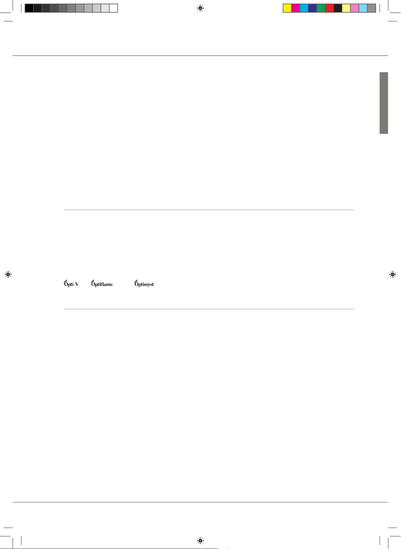
Dimplex is a leading manufacturer of attractive electric res, and has many unique designs to its name, such as the
, the and the technology.
This service manual
This service manual provides you with information about the Dimplex electric res in general, about troubleshooting
and locating defective parts. It is a supplement to the installation manual that comes with the individual products.
Read the installation manuals of the supplied product carefully.
TARGET AUDIENCE
The service manual is intended for installers who assemble, carry out maintenance and resolve faults on electric
products.
REQUIREMENTS
✔ Completed Glen Dimplex training
✔ Knowledge of the products
✔ Knowledge of installation
✔ Knowledge of the applicable standards and guidelines
✔ Certied electrician
✔ Have the right tools
✔ Disconnect from 230V before opening the product
Note: Glen Dimplex cannot be responsible for any damage caused by the repair
CUSTOMER SERVICE
If this service manual did not provide satisfactory assistance, Dimplex is pleased to help you resolve malfunctions and
handle complaints. You can also contact us for technical support.
service@glendimplex.eu
Phone: +31 (0)513 656 500
Success with this service manual
Glen Dimplex Support team
Service_Handboek_2020_EN.indd 2Service_Handboek_2020_EN.indd 2 29/11/19 09:2729/11/19 09:27
Page 3

General Information for all Dimplex heating products
IMPORTANT:
For all repairs, the products have to be disconnected from 230V before they are opened. The products
can only be serviced by adequately trained electro technical personnel.
REMOTE CONTROLS ARE INFRARED OR BLUETOOTH
Infrared: Remotes need to point in the direction of the re and will work at a distance of 10 metres.
HOW TO CHECK IF YOUR REMOTE CONTROL WORKS.
Use the camera method
Most remote controls use infrared light to transmit the signal. The human eye is not able to see this light,
but a camera can easily spot it.
So, 4 easy steps to see whether your remote is transmitting signals or not
1. Turn your phone or digital camera on
2. Point the remote control at the camera and press any button on the remote
3. If you see a blueish light come from the remote when viewed through your phone or display, then the
remote seems to be working ne
4. If you do not see a ickering blueish light or very dim… most likely it is time to replace the batteries in
the remote control with the new ones
Note:
• On some of the latest iPhones and Android phones, you’ll have to use the front camera to do this test.
Most of the rear-side cameras have IR lters that don’t sense the infrared rays anymore.
• Aware: this can only be used for infrared remotes.
Bluetooth: Remotes need to be within a 5 metres radius without the signal being blocked by concrete
walls.
Replace batteries annually to guaranty a trouble-free performance.
All products carry the IP20 certicate (only covers dust).
Do not install products in Chlorine environment.
Note: Chlorine will irreparably damage plastic materials and electronics.
FIRE SURFACE CLEANING
Use only a soft cloth to clean glass and painted surfaces of the re.
Note: Do not use abrasive cleaners.
Installing an electric re
INSTALLATION LOCATION
✔ Stable and clean surface
✔ Dust-free environment (Construction site)
✔ Provide an accessible earthed 230 Volt power outlet
✔ All products can be built in ammable materials
✔ Observe the required ventilation requirements
✔ Optimyst products must be installed spirit level (at)
- 3 -
Service_Handboek_2020_EN.indd 3Service_Handboek_2020_EN.indd 3 29/11/19 09:2729/11/19 09:27
Page 4
General Information for all Dimplex heating products
VENTILATION
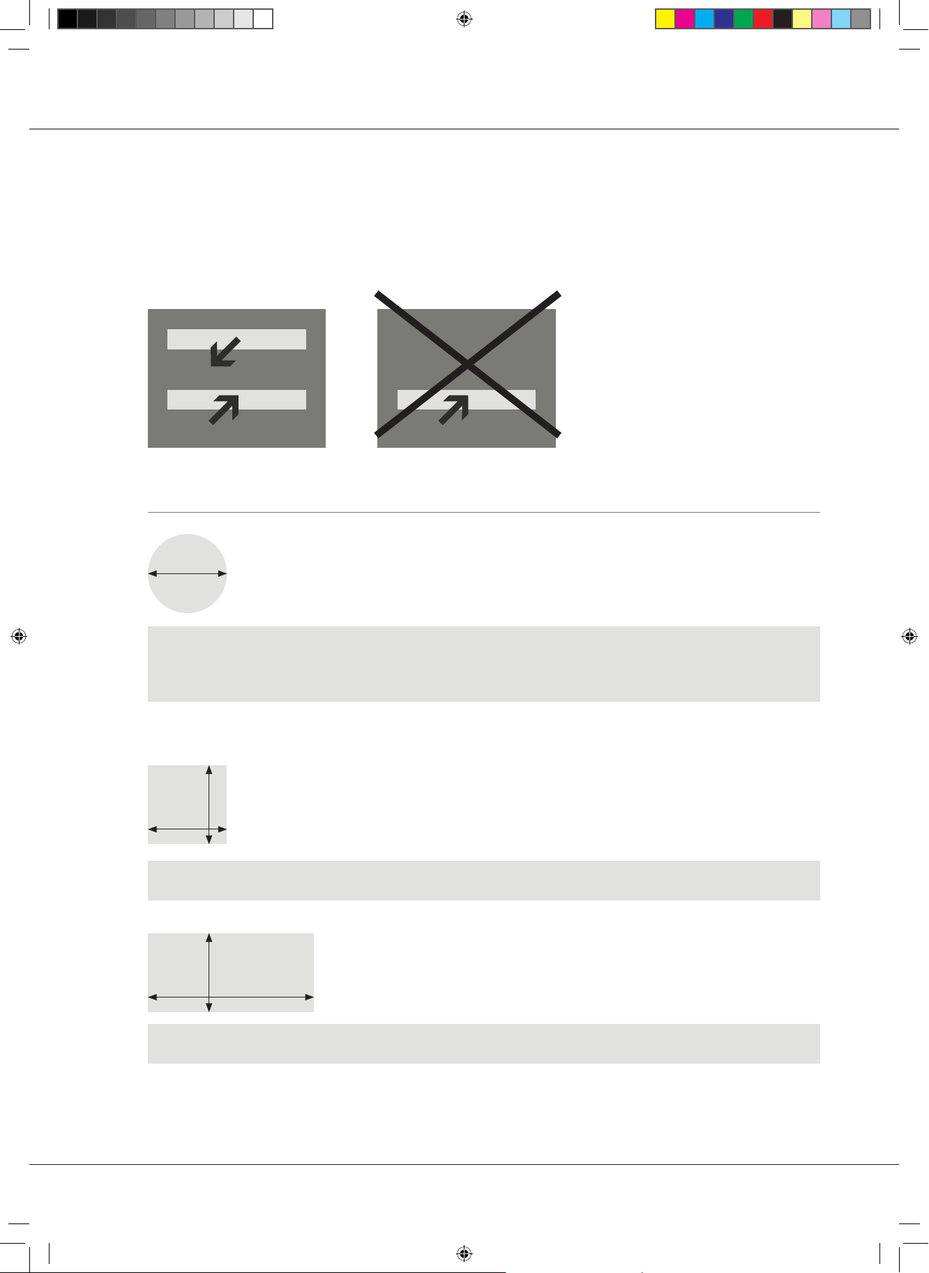
All built-in appliances require ventilation for proper operation.
To create draught you always need two openings with a dierence in height, only then will there be a
natural draught of fresh air.
OUT
- 4 -
IN
IN
Correct way to ventilate Incorrect way to ventilate
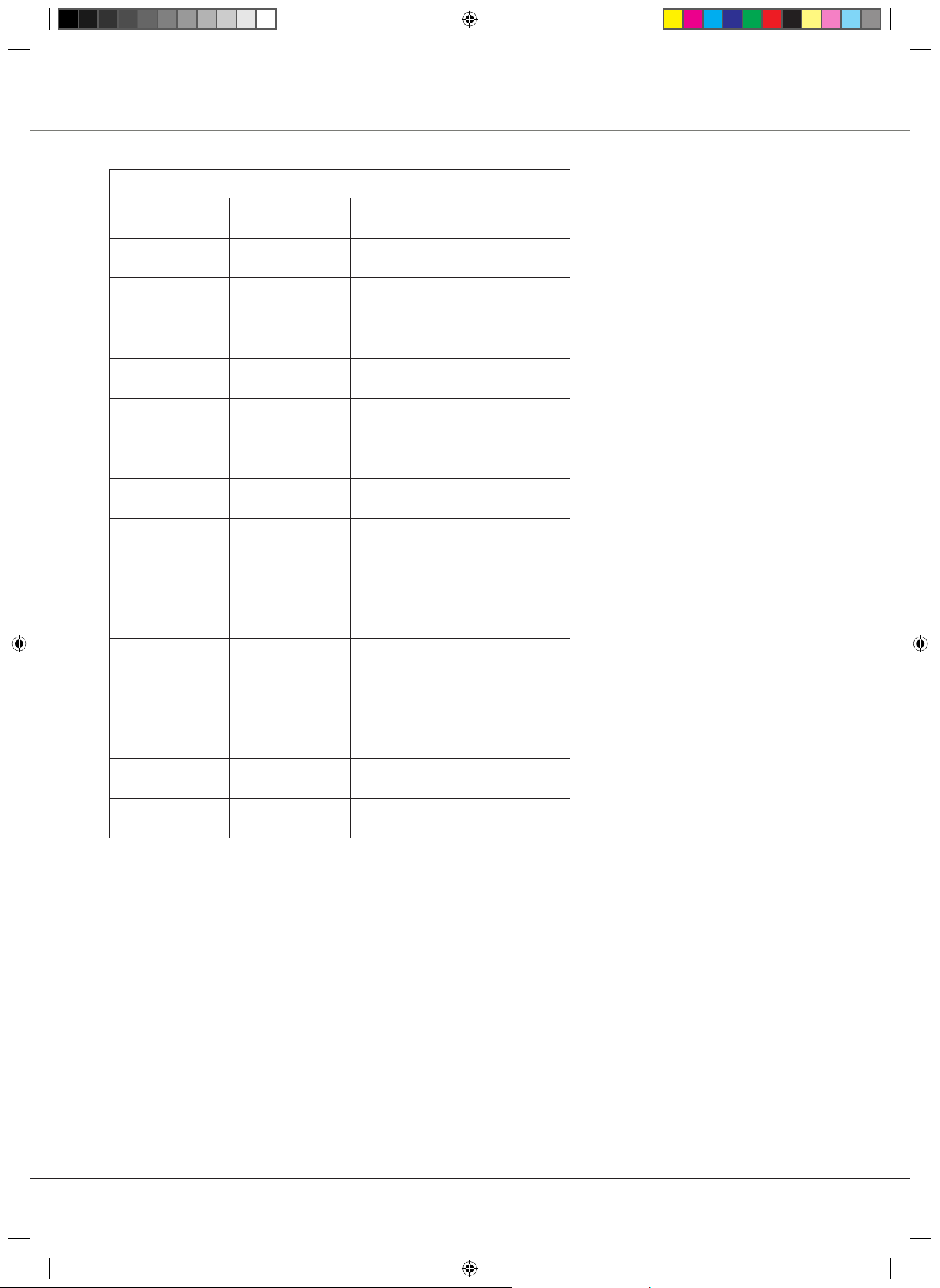
Calculate the correct ventilation opening
10cm
The diameter is 10cm
Divide the diameter by two = 10: 2 = 5cm
Radius x radius x PI = 5 x 5 x 3.14 = 78.50cm
When request 210cm you need 3x opening of ∅ 10cm = 235.5cm2
When request 420cm you need 6x opening of ∅ 10cm = 471cm
10cm
10cm
2
2
length x width 10 x 10 = 100cm
10cm
21cm
length x width 21 x 10 = 210cm
2
2
Note:
Optimyst products without ventilation will become damaged irreparably after a short period of time. This
will never be covered by the Dimplex warranty.
Service_Handboek_2020_EN.indd 4Service_Handboek_2020_EN.indd 4 29/11/19 09:2729/11/19 09:27
Page 5
REQUIRED VENTILATION PER PRODUCT
General Information for all Dimplex heating products
Opti-V Single 100cm
2
Opti-V Double 200cm2
Optiame 100cm
Revolution 100cm
Optimyst Cassette 250 100cm
Optimyst Cassette 400 200cm
Optimyst Cassette 600 200cm
2
2
2
2
2
Optimyst Cassette 500 (Retail and Commercial) 210cm
Optimyst Cassette 1000 (Retail and Commercial) 420cm
Optimyst Cassette L Pebbles 220cm²
Optimyst Juneau 210cm
2
2
2
Optimyst Juneau XL 220cm
Optimyst Engine 56-400 200cm
Optimyst Engine 68-400 200cm
Optimyst Engine 56-600 MB 200cm
Optimyst Engine 56-400 B 200cm
2
2
2
2
2
- 5 -
Service_Handboek_2020_EN.indd 5Service_Handboek_2020_EN.indd 5 29/11/19 09:2729/11/19 09:27
Page 6
Explanation of the dierent technologies
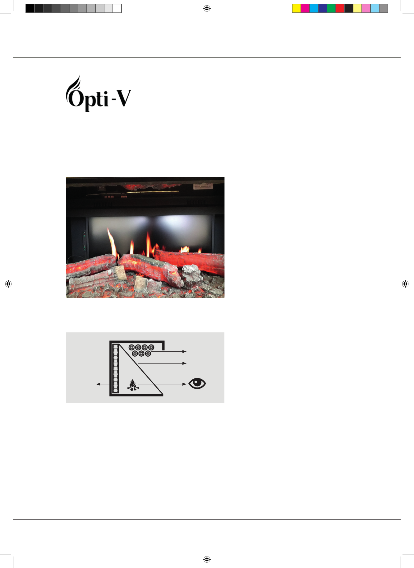
Every re with Dimplex Opti-Virtual® technology uses the latest HDTV technologies to produce its re
eect. The ame eect is on an SD card and shown on an HD TV screen.
With a remote control you can regulate the re On/O ame eect and sound.
HOW TO IDENTIFY OPTIV TECHNOLOGY
- 6 -
HOW IT WORKS
SD Card
Log set
Transparent
mirror foil
HD
TV screen
Service_Handboek_2020_EN.indd 6Service_Handboek_2020_EN.indd 6 29/11/19 09:2729/11/19 09:27
Page 7
Explanation of the dierent technologies
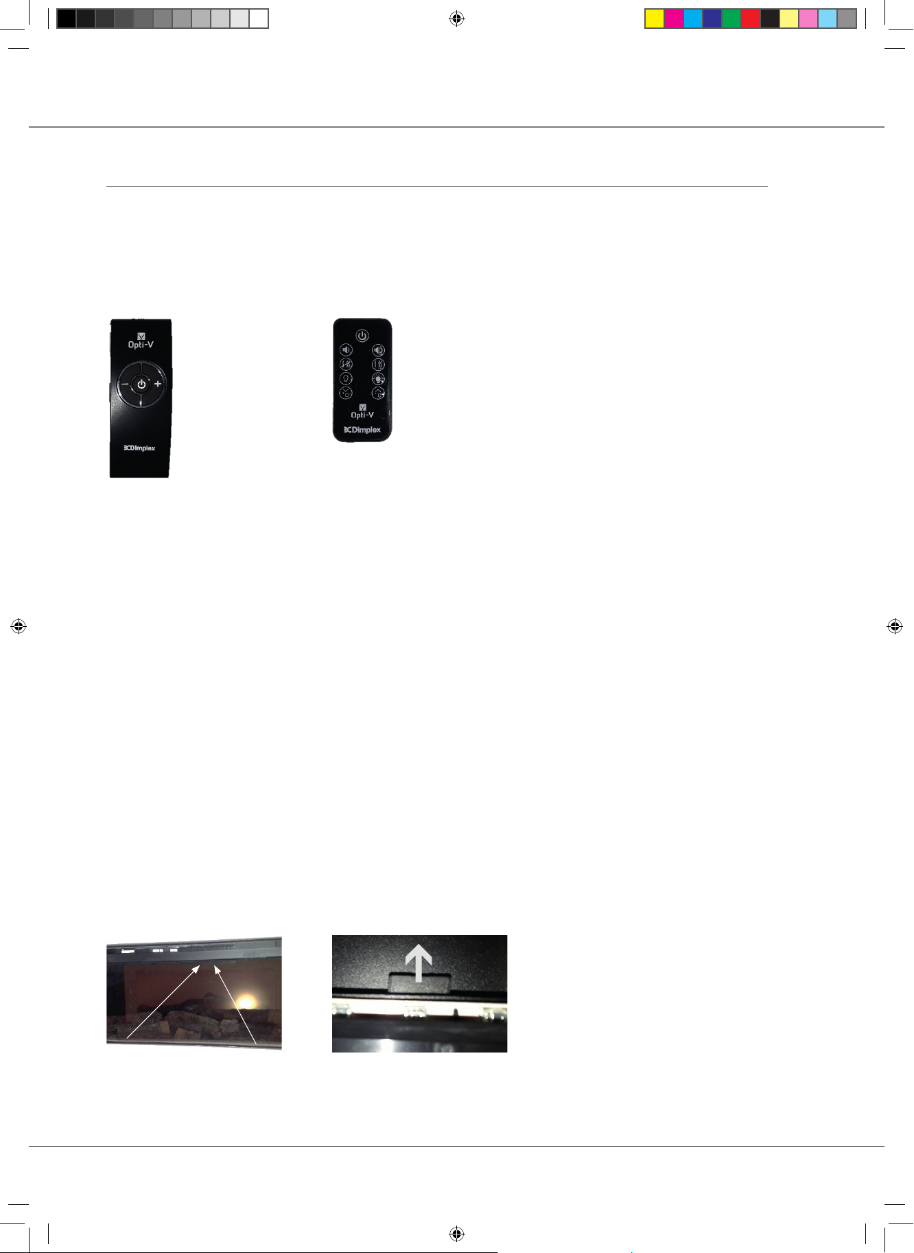
Remote control with infrared technology and basic functions
The remote control may be operated once the appliance is switched to ‘I’.
A red light will indicate when the appliance is in standby mode. Point the remote control at the screen
(at the infrared sensor). The audio volume may be adjusted up or down by pressing the volume control
buttons (+ and -).
REMOTE CONTROL:
Built-in Freestanding
BASIC CHECKS FOR OPTIV TECHNOLOGIES
• Remote will only work when the On/O switch of the appliance is in the “I” position
• Has the SD card been tted correctly and check the latest version number of the SD card
• Check 230V connection – check socket if needed and measure 230V
• Check the fuse of the power supply in that room
• Check the battery of the remote
MANUAL CONTROL OPERATION, FOR THE BUILTIN PRODUCT
• The manual controls for the screen and sound are located at the inner top left side of the appliance
above the glass
• There is a power switch, a stand-by button and light adjustment buttons
MANUAL CONTROL OPERATION FOR THE SCREEN AND SOUND, FOR THE FREESTANDING PRODUCT
• Opti-V 360: On/o is on the back
• Sunningdale: Behind the door
RATING LABEL
The series number of the product can be found on the label on the right hand side of the product above
the glass.
SD CARD POSITION
• Single and Double cassette
See gure
- 7 -
SD Card Rating Label Pull SD card out
Service_Handboek_2020_EN.indd 7Service_Handboek_2020_EN.indd 7 29/11/19 09:2729/11/19 09:27
Page 8

Explanation of the dierent technologies
• Sunningdale:
Access at the back of the appliance
• Opti-V 360°
The SD card is behind the front panel of the 360. You have to remove the screws on the sides to take
o the front panel.
ACCESS TO THE ELECTRONICS
1. Access to components from the front
2. Remove glass by unscrewing the metal lid
3. Gently slide the glass out and place it safely and protect it against falling over
4. Remove the log bed
5. Remove the screws to take the TV screen out
6. Open the back to have access to the electronics
Front view of Opti-V single cassette with suction cup to slide out the front panel
1 2
- 8 -
Remove the log bed
✘ Position of the screws
REQUIRED VENTILATION OPENINGS
100cm2 Single
200cm2 Double
Opti-v diagnostics and repair
More extensive technical information in the Opti-V diagnosis manual
Available on request: 40011924 OPTI-V DIAGNOSTICS AND REPAIR
Service_Handboek_2020_EN.indd 8Service_Handboek_2020_EN.indd 8 29/11/19 09:2729/11/19 09:27
Page 9
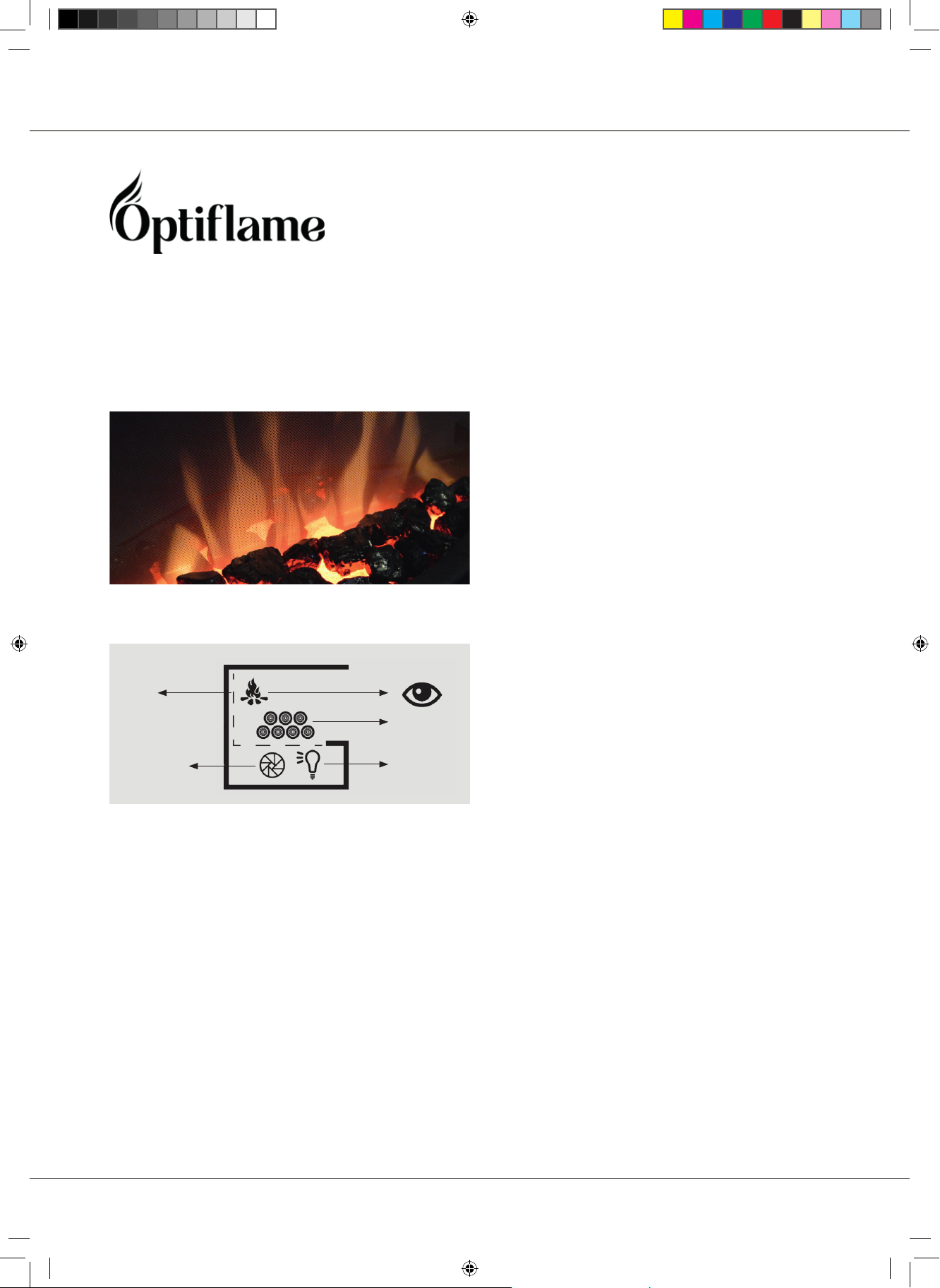
Flame projection on glass, based on light reection from LEDs
Rotisserie shaft and rotisserie motor 10 or 15 rpm
Infrared remote control with on/o function
Some products have a dimmer function and LED lights in the log set
HOW TO IDENTIFY OPTIFLAME TECHNOLOGY
All products have a front panel
Explanation of the dierent technologies
HOW IT WORKS
Mirror
Decoration
Log set
Alu Roterie
LED lights
REMOTE WITH INFRARED TECHNOLOGY AND BASIC FUNCTIONS
The re is supplied with an infrared multifunction remote control.
NOTE: To operate correctly, the remote control must be pointed at the display.
BASIC CHECKS FOR OPTIFLAME TECHNOLOGY
• Remote will only work when the On/O switch of the appliance is in the “I” position
• Check 230V connection – check socket if needed and measure 230V
• Check the fuse of the power supply in that room
• Check the battery of the remote
MANUAL CONTROL OPERATION
The manual controls for the ame eect are located behind the door at the front
- 9 -
Service_Handboek_2020_EN.indd 9Service_Handboek_2020_EN.indd 9 29/11/19 09:2729/11/19 09:27
Page 10

Explanation of the dierent technologies
RATING LABEL
Model and serial numbers can be found on the back of the product
TROUBLESHOOTING
Most common,
• Heating element – replacement
• Motor – replacement
• Rotisserie noise – position and greasing
- 10 -
Service_Handboek_2020_EN.indd 10Service_Handboek_2020_EN.indd 10 29/11/19 09:2729/11/19 09:27
Page 11

Flame projection on glass, based on light reection from LEDs
Rotisserie shaft and rotisserie motor 10 or 15 rpm
Infrared remote control with on/o function
Some products have a dimmer function and LED lights in the log set.
HOW TO IDENTIFY REVILLUSION TECHNOLOGY
There is no front panel on the Revillusion
Explanation of the dierent technologies
HOW IT WORKS
Mirage ame
panel
Brick wall
Rotisserie
Decoration
Log set
LED lights
REMOTE WITH INFRARED TECHNOLOGY AND BASIC FUNCTIONS
The re is supplied with an infrared multifunction remote control.
NOTE: To operate correctly, the remote control must be pointed at the display.
BASIC CHECKS FOR REVILLUSION TECHNOLOGY
• Remote will only work when the On/O switch of the appliance is in the “I” position
• Check 230V connection – check socket if needed and measure 230V
• Check the fuse of the power supply in that room
• Check the battery of the remote
MANUAL CONTROL OPERATION
• The manual control touch panel is located at the front
• The heating can be switched o with software
- 11 -
Service_Handboek_2020_EN.indd 11Service_Handboek_2020_EN.indd 11 29/11/19 09:2729/11/19 09:27
Page 12

Explanation of the dierent technologies
REMOTE CONTROL
Revillusion re box Log set basket
Please note: Heating function only by remote for both products
RATING LABEL
Model and serial numbers can be found on the back of the product
- 12 -
TROUBLESHOOTING
Most common,
• Heating element – replacement
• Motor – replacement
• Rotisserie noise – position and greasing
• Dust on the back of the Mirage panel
Service_Handboek_2020_EN.indd 12Service_Handboek_2020_EN.indd 12 29/11/19 09:2729/11/19 09:27
Page 13

Explanation of the dierent technologies
(Fire from water)
Optimyst is a combination of light and water mist that can be enough to see “ames”.
With the Optimyst you have full access to the cold ame.
HOW TO IDENTIFY OPTIMYST TECHNOLOGY
HOW IT WORKS
Decoration
Log set
Water vapour
Transducer
Halogen or
LED lights
with 200W
heating
An ultrasonic mist generator creates vapour in a water sump, and when this is combined with light it
produces a ame eect.
MOST IMPORTANT PREREQUISITES
• Ventilation
• Water quality
Use only clean and decalcied water
• Normal tap water will have scale
• Scale will damage the performance of the product after a very short period of time
• Maintenance
- 13 -
Service_Handboek_2020_EN.indd 13Service_Handboek_2020_EN.indd 13 29/11/19 09:2729/11/19 09:27
Page 14

Explanation of the dierent technologies
THE FOLLOWING PARTS MUST BE CLEANED EVERY 2 WEEKS, PARTICULARLY IN AREAS WITH
HARD WATER.
Water tank, sump, nozzle, tank cap with seal and air lter.
Please use the supplied brush for cleaning!
- 14 -
FIRE SURFACE CLEANING
Use only a soft cloth to clean glass and painted surfaces of the re.
Note: Do not use abrasive cleaners.
THERE ARE THREE GENERATIONS OF OPTIMYST PRODUCTS
1. First generation Optimyst (introduced in 2009)
2. Second generation Optimyst 2012
3. Third generation Optimyst 2015
BASIC CHECKS FOR ALL OPTIMYST TECHNOLOGY
• The required ventilation opening
• Remote will only work when the On/O switch of the appliance is in the “I” position
• Check 230V connection – check socket if needed and measure 230V
• Check the fuse of the power supply in that room
• Check the battery of the remote
• Check if the transducer is working
• Do not use any oil to create an aroma eect in any Optimyst product
Service_Handboek_2020_EN.indd 14Service_Handboek_2020_EN.indd 14 29/11/19 09:2729/11/19 09:27
Page 15

Explanation of the dierent technologies
First Generation Optimyst (introduced in 2009)
Equipped with a sump, which holds the transducer, and 45 Watt halogen lamps, access through a drawer
with the sump and lamps.
Infrared remote control with on/o function.
Heating option in selected models.
Sump
Flame height can be adjusted by adjusting the speed of the fan.
REMOTE WITH INFRARED TECHNOLOGY AND BASIC FUNCTIONS
The re is supplied with an infrared multifunction remote control.
NOTE: To operate correctly, the remote control must be pointed at the appliance display.
- 15 -
Without heat for cassette
products
Service_Handboek_2020_EN.indd 15Service_Handboek_2020_EN.indd 15 29/11/19 09:2729/11/19 09:27
Eco remote for built-in
products
Page 16

Explanation of the dierent technologies
RATING LABEL
Model and serial numbers can be found behind the drawer or on the back of the product.
COMMON FAILURES
• Transducer needs to be replaced regularly (Replace the sump)
• Fan is not running (check the correct size of the ventilation opening)
- Insucient ventilation due to incorrect installation see page…..
• Broken wiring caused by the drawer
• Defective lamps are not replaced by the end user, produce less upward draft and condensation
• Water tank leakage.
- Closure of the water tank. Result: No water!
Closure of the
water tank
- 16 -
Second Generation Optimyst (introduced in 2012)
CHANGES
The most important change is the separately replaceable transducer.
Electronics technology is accessible through a removable log set, which means there is no drawer
anymore and the ame height can be adjusted by adjusting the speed of the fan.
CONTROL PANEL AND REMOTE
Flame height Standby ame Mains on/o
Service_Handboek_2020_EN.indd 16Service_Handboek_2020_EN.indd 16 29/11/19 09:2729/11/19 09:27
Page 17

Explanation of the dierent technologies
REMOTE CONTROL
Freestanding Without heat cassette Eco remote with heat
for built-in products
COMMON FAILURES
• Transducer needs to be replaced regularly
• Fan is not running (check the correct size of the ventilation opening)
- Insucient ventilation due to incorrect installation see page…..
• Defective lamps are not replaced by the end user, produce less upward draft and condensation
• Water tank leakage.
- Close o the water tank. Result: No water!
Seal ring not in the right place Seal ring positioned correctly place
Check the water tank for leakage
- 17 -
Service_Handboek_2020_EN.indd 17Service_Handboek_2020_EN.indd 17 29/11/19 09:2729/11/19 09:27
Page 18

Explanation of the dierent technologies
Third Generation Optimyst (introduced in 2015)
THE MOST IMPORTANT CHANGES:
COMMERCIAL VERSION PROJECTS RETAIL VERSION
- 18 -
✔ Fixed connection to the water supply
✔ Error codes
✔ Double transducer pro motor
✔ Connect one remote for multiple appliances
✔ LED lights
✔ An added heating element provides upward air
✔ Adjustable ame height in 6 steps
✔ Remote control via Bluetooth
✔ Crisper wood re sound
✔ Detachable wood set with LED lights (accessory)
CONTROL PANEL AND REMOTE:
On board controls
✔ Water bottle operation
✔ Connect one remote for multiple appliances
✔ LED lights
✔ An added heating element provides upward air
✔ Adjustable ame height in 6 steps
✔ Remote control via Bluetooth
✔ Crisper wood re sound
✔ Detachable wood set with LED lights (accessory)
Bluetooth receiver
Remote control
Flame controls (master side)
Flame controls (slave side)
CONNECT REMOTE TO MULTIPLE APPLIANCES
1. Pair the rst product
2. Second product, press the rocker switch to the on (I) position; a single beep will be heard
3. Press the standby button on the Button Panel; the product will switch on
4. Press the Bluetooth button on the Button Panel, the LEDs will start to blink slowly
5. Press the sound button on the remote control; the LEDs will ash quickly three times and the product
will then automatically switch o. The remote control is now paired to the two products
6. Repeat the above steps to pair the next product
Service_Handboek_2020_EN.indd 18Service_Handboek_2020_EN.indd 18 29/11/19 09:2729/11/19 09:27
Page 19

TEST PROGRAM
1 2 3 4 5 6 7
Main switches in the on position (product is in standby).
Push test mode button 3 to activate test mode.
TEST NO. TEST MODE FUNCTION
1 Button 7 Turns on the main leds
2 Button 6 Turns on the sound
3 Button 5 Turns on the transducer
Explanation of the dierent technologies
4 Button 4 Turns on the fan
5 Button 3 Turns on the solenoids (magnetic valve)
6 Button 2
7 Button 1 Turns on power to the fuel bed
Turns on the element.(Click sound should be heard and the reading on the clare
test box is between 1.7A – 2a)
Note: Product will leave test mode after 10 seconds without pushing a button.
Main water connection: Commercial only
Minimum water pressure is 0.5 bar
Maximum water pressure is 8 bar
- 19 -
Service_Handboek_2020_EN.indd 19Service_Handboek_2020_EN.indd 19 29/11/19 09:2729/11/19 09:27
Page 20

Explanation of the dierent technologies
COMMON FAILURES
• Insucient ventilation due to incorrect installation
• Conduction or water leak (Aqua stop blocks water supply, pill must be replaced) (commercial only)
• Maintenance
• Transducer needs to be replaced regularly
• Fan is not running (check the correct size of the ventilation opening)
- Insucient ventilation due to incorrect installation see page…..
• Water tank leakage
- Close o the water tank. Result: No water!
Aqua stop open will switch
o the appliance
Pill grown 4 times in volume
due to moisture
- 20 -
RECOGNISE THE CORRECT WATER LEVEL
Water level must be between these two marks
in the sump.
THIRD GENERATION, HOW WE MANAGE THE WATER LEVEL
The water level is regulated by a reed contact.
(A reed contact or reed switch is an electrical switch contact in a glass tube that is operated by a
magnetic eld.)
How does it work in an Optimyst:
Magnets oat in the sump and follow the water level and thus operate a switch contact.
The taller left moulding contains the min and overow reed switches. The smaller right moulding contains
the max reed switch.
Overow is the highest (top left), then max (top right), then min (bottom left).
Note: The left switch has a 2-way connector, while the right switch only has a 1-way.
See gure
Service_Handboek_2020_EN.indd 20Service_Handboek_2020_EN.indd 20 29/11/19 09:2729/11/19 09:27
Page 21

Explanation of the dierent technologies
TRANSDUCER
Note:
• There will be a tolerance between the amount of myst a transducer can produce
• When the myst is getting lower, clean or replace the transducer
Transducer water sensor
Left-hand-thread
Transducer disc
Myst maximize is only used on the products below:
1. Cassette 500, 1000 (retail & commercial)
2. Cassette 400 LED
Connecting cable Transducer myst maximize
Transducer
- 21 -
Service_Handboek_2020_EN.indd 21Service_Handboek_2020_EN.indd 21 29/11/19 09:2729/11/19 09:27
Page 22

Explanation of the dierent technologies
Third Generation and error codes; Commercial only
1 ash – 8 seconds pause – 1 ash Too much water
• Water bottle: check closure of water bottle is tted correctly; check for leaks or holes in water bottle.
• Permanent water lling: check water connection to the product; does water ow into the product in the o
position; if so, ush magnetic valves
• Empty the sump. Restart the product
2 ashes – 8 seconds pause – 2 ashes Not enough water
• Water bottle: rell water bottle
• Permanent water lling: check water ow; eventually raise water pressure (max 8bar / ~2,5l/min); water level be
over min limit within 20 seconds from start
• Restart product
3 ashes – 8 seconds pause – 3 ashes Signal cannot be interpreted
• Check oats for correct t; has to have same level; check that oats are not trapped/jammed
• Restart product
- 22 -
4 ashes – 8 seconds pause – 4 ashes Water does not ll quickly enough
• After 90 seconds oats have to reach max limit
• Water bottle: check closure of water bottle is tted correctly ; check for leaks or holes in water bottle
• Permanent water lling: check water ow; eventually raise water pressure (max 8bar); water level must be over
minimum limit within 20 seconds from start
• Eventually pre-ll the sump. Restart product
Service_Handboek_2020_EN.indd 22Service_Handboek_2020_EN.indd 22 29/11/19 09:2729/11/19 09:27
Page 23

Explanation of the dierent technologies
Pairing the Bluetooth Eco Remote
• Bluetooth (RC) connection (not infrared)
• Works within a range of 5 meter
• While in pairing mode, the transmitting power is reduced in order not to connect with any other
device
• In pairing mode, the remote has to be very close to the product to pair (centimetres)
REMOTE CONTROL
Display screen
‘Menu’ button
‘Back’ button
‘Advance’ button
‘Up and down’ arrows
‘Enter’ button
- 23 -
Points of pairing
Hold the remote control here if new
pairing is necessary
Hold it close to the electronics!
Wait e few seconds
Engines, 3step, Albany Wall re engine
Service_Handboek_2020_EN.indd 23Service_Handboek_2020_EN.indd 23 29/11/19 09:2729/11/19 09:27
Page 24

Explanation of the dierent technologies
PAIRING WHEN CONNECTION WITH EXISTING REMOTE CONTROL
OR NEW REMOTE CONTROL IS LOST REPLACEMENT
1. Switch OFF the appliance with O/I switch
2. Activate the remote control with “Enter” button
3. Remote searches for the appliance
4. Hold “Back” and “Advance” button for 5 – 8 seconds
5. “PAIR” appears on the remote control (do not hold too long, otherwise test & eolt mode will be
activated)
6. Switch on appliance and hold remote close to the appliance (see point of pairing/wait a few seconds)
7. Remote connects, light ashes, conrm with “Enter” button
Repeat if this failed
*Please check that you are holding the remote close enough to the appliance
OPTIMYST DIAGNOSTIC AND REPAIR
More extensive technical information in the Optimyst diagnosis manual
Available on request:
40011923
SERVICE INSTR. MANUAL CASS. 500/1000
Focused on Commercial
- 24 -
Service_Handboek_2020_EN.indd 24Service_Handboek_2020_EN.indd 24 29/11/19 09:2729/11/19 09:27
Page 25

Remote control overview
Optiame Optimyst Opti-virtual
Remote control overview
Viotta and
MiniMozart models
Toluca de Luxe
Firebox remotes
dier according
specications of the
products
Revillusion and Ignite
models
Suites
Cassette remotes
dier in functionality
Silverton
Engines
Sunningdale stover,
same shape for 360°
with fewer buttons
Cassettes – single,
double, Aquarium
- 25 -
HOW TO CHECK IF YOUR REMOTE CONTROL WORKS
Use the camera method
Most remote controls use infrared light to transmit the signal. The human eye is not able to see this light,
but a camera can easily spot it.
So, 4 easy steps to see whether your remote is transmitting signals or not
1. Turn your phone or digital camera on
2. Point the remote control at the camera and press any button on the remote
3. If you see a blueish light come from the remote when viewed through your phone or display, then the
remote seems to be working ne
4. If you do not see a ickering blueish light or very dim… most likely it is time to replace the batteries in
the remote control with the new ones
Note:
• On some of the latest iPhones and Android phones, you’ll have to use the front camera to do this test.
Most of the rear-side cameras have IR lters that don’t sense the infrared rays anymore.
• Aware: this can only be used for infrared remotes.
Service_Handboek_2020_EN.indd 25Service_Handboek_2020_EN.indd 25 29/11/19 09:2729/11/19 09:27
Page 26

- 26 -
USEFUL:
Netherlands:
https://www.dimplex-res.eu/voor-dealers/
Germany:
https://www.dimplex-res.eu/voor-dealers/?lang=de
English:
https://www.dimplex-res.eu/voor-dealers/?lang=en
French:
https://www.dimplex-res.eu/voor-dealers/?lang=fr
Polish:
https://www.dimplex-res.eu/voor-dealers/?lang=pl
Dimplex Experience Centre (DEC)
Feuerweg 22
D-90518 Altdorf bei Nürnberg
Tel.: +49 922 17009624
Fax: +49 922 1709924624
E-Mail: sales@glendimplex.de
Service_Handboek_2020_EN.indd 26Service_Handboek_2020_EN.indd 26 29/11/19 09:2729/11/19 09:27
Page 27

Service_Handboek_2020_EN.indd 27Service_Handboek_2020_EN.indd 27 29/11/19 09:2729/11/19 09:27
Page 28

Glen Dimplex
Consumer Appliances Europe
EU Flame
Saturnus 8 – NL-8448 CC Heerenveen
PO Box 219 – NL-8440 AE Heerenveen
T. +31(0)513 656500
Proud brand of
F. +31(0)513 656501
E. info@glendimplex.eu
Service_Handboek_2020_EN.indd 28Service_Handboek_2020_EN.indd 28 29/11/19 09:2729/11/19 09:27
 Loading...