

Page 1
INSTRUCTIONS FOR FITTING
OPTIONAL FLOOR STANDING FEET
MODELS: WMX/S718N, WMX/S724N, HSX/DA18N & HSX/DA24N ONLY
These feet should only be used when it is not intended to fix the appliance to the wall.
NOTE :- When the feet have been fitted, the appliance MUST be positioned against a wall on
a firm surface before building in the storage heater bricks.
DO NOT A TTEMPT TO MOVE THE HEA TER, UNDER ANY CIRCUMST ANCES, ONCE
THE BRICKS ARE FITTED
CONTENTS TOOLS REQUIRED
2 x Floor Standing Feet Pozi-drive Screwdriver
4 x No. 6 x 3/8” Self Tapping Screws Electric Drill
2 x M4 Taptite Screws
1 x 2.6mm Ø drill bit
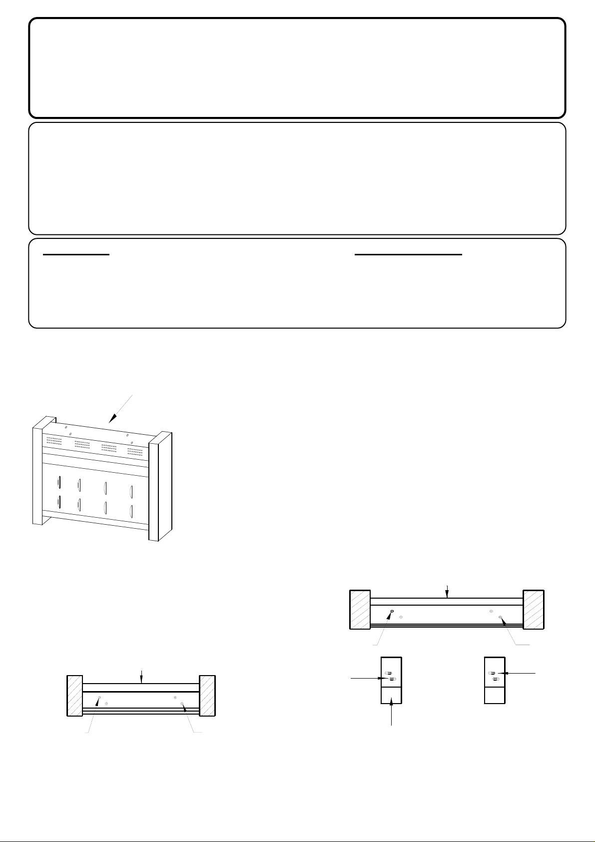
1. Remove the outer wrap packing of the heater, ensuring the end packing is left on the heater.
2. Rotate the heater so as it is upside down and the outer
front is facing away from the installer. See fig 1.
3. Place an M4 taptite screw as supplied in the fixing kit in
each of the drawn holes A and B. See fig 2A.
4. Tighten both the screws until they are approximately half
way into the base of the heater.
5. Taking one of the floor standing feet and viewing as
shown in fig 2B, rotate the foot to position Keyhole A
over the taptite screw located in hole A.
FIG. 2B
TOP VIEW OF HEATER
FRONT OF HEATER
FIG. 1
FRONT OF HEATER
FIG. 2A
FRONT OF HEATER
A B
TOP VIEW OF HEATER
A B
KEYHOLE A
FRONT OF FOOT
KEYHOLE B
TOP VIEW OF FEET
Page 2
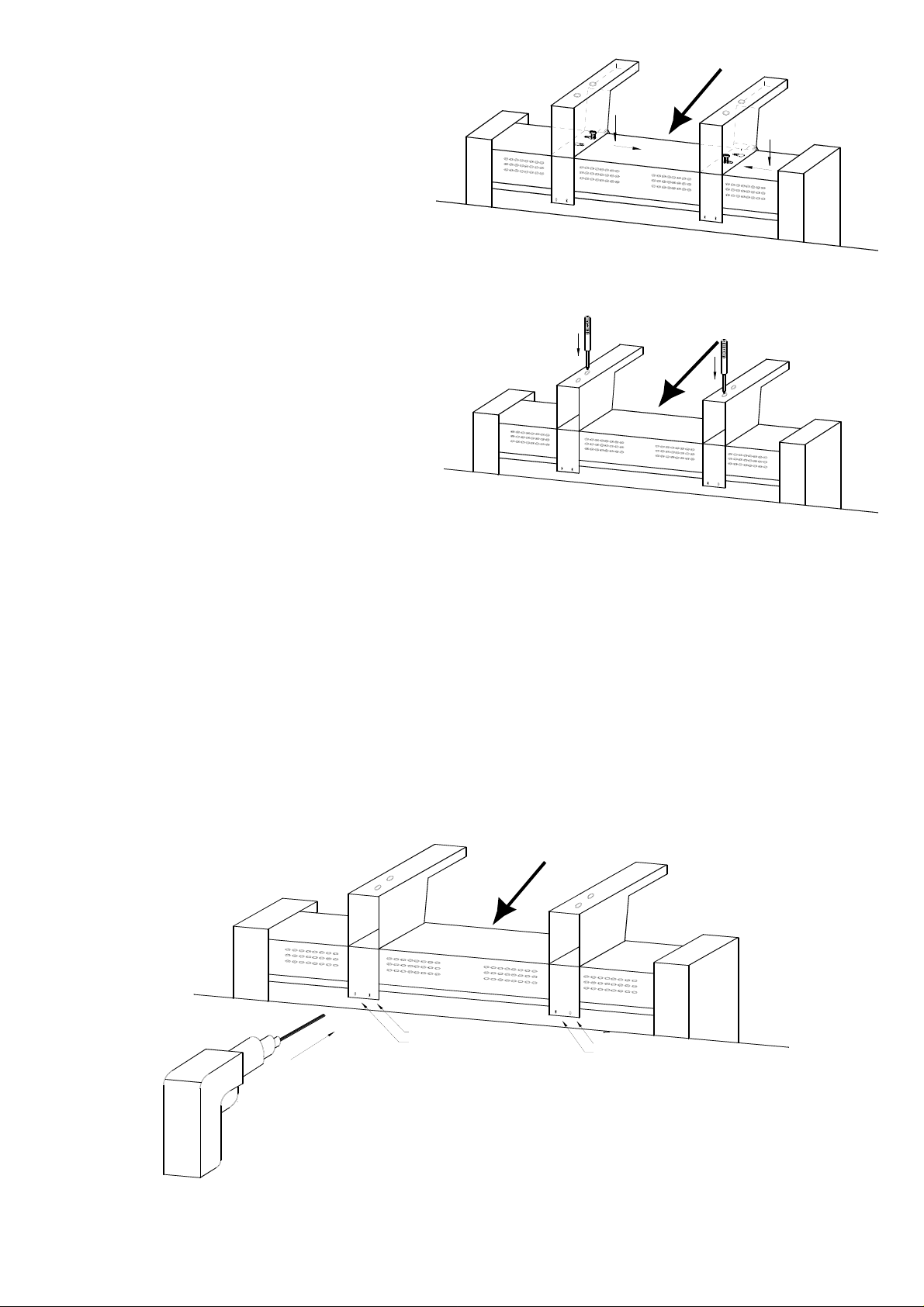
FRONT OF HEATER
6. Slide the foot across until the
screw is located in the smaller
section of the keyhole. See fig 3A.
7. Using a pozi-drive screw driver,
locate the taptite screw through
the hole provided as shown in Fig
3B.
FIG. 3A
8. Note: At this stage the feet must
be parallel and pointing forwards. Tighten both screws se-
curely, ensuring they are located
correctly in the keyholes.
9. Observe holes C,D,E, and F as
shown in fig 4, at the rear fixing
bracket of the floor standing foot.
10. T aking the 2.6mm drill bit supplied
in the fixing kit, drill four holes
through the body of the heater using holes C,D,E and F as a template. Do not allow the drill bit to travel more than 5mm into the heater. Please
ensure the heater is gripped firmly and the feet remain in position.
FIG. 3B
FRONT OF HEATER
11. Secure the back of the feet to the heater by fixing the four No.6 x 3/8" self tapping
screws provided through the holes C,D,E and F.
12. With the feet securely fixed to the heater, rotate the heater onto its feet and then remove the side packing.
13. Cable entry may be effected from either the right or the left side of the unit, but the cable
should be routed around the back of the foot and then fed through the appropriate
retaining clips.
FRONT OF HEATER
FIG. 4
D
C
F
E
83816 Issue 1 : 01.98
 Loading...