

Page 1
D
Montage- und Gebrauchsanweisung
Händetrockner HD 501 AK, HD 601 AM hd501-601_ba 05/08/B
Lesen Sie bitte die Montage- und Gebrauchsanweisung aufmerksam durch.
Bewahren Sie diese Montage- und Gebrauchsanweisung auf.
Geben Sie Ihr Gerät nie ohne Montage- und Gebrauchsanweisung an andere Personen weiter.
Beschreibung Händetrockner
Der Händetrockner dient ausschließlich zum Trocknen der Hände. Die Hände werden im
Warmluftstrom, der am Luftgitter austritt, getrocknet. Durch Reiben der Hände wird das
Händetrocknen beschleunigt
Der Händetrockner ist mit einem Näherungsschalter ausgestattet. Dieser schaltet das Gerät
automatisch ein, wenn die Hände vor das Luftaustrittsgitter gehalten werden. Werden die Hände
aus dem Bereich des Luftstroms genommen, schaltet der Näherungsschalter das Gerät nach
einer Nachlaufzeit von ca. 2 Sekunden automatisch ab.
Die Montage des Händetrockners darf nur in einem geschlossenen Raum erfolgen.
Der Händetrockner wird an einer senkrechten Wand mit der Luftaustrittsöffnung nach unten
montiert. Das Gerät ist nur für Festanschluss ausgelegt.
Die Montage und der elektrische Anschluss des Gerätes sind nur durch den Fachmann
zugelassen!
Die Schutzmaßnahmen sind unter Berücksichtigung der einschlägigen nationalen Bestimmungen
auszuführen! Es ist eine allpolige Trennvorrichtung mit mindestens 3 mm Kontaktöffnungsweite
in die elektrische Installation einzubauen!
Technische Daten
Typ HD 501 AK HD 601 AM
Betriebsspannung 220-240 V~ 50/60 Hz 220-240 V~ 50/60 Hz
Nennleistung 1640 Watt 1640 Watt
Schutzart IP 21 IP 21
Schutzklasse II, Schutzisoliert II, Schutzisoliert
Anschlussart Festanschluss Festanschluss
Montageart Wandmontage Wandmontage
Bedienung Näherungsschalter Näherungsschalter
Nachlaufzeit 2 Sekunden 2 Sekunden
Luftdurchsatz 280 m3/h 280 m3/h
Geräuschpegel 60 dB (2 m) 60 dB (2 m)
Maße B x H x T 253 x 302 x 149 mm 255 x 302 x 140 mm
Gewicht 3,0 kg 4,4 kg
Technische Änderungen vorbehalten
Lieferumfang Händetrockner
Der Händetrockner wird komplett mit Bohrschablone, Spezialschlüssel und Befestigungsmaterial
geliefert.
1
Page 2
Montage
Empfohlene Anbauhöhe Fußboden bis Unterkante des Händetrockners:
Erwachsene 120 cm; Rollstuhlfahrer, Kinder 100 cm.
Mindestabstand 40 cm in Ausblasrichtung zu Wandkonsolen, Waschbecken etc. einhalten!
Im Bereich des Sensorfensters reflektierende Oberflächen vermeiden!
Die Schutzbereiche gemäß VDE 0100 Teil 701sind bei der Wahl des Montageortes zu beachten!
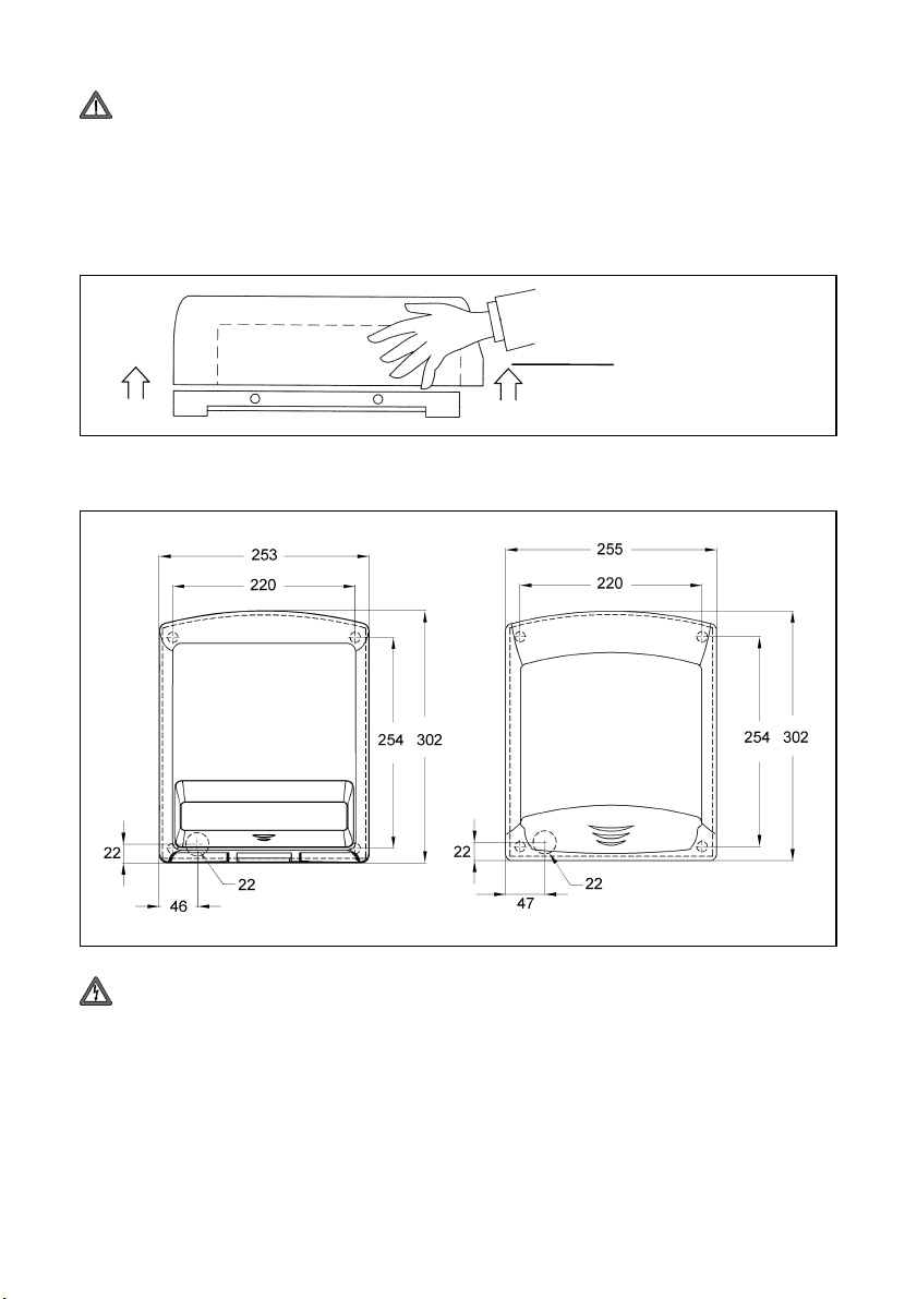
Die Gehäusedeckel-Schrauben sind lose beigelegt (im Beipack). Gehäusedeckel senkrecht nach
oben abnehmen. Darauf achten, dass die Sensoreinrichtung des Näherungsschalters nicht
beschädigt wird.
Sensoreinrichtung
Im Verpackungskarton liegt eine Bohrschablone mit den Abmessungen der Grundplatte.
Der Händetrockner ist unter Beachtung nachfolgender Montagemaße an einer senkrechten
Wand mit der Luftaustrittsöffnung nach unten zu befestigen.
HD 501 AK HD 601 AM
Einführung
Maße in mm
Die vier Befestigungsbohrungen 220 mm x 254 mm kennzeichnen (siehe Abbildung oben).
Vor der weiteren Montage entsprechenden Stromkreis vom Netz trennen
(Sicherung ausschalten)!
Beim Dübel setzen auf eventuell im Mauerwerk liegende elektrische Leitungen achten!
Es besteht die Gefahr eines Stromschlages!
Dem Gerät liegen die Schrauben und Dübel zur Wandbefestigung bei. Je nach Wandaufbau
(z.B. Leichtbauwände) muss jedoch spezielles Befestigungsmaterial verwendet werden, dass
vom Fachmann festzulegen ist
Dübellöcher Ø 8 mm bohren und Dübel einsetzen.
Netzanschlussleitung abisolieren und durch die Öffnung der Geräterückwand führen.
Geräterückwand an der Befestigungswand festschrauben.
Netzanschlussleitung
2
Einführung
Netzanschlussleitung
Page 3
Elektrischer Anschluss
Klarsichtabdeckung anheben und elektrische Zuleitung an die Klemmleiste anschließen.
Klemmenbeschriftung (L,N) beachten. Klarsichtabdeckung wieder ordnungsgemäß anbringen.
Das Gerät ist schutzisoliert, kein Schutzleiter erforderlich.
Endmontage
Gehäusedeckel aufsetzen. An beiden Geräteseiten je zwei Gehäuseschrauben einsetzen und
festdrehen.
Bedienung
Das Luftaustrittsgitter wird bei Betrieb heiß. Nicht berühren oder abdecken!
Der Händetrockner ist mit einem Näherungsschalter ausgestattet, der, wenn die Hände zum
Trocknen vor das Luftaustrittsgitter gehalten werden, automatisch einschaltet und solange in
Betrieb bleibt, bis die Hände aus dem warmen Luftstrom genommen werden. Die Nachlaufzeit
beträgt ca. 2 Sekunden.
Durch Umstecken eines Steckverbinders (Jumper) durch den Fachmann an der Elektronikplatine
kann die Ansprechempfindlichkeit des Näherungsschalters geändert werden
Siehe dazu umseitigen Abschnitt „Schaltbild“.
Reinigung
Gerät nur im abgekühlten Zustand reinigen!
Die Geräteoberfläche und das Sensorfenster (an der Geräteunterseite) mit einem feuchten
Lappen abwischen und abtrocknen. Keine scharfen oder scheuernden Reinigungsmittel
verwenden. Das Gerät darf nicht mit Wasser abgespritzt werden.
Staubansammlungen im Gerät können an der Luftausblasöffnung abgesaugt werden.
Das Öffnen des Händetrockners darf nur von einem Fachmann vorgenommen werden!
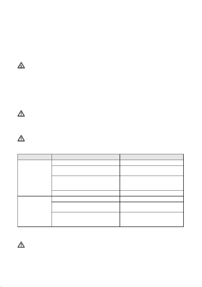
Hilfe bei Störungen
Störung Mögliche Ursache Abhilfe
Haushaltssicherung hat ausgelöst. Sicherung überprüfen.
Kein Warmluft-
strom spürbar
Sensorfenster stark verschmutzt Sensorfenster reinigen
Zu geringer Abstand zu Ablage. Abstand zu Ablage min 400 mm.
Gerät schaltet
unbeabsichtigt ein
Ist die Störung nicht mit den oben aufgeführten Abhilfen zu beseitigen, schalten Sie die Sicherung aus
und ziehen Sie einen Fachmann hinzu, oder wenden Sie sich an die umseitig genannte Service-Stelle.
Die Reparatur des Händetrockners darf nur von einem Fachmann vorgenommen werden!
Überhitzungsschutz hat ausgelöst. Gerät ausreichend abkühlen lassen.
Sensorfenster des Näherungsschalters
mutwillig abgedeckt (z.B. durch
Kaugummi, Klebestreifen etc.).
Reflektierende Gegenstände im
Bereich des Sensors
Ansprechempfindlichkeit des
Näherungsschalters zu hoch.
Fremdkörper vom Sensorfenster
entfernen, Sensorfenster des
Näherungsschalters reinigen.
Gegenstände entfernen
Nur durch Fachmann:
Ansprechempfindlichkeit verringern
(Siehe Abschnitt „Schaltbild“).
3
Page 4

Schaltbild
L Phase R Heizelement
M Motor S Näherungsschalter
N Nullleiter STR 1 Sicherheitsregler Heizelement
P1, P2 Netz Elektronik STR 2 Sicherheitsregler Motor
Service
Nachstehend die bundeseinheitlichen Servicerufnummern für die Robert Bosch Hausgeräte
Kundendienststellen.
Robert Bosch Hausgeräte GmbH Deutschland
Auftragsannahme Telefon: 01801-22 33 55
Telefax: 01801-33 53 07
Ersatzteilbestellungen Telefon: 01801-33 53 04
Telefax: 01801-33 53 08
E-Mail: spareparts@bshg.com
Robert Bosch Hausgeräte GmbH Österreich
Auftragsannahme Telefon: 0810-24 02 60
Telefax: (01) 6057-55 12 12
Ersatzteilbestellungen Telefon: 0810-24 02 61
Telefax: (01) 6057-55 12 12
E-Mail: hausgeraete.ad@bshg.com
Für die Auftragsbearbeitung werden die Erzeugnisnummer E-Nr. und das Fertigungsdatum FD
des Gerätes benötigt. Diese Angaben befinden sich auf dem Typschild, in dem stark umrandeten
Feld.
Garantie
Für dieses Produkt übernehmen wir 2 Jahre Garantie gemäß unseren Garantiebedingungen
Entsorgungshinweis
Das Gerät darf nicht im allgemeinen Hausmüll entsorgt werden.
Glen Dimplex Deutschland GmbH Telefon +49 (0) 9221 709-564
Am Goldenen Feld 18 Telefax +49 (0) 9221 709-589
D-95326 Kulmbach E-Mail: kundendienst.hauswaerme@dimplex.de
Technische Änderungen vorbehalten www.dimplex.de
4
Page 5

Installation and Operating Instructions
Hand Dryer HD 501 AK, HD 601 AM hd501-601_ba 06/08/C
These installation and operating instructions should be read carefully and retained for future
reference.
Ensure that these installation and operating instructions are passed on to any new owner.
Description of Hand Dryer
The sole purpose of the hand dryer is to dry hands. The hands are dried in a stream of warm air
that flows out of the air outlet grille. The hands can be rubbed together to accelerate drying.
The hand dryer is operated by a proximity switch which starts the unit automatically when hands
are placed under the air outlet grille. When the hands are removed from the airflow, the proximity
switch automatically stops the dryer after a run-on delay of approximately 2 seconds.
The hand dryer is designed to be mounted indoors only.
It must be mounted on a vertical wall with the air outlet opening pointing downwards. The
appliance should only be connected to the fixed wiring of the premises.
The installation and electrical connection of the hand dryer may only be performed by a
competent electrician!
All safety measures taken must conform to the applicable national regulations effective in the
relevant country! The electrical supply circuit to the dryer must incorporate an isolating switch
with at least 3mm contact clearance on each pole!
Technical Specifications
Type HD 501 AK HD 601 AM
Operating voltage 220-240 V~ 50/60 Hz 220-240 V~ 50/60 Hz
Rated power 1640 W 1640 W
Enclosure protection level IP 21 IP 21
Class of protection II, double insulated II, double insulated
Type of connection Fixed connection Fixed connection
Type of mounting Wall mounting Wall mounting
Operation Proximity switch Proximity switch
Time delay 2 seconds 2 seconds
Airflow rate 280 m3/h 280 m3/h
Noise level 60 dB (2 m) 60 dB (2 m)
Dimensions W x H x D 253 x 302 x 149 mm 255 x 302 x 140 mm
Weight 3.0 kg 4.4 kg
Subject to change without notice
Materials supplied with hand dryer
The hand dryer comes complete with a drilling template, special spanner and mounting
hardware.
5
Page 6

Installation
Recommended mounting height from the floor level to the bottom of the hand dryer:
Adults: 120 cm; wheelchair users, children 100 cm.
There must be a minimum clearance of 40 cm, in the direction of air discharge, from wall
shelves, wash-basins, etc!
Avoid reflecting surfaces within the detection range of the sensor lens!
When choosing the installation location, make sure that the safety distances in accordance with
the relevant regulations are complied with!
The casing screws are supplied loose (in a parts bag). Remove casing cover by lifting it straight
upward. Be careful not to damage the sensor unit of the proximity switch.
Sensor unit
The packing box contains a drilling template with the dimensions of the mounting base.
Mount the hand dryer on a vertical wall with the air outlet opening pointing downwards, bearing in
mind the mounting dimensions detailed below.
HD 501 AK HD 601 AM
Cable entry
Dimensions in mm
Mark the location of the four mounting holes 220 mm x 254 mm (see illustration above).
Disconnect the relevant electrical circuit (remove fuse) before continuing with the mounting
work!
When inserting the rawlplugs, be careful of existing electrical cables in the wall!
Risk of electric shock!
However, special mounting materials may need to be used according to the construction of the
wall (e.g. lightweight partition walls). Seek specialist advice.
Drill Ø 8 mm holes for the rawlplugs and insert the plugs.
Strip the power supply cable and feed it through the opening in the back panel of the device.
Secure the back panel of the unit to the wall using the screws supplied.
6
Cable entry
Page 7

Electrical Connection
Lift transparent cover and connect electrical supply wire to the terminal strip. Pay attention to
terminal markings (L,N). Replace transparent cover.
The appliance is double insulated, no protective conductor is required.
Final Assembly
Replace casing cover. On either side of the appliance casing insert two screws each and tighten.
Operation
When in use, the air outlet grille gets hot. Do not touch or cover!
The hand dryer has a proximity switch which switches the dryer on automatically when hands are
placed under the air outlet grille and switches off when the hands are removed from the hot
airflow. There is a run-on delay of approximately 2 seconds.
The sensitivity of the proximity switch can be adjusted by changing the jumper position on the
electronic circuit board. This must be carried out by a competent electrician.
Please refer to the "Circuit Diagram" section overleaf for details.
Cleaning
Allow appliance to cool before carrying out any cleaning work!
Wipe the outside of the unit and the sensor lens (at the bottom of the unit) with a damp cloth and
dry. No not use any caustic or abrasive cleaning agents. The appliance should not be subjected
to water spray.
Hold a vacuum cleaner against the air outlet opening to remove any dust that may have
accumulated inside the unit.
The hand dryer casing may only be opened by a competent electrician!
Troubleshooting
Problem Possible cause Remedy
Household fuse tripped. Check fuse
No hot
airflow
Sensor lens excessively dirty Clean sensor lens
Insufficient distance from shelf.
Device switches
on accidentally
If the problem cannot be remedied using the methods described above, remove the fuse and consult a
competent electrician, or contact the After Sales Service detailed overleaf.
Overheat protection tripped. Allow unit to cool sufficiently.
Sensor lens of proximity switch has
been deliberately covered (e.g. by
chewing gum, adhesive tape, etc.).
Objects with reflecting surface within
range of sensor.
Sensitivity of proximity switch set too
high.
Remove foreign matter from sensor
lens, clean sensor lens of proximity
switch.
Distance from shelf must be min.
400 mm.
Remove objects.
To be carried out by a competent
electrician: Reduce sensitivity (see
section "Circuit Diagram").
Repairs to the hand dryer should only be carried out by a competent electrician!
7
Page 8

Circuit Diagram
L Phase R Heating element
M Motor S Proximity switch
N Neutral conductor STR 1 Safety cut-out, heating element
P1, P2 Power supply, electronic items STR 2 Safety cut-out, motor
Guarantee
This product is guaranteed for two years in accordance with our guarantee terms.
Disposal
The appliance must not be disposed of with household waste.
Glen Dimplex Deutschland GmbH Telefon +49 (0) 9221 709-564
Am Goldenen Feld 18 Telefax +49 (0) 9221 709-589
D-95326 Kulmbach E-Mail: kundendienst.hauswaerme@dimplex.de
Technical specifications subject to change www.dimplex.de
8
 Loading...