

Page 1

WATER HEATER
Instantaneous Electric
Over-Sink Handwash
Installation Instructions
Handyman
Glen Dimplex UK Limited, Millbrook House, Grange Drive, Hedge End, Southampton SO30 2DF.
Tel 0870 077 7117 Fax 0870 727 0109 Email customer.services@glendimplex.com
Customer Services Tel 0870 240 9402
Dimp-13460-HandyInstruction-rob 4/22/04 5:18 PM Page 1
Page 2
Contents
1 x Handwash Unit
1 x Swivel Arm and sprayhead
1 x Screw Pack
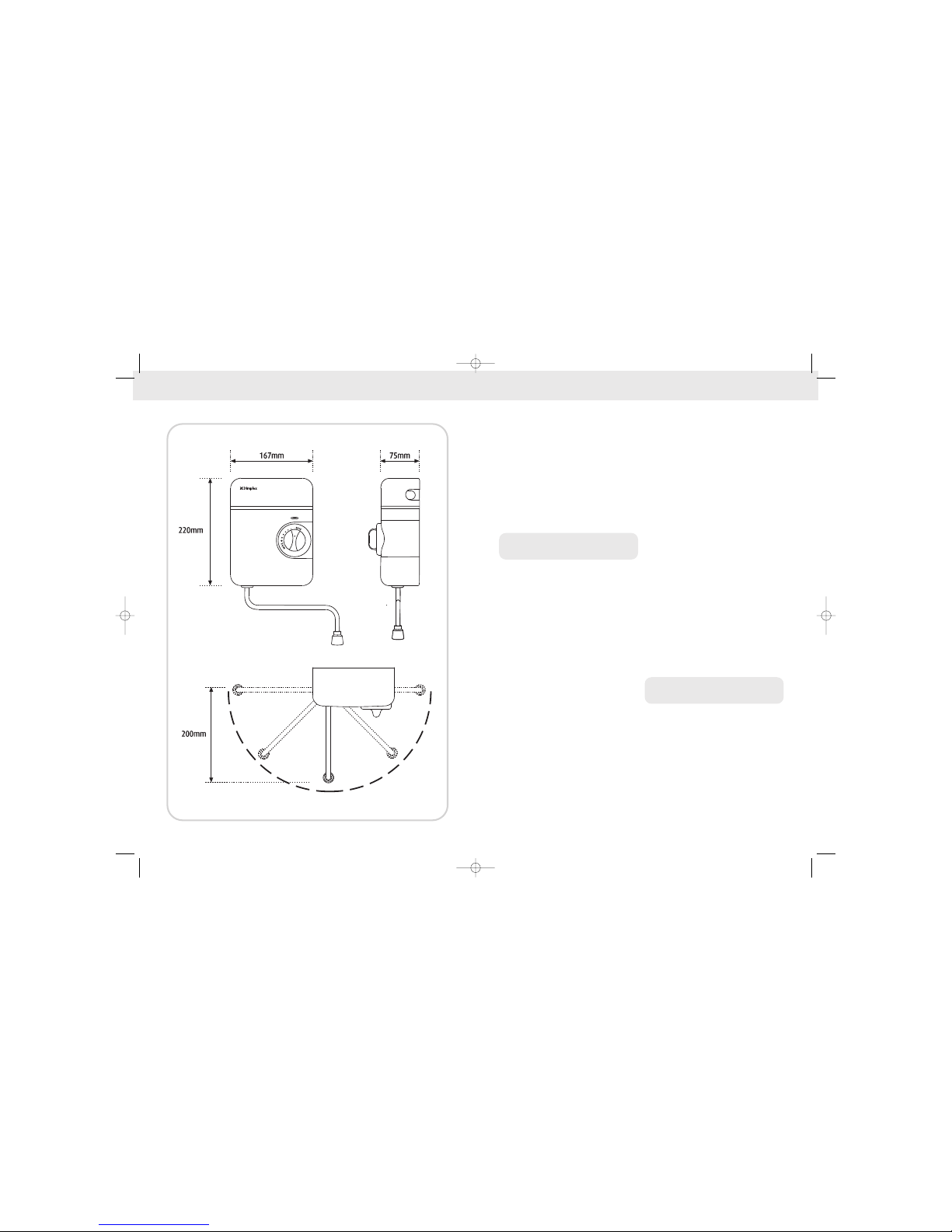
Specification
Power Rating: 2.7kW at 230V/3kW at 240V
Vented Open Outlet System
High Temperature cut-out: 55OC+/–3OC
Electricity Supply~230-240V/50Hz
SECTION 1
Important
1) Installation must be carried out by a
suitably qualified person and conform with
IEE Regulations and National Water council
bylaws.
2) This Handwash unit is designed to be
connected to a 15mm cold water mains
supply.
Do not connect to a tank supply.
3) All plumbing connections must be
completed before making the electrical
connections.
4) The minimum recommended running
water pressure to which the Handwash
may be connected is 15lb/sq in (1 Bar)
running pressure at 8 litres per minute.
The maximum static pressure
recommended is 150lb/sq in (10 bar).
5) The Handwash unit must not be fitted
where it may be exposed to frost, for
example in an outdoor area. The
handwash must not be used if suspected
of being frozen. Frost damage is not
covered by the guarantee.
6) Plumbers jointing compound should not be
used. The use of compound invalidates the
guarantee.
7) The outlet of your handwash acts as a vent
and must NOT be connected to any form
of tap or fitting other than that supplied
with the unit.
8) The sprayhead must be cleaned regularly
to remove the scale and debris. If the
water becomes hot and you are unable to
obtain cooler water, check the spray head
for blockage.
9) The handyman heats water as it passes
through the unit. Water temperature may
therefore vary accordingly to changes in
water flow and temperature, which may
be affected by other water apparatus
operated in the building and seasonal
variations in incoming water temperature.
10)
Not suitable for drinking water.
SECTION 2
Installation
Plan the Installation carefully, before starting
any part of the installation.
Use only the rising main, do not connect the
handwash unit to the down service from a
cold water storage tank.
The water supply pipe may enter the unit
either from the bottom or the rear of the unit.
UNPACKING AND IMPORTANT NOTICES / INSTALLATION
Handyman
Dimp-13460-HandyInstruction-rob 4/22/04 5:18 PM Page 3
Page 3

INSTALLATION INSTALLATION
SECTION 3
Plumbing
Fit an isolation valve in the cold mains supply
preceding the installation point of the
handyman unit to allow the unit to be serviced.
Turn the temperature Control so that it is set to
‘MIN’.
Remove the front cover by unscrewing the
screw at the bottom of the unit and lifting the
cover, complete with control knob, off the
handwash unit.
Place the handwash unit on the wall, ensuring
it is level, and mark the location of the fixing
screws through the backplate.
The following procedure assumes installation
onto a sound masonry surface, if installing
onto other surfaces the procedure and fixings
may need to be modified.
Carefully drill the holes using a 5.5mm
masonry drill-bit and insert the rawl plugs into
the holes.
Place the unit on the wall and secure it using
the screws provided.
Run the water supply to the unit using 15mm
copper or stainless pipe and flush the
pipework for several seconds to remove any
flux and debris within the pipe, before
connecting to the unit.
Connect the mains water supply to the blue
water inlet on the handwash unit using the
compression nut and olive provided. Take
care not to use excessive force when
tightening the compression nut.
Fit the swivel arm to the end outlet of the
handwash unit.
With the unit fully plumbed in turn on the
mains water supply and check the system for
leaks.
SECTION 4
Electricity Supply
Warning this appliance must be earthed!
The unit is suitable for connection to
~230-240V/50Hz supply only
The wiring must conform to with I.E.E. wiring
regulations. If in doubt seek professional advice.
The unit may be supplied from a ring circuit
via a fused spur with a double pole linked
isolating switch fitted with a 13A fuse. The
supply cable should be 3 core and of 1.5
–2.5mm diameter.
The cable should be routed to the handwash
unit so that it enters either via the cable entry
point at the top right hand side of the unit or
through the break-out hole at the rear of the
unit.
The cable grommet should be inserted at the
entry point and the wire routed into the unit.
Connect the Live wire to the terminal
marked L.
Connect the Neutral wire to the terminal
marked N.
Connect the Earth wire to the terminal
marked E.
Ensure that the terminal screws are fully tightened
and good electrical continuity is achieved.
Secure the cable to the unit using the cable
clamp.
Do no switch on the electricity supply to
the unit!
SECTION 5
Final Assembly
Ensuring the temperature control knob is set to
‘MIN’, place the cover carefully onto the
handwash unit and secure using the fixing
screws.
SECTION 6
Commissioning
Turn the temperature control knob
anti-clockwise to its ‘MAX’ setting and allow
water to flow through the unit until a
continuous stream of water, free of air bubbles
is achieved.
Switch on the electrical supply at the isolating
switch. The Power indicator should light.
After a few seconds check that the water from
the unit is beginning to get warm. Adjust the
temperature control clockwise and check that
after a few seconds the water becomes
hotter.
Turn off the unit by turning the temperature
control knob fully clockwise. Switch off the
electricity supply at the isolation switch
SECTION 7
Operation
Switch on
1) Turn on the electricity supply at the isolating
switch. The power indicator should light.
2) Turn the temperature control knob anti-
clockwise to its ‘MAX’ position – indicating
maximum water flow.
3) After a few seconds the water should run
warm, ready for use.
4) If the temperature is required to be increased
turn the knob slowly clockwise, wait a few
seconds until the water temperature
stabilises and adjust again if necessary.
5) To reduce the water temperature turn the
knob anti-clockwise.
Do not under any circumstances restrict or
cover the sprayhead or try to prevent water
exiting the handwash unit as this will cause
the safety cut-out to operate.
Turn off
1) To turn the unit off, turn the temperature
knob fully clockwise until the water stops
flowing. Note: some water may continue
to drip from the unit for a few minutes
as excess water drains from the unit.
2) Switch off the electricity supply at the
isolating switch.
Note: variation in water temperature is
achieved by varying the flow of water through
the unit, hence for higher temperatures you
will notice a reduction in the flow of water
from the handwash unit.
Dimp-13460-HandyInstruction-rob 4/22/04 5:18 PM Page 5
Page 4

GUARANTEE
Glen Dimplex UK Limited guarantee this
product for a period of one year, from
date of purchase, against mechanical
defects arising from faulty materials
or from poor manufacturing
workmanship, providing the product
has been installed by a competent
person in accordance with the fitting
instructions.
Glen Dimplex UK Limited undertake
to repair or replace, at their discretion,
without charge, provided the product
has been properly maintained and
operated in accordance with the
operating instructions. Any component
found to be defective during this
period, as the result of misuse or
damage, or the effects of scaling, will
not be covered by this guarantee.
This product must not be modified,
repaired or taken apart except by a
person authorised by Glen Dimplex UK
Limited.
This guarantee is only valid within the
United Kingdom.
This guarantee does not affect your
statutory rights.
COOLER
WARMER
WARMER
Handyman
INSTALLATION / OPERATION
SECTION 8
Maintenance
The sprayhead should be cleaned periodically
to remove limescale and any other particles
trapped in the swivel arm. This may be done
by unscrewing the sprayhead and scrubbing
with a stiff-bristled brush.
If necessary immerse the sprayhead in a
proprietary limescale remover for several hours
and scrub away loose deposits. Rinse the
sprayhead thoroughly before attaching to the
swivel arm.
Service Policy
Should you need to contact the Dimplex
Customer Service Centre regarding any
fault with this product please have the Model
Number; Serial Number and Date
of Purchase of the Product readily available.
Dimp-13460-HandyInstruction-rob 4/22/04 5:18 PM Page 7
 Loading...