

Dimplex DWF1203, DWF-1326 Service Manual
Service Manual
Model
DWF1203
Part Number
6908490100
IMPORTANT SAFETY INFORMATION: Always read this manual rst before attempting to service this replace. For your
safety, always comply with all warnings and safety instructions contained in this manual to prevent personal injury or property damage.
Dimplex North America Limited
1367 Industrial Road
1-888-346-7539
In keeping with our policy of continuous product development, we reserve the right to make changes without notice.
© 2012 Dimplex North America Limited
Cambridge ON Canada N1R 7G8
www.dimplex.com
REV PCN DATE
00 - 7-AUG-12
7400580000R00

TABLE OF CONTENTS
OPERATION .........................................................3
MAINTENANCE . . . . . . . . . . . . . . . . . . . . . . . . . . . . . . . . . . . . . . . . . . . . . . . . . . . . . . 4
EXPLODED PARTS DIAGRAM . . . . . . . . . . . . . . . . . . . . . . . . . . . . . . . . . . . . . . . . . . 5
REPLACEMENT PARTS LIST ...........................................5
WIRING DIAGRAM ....................................................6
SWITCH REPLACEMENT . . . . . . . . . . . . . . . . . . . . . . . . . . . . . . . . . . . . . . . . . . . . . . 7
PARTIALLY REFLECTIVE GLASS REPLACEMENT . . . . . . . . . . . . . . . . . . . . . . . . . 7
FLAME PANEL REPLACEMENT .........................................8
POWER CORD REPLACEMENT .........................................8
HEATER ASSEMBLY REPLACEMENT ....................................9
CIRCUIT BOARD REPLACEMENT . . . . . . . . . . . . . . . . . . . . . . . . . . . . . . . . . . . . . 10
Remote Control Receiver or LED Driver Board ..............................................10
FLICKER ROD REPLACEMENT . . . . . . . . . . . . . . . . . . . . . . . . . . . . . . . . . . . . . . . . 10
FLICKER MOTOR REPLACEMENT . . . . . . . . . . . . . . . . . . . . . . . . . . . . . . . . . . . . . 11
LED LIGHT STRIP REPLACEMENT . . . . . . . . . . . . . . . . . . . . . . . . . . . . . . . . . . . . . 12
TROUBLESHOOTING GUIDE . . . . . . . . . . . . . . . . . . . . . . . . . . . . . . . . . . . . . . . . . . 14
Always use a qualied technician or service agency to repair this replace.
!
NOTE: Procedures and techniques that are considered important enough to emphasize.
CAUTION: Procedures and techniques which, if not carefully followed, will result in damage to the equipment.
WARNING: Procedures and techniques which, if not carefully followed, will expose the user to the risk of re, serious
injury, or death.
2 www.dimplex.com
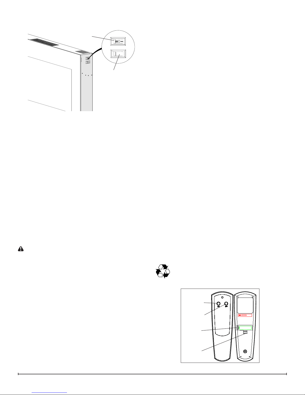
OPERATION
Figure 1
A
B
The manual controls for the electric replace are located on
the right side of the unit (Figure 1).
A. 3-Position Switch
The switch has two (2) On positions marked with “ I ” and “
II ”. The “ I ” position is for manual operation. In this position
the built-in remote control is bypassed.
The “ II ” position is for operating the unit with the provided
remote control. When in “ II ” position the unit is operated
with the ON and OFF buttons of the remote control.
When the switch is in the center (“ O ”) position the unit is
off.
B. Heat On/Off Switch
The Heat On/Off Switch supplies power to the heater fan
and the heater element.
Resetting the Temperature Cutoff Switch
Should the heater overheat, an automatic cut out will turn
the replace off and it will not come back on without being
reset. It can be reset by switching the 3-Position Switch to
Off and waiting ve (5) minutes before switching the unit
back on.
CAUTION: If you need to continuously reset the heater,
disconnect power and call Dimplex customer service at
1-888-DIMPLEX (1-888-346-7539).
Remote Control
The replace is supplied with a radio frequency remote
control. This remote control has a range of approximately
50 feet (15.25 m), it does not have to be pointed at the
replace and can pass through most obstacles (including
walls). It is supplied with one of hundreds of independent
frequencies to prevent interference with other units.
!
NOTE: Ensure that the replace’s 3-Position Switch is
set to the remote control setting (“ II ” position).
To operate, push the ON button to turn replace on, push
the OFF button to turn the replace off.
!
NOTE: Before attempting any operation with the remote
control, pull the plastic insulator strip out from between
the remote casing and battery cover (Figure 2).
Remote Control Initialization/Reprogramming
In the event that your remote control ceases to operate
your replace, follow these steps to re-initialize the remote
control and the remote control receiver in the replace:
Place the 3-Position Switch (Figure 1A) in the Off (“1. O”)
position.
Wait a minimum of ve (5) seconds and then place the 2.
3-Position Switch in the Remote Control (“ II ”) position.
Within 10 seconds of changing the switch position, 3.
press the ON button located on the remote control
(Figure 2).
This will synchronize the remote control and the remote
control receiver.
!
NOTE: You will have only 10 seconds to perform this
last step. Failure to do so will result in these steps needing
to be followed again.
Battery Replacement
To replace the battery:
Slide battery cover open on the remote control (Figure 1.
2).
Install one (1) 12-Volt (A23) battery in the battery 2.
holder.
Close the battery cover3.
Battery must be recycled or disposed of properly.
Check with your Local Authority or Retailer for
recycling advice in your area.
Figure 2
On
Button
Off Button
Plastic
Strip
Battery
Cover
3

MAINTENANCE
WARNING: Disconnect power before attempting any
maintenance or cleaning to reduce the risk of re,
electric shock or damage to persons.
Partially Reective Glass Cleaning
The Partially Reective Glass is cleaned in the factory
during the assembly operation. During shipment,
installation, handling, etc., the Partially Reective Glass
may collect dust particles; these can be removed by
dusting lightly with a clean dry cloth.
To remove ngerprints or other marks, the Partially
Reective Glass can be cleaned with a damp cloth. The
Partially Reective Glass should be completely dried with a
lint free cloth to prevent water spots. To prevent scratching,
do not use abrasive cleaners.
Fireplace Surface Cleaning
Use only a damp cloth to clean painted surfaces of the
replace. Do not use abrasive cleaners.
Servicing
Except for installation and cleaning described in this
manual, an authorized service representative should
perform any other servicing.
4 www.dimplex.com
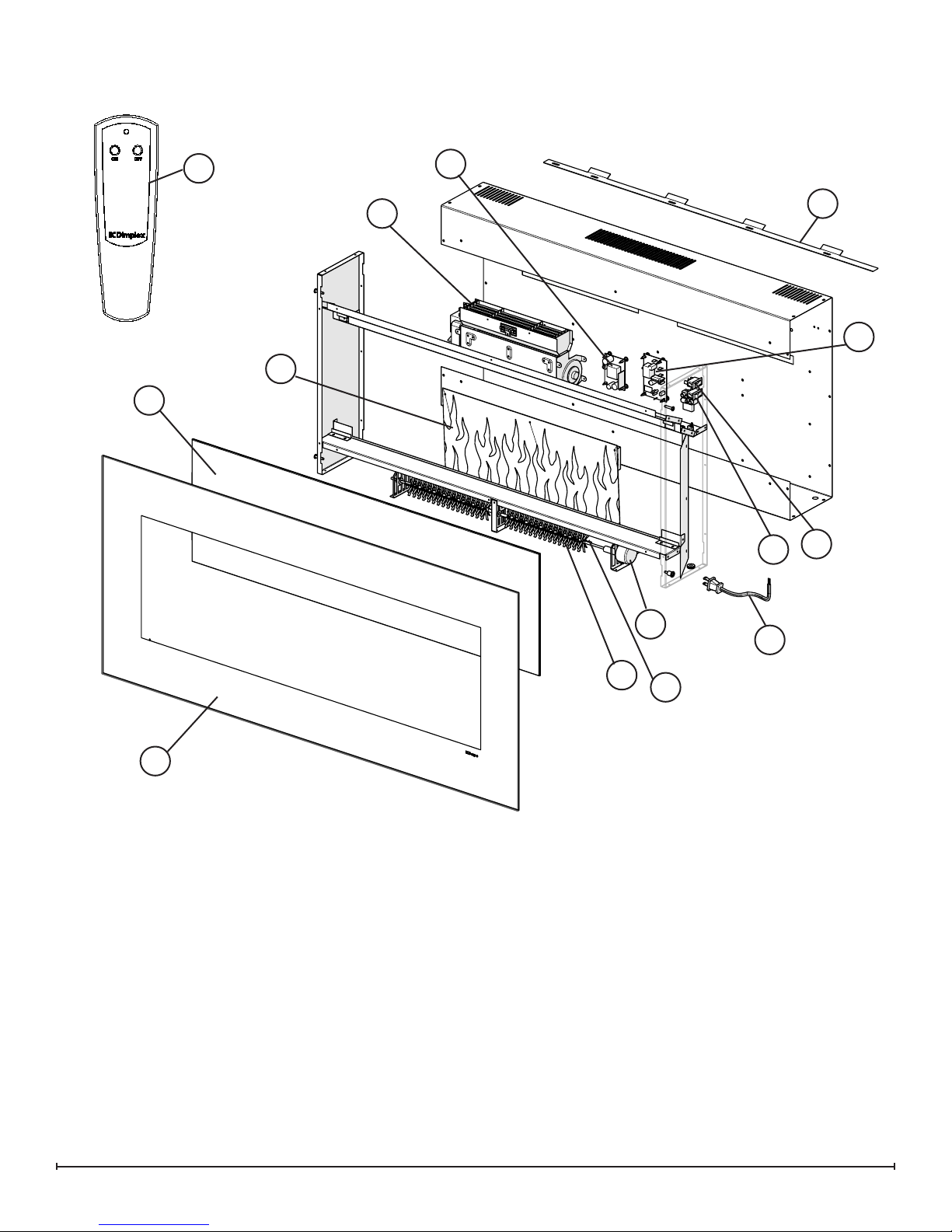
EXPLODED PARTS DIAGRAM
11
1
13
16
10
4
3
9
8
2
REPLACEMENT PARTS LIST
Heater Assembly (with Cutout)1. ............2200490800RP
Front Glass2. . . . . . . . . . . . . . . . . . . . . . . . . . . . 5902440100RP
Partially Reective Glass3. . . . . . . . . . . . . . . . . 5902420100RP
Flame Panel4. . . . . . . . . . . . . . . . . . . . . . . . . . . 5902400100RP
Power Cord5. . . . . . . . . . . . . . . . . . . . . . . . . . . 4100010800RP
Flicker Motor6. . . . . . . . . . . . . . . . . . . . . . . . . . . 2000210500RP
Flicker Rod 7. . . . . . . . . . . . . . . . . . . . . . . . . . . 5901070200RP
Heater On/Off Switch8. . . . . . . . . . . . . . . . . . . . 2800070200RP
6
5
7
12
3-Position Switch9. . . . . . . . . . . . . . . . . . . . . . . 2800070700RP
Remote Control Receiver10. ................ 3000380200RP
Remote Control11. . . . . . . . . . . . . . . . . . . . . . . . 3000820100RP
LED Light Assembly12. .................... 3000830100RP
LED Driver Board13. . . . . . . . . . . . . . . . . . . . . . . 3000810100RP
Glass Rocks14. . . . . . . . . . . . . . . . . . . . . . . . . . . 1400070100RP
Mounting Hardware Kit15. . . . . . . . . . . . . . . . . . . 9600350100RP
Mounting Bracket16. . . . . . . . . . . . . . . . . . . . . . . 1017130259RP
5
 Loading...