

Page 1
This equipment has been tested and found to comply with the limits
for a Class B digital device, pursuant to Part 15 of the FCC Rules.
These limits are designed to provide reasonable protection against
harmful interference in a residential installation. This equipment
generates uses and can radiate radio frequency energy and, if
not installed and used in accordance with the instructions, may
cause harmful interference to radio communications. However,
there is no guarantee that interference will not occur in a particular
installation. If this equipment does cause harmful interference to
radio or television reception, which can be determined by turning
the equipment off and on, the user is encouraged to try to correct
the interference by one of the following measures:
Reorient or relocate the receiving antenna.•
Increase the separation between the equipment and receiver.•
Connect the equipment into an outlet on a circuit different •
from that to which the receiver is connected.
Consult the dealer or an experienced radio/TV technician •
for help.
This device complies with Part 15 of the FCC Rules. Operation
is subject to the following two conditions: (1) This device may
not cause harmful interference, and (2) this device must accept
any interference received, including interference that may cause
undesired operation.
FCC CAUTION:Anychangesormodicationsnotexpressly
approved by the party responsible for compliance could void the
user’s authority to operate this equipment.
This device complies with Industry Canada licence-exempt RSS
standard(s). Operation is subject to the following two conditions:
(1) this device may not cause interference, and (2) this device must
accept any interference, including interference that may cause
undesired operation of the device.
Under Industry Canada regulations, this radio transmitter may
only operate using an antenna of a type and maximum (or lesser)
FEATURES
Attractive styling suits all décors•
Includes Celsius or Fahrenheit •
temperature control
Electronic sensing for temperature •
by 0.5°C or F
Economy Setting for temporary •
temperature settings
SPECIFICATIONS
Electrical Rating
Battery controlled (CR2032 - 3V)•
Temperature Setpoint Range
0°C – 30°C and 32°F – 86°F•
Mounting:
Mounted directly into a standard 2x4 inch vertical •
electrical outlet box.
Mounted directly to wall•
Wall Mounted Remote Control
DPCRWS Series
Operation
The Wall Mounted Remote control has been designed to control
a single, or multiple Linear Proportional Convector Heaters. It is
programmed to pick an address that both the Remote Control and
synchronized heaters will use to communicate with each other. The
remote sends an RF signal, 5 seconds after any button has been
pressed, to the Linear Proportional Convector Heater.
When the Wall Mounted Remote Control has been synchronized
with multiple heaters, the signal will be sent to the closest heater
and that heater will then in turn send the signal to the next heater
within a 50’ (15m) radius. As long as the heaters are located
within 50’ (15m) of each other and are synchronized with the
Wall Mounted Remote, the remote control will control as many as
desired.
!
NOTE: When the heaters and the Wall Mounted Remote
Control have been synchronized, it is possible to adjust any of the
individual heater settings based on variations from room to room.
However, if one of the buttons on the Remote Control is pressed
the settings will revert back to the ones on the Remote Control.
A. Set Point Temperature
Pressing the + or - will increase or decrease the desired Set Point
Temperature for the room to be heated by 0.5° (in either °C or °F).
!
NOTE: Pressing the + and - at the same time will toggle
between displaying °C and °F.
B. Economy Setting
The Economy Setting can be used to change the Setpoint
Temperature for a variable period of time. By pressing the V the
EconomySettingwillbeenabled-signiedbytheiconashing.
After the Set Back Temperature has been set, the icon will
show solid on the display after three seconds and the Set Back
Temperature will be enabled.
To return back to the Comfort Setting press the V button and the
icon will disappear and the icon will appear.
C. Set Back Temperature Setting
The Set Back Temperature Setting is used during periods when the
Economy setting feature is active. This temperature adjustment
can be set by pressing the V followed by the + or -.
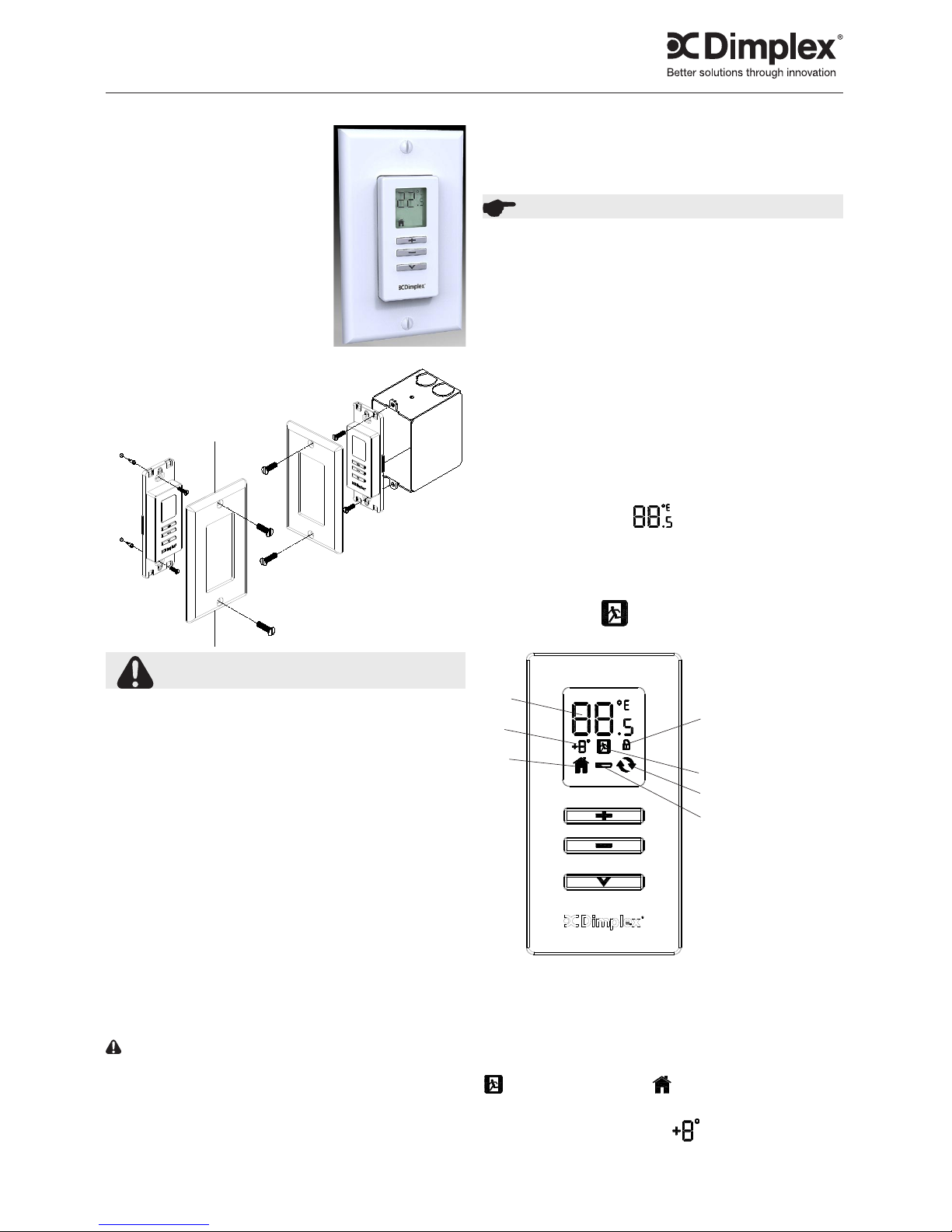
A
C
D
F
B
E
G
A - Set Point Temperature
B - Economy Setting Icon
C - Set Back Temperature
Setting
D - Comfort Setting Icon
E - Synchronized Icon
F - Lock Icon
G - Low Battery Icon
H - Decrease Button
I - Increase Button
J - Menu Button
7211710100R03
ImportAnt InstruCtIons
gain approved for the transmitter by Industry Canada. To reduce
potential radio interference to other users, the antenna type and its
gain should be so chosen that the equivalent isotropically radiated
power (e.i.r.p.) is not more than that necessary for successful
communication.
Page 2
LIMITED WARRANTY: All Dimplex Thermostats and controllers
are warranted against defects in workmanship and materials
for one year from date of sale. This warranty does not apply
to damage from accident, misuse, or alteration, nor where the
connected voltage is more that 5 % above the nameplate voltage,
nor to equipment improperly installed or wired or maintained in
violation of the instruction sheet. This limited warranty applies only
to purchases made in any province of Canada except for Yukon
Territory, Nunavut, or Northwest Territories or in any of the 50
States of the USA (and the District of Columbia) except for Hawaii
and Alaska. This limited warranty applies to the original purchaser
of the product only and is not transferable. No other written or oral
warranty applies. No employee, agent, dealer or other person
is authorized to give any warranties on behalf of Dimplex. The
customer shall be responsible for all costs incurred in the removal
or reinstallation and shipping of the product for repairs. Within the
limitations of this warranty, inoperative units shall be returned to
the nearest Dimplex authorized service center, and we shall repair
or replace, at our option, at no charge to you with return freight
paid by Dimplex. It is agreed that such repair or replacement is
the exclusive remedy available from Dimplex and that DIMPLEX IS
NOT RESPONSIBLE FOR DAMAGES OF ANY KIND, INCLUDING
INCIDENTAL AND CONSEQUENTIAL DAMAGE. Some States
do not allow the exclusion or limitation of consequential damages,
so the above exclusion or limitation may not apply to you. This
warrantygivesyouspeciclegalrightsandyoumayalsohave
other rights which vary from state to state.
Warranty
D. Comfort Setting
The Comfort Setting icon will be displayed when the Wall
Mounted Controller is in normal operation based on the Setpoint
Temperature for the room.
!
NOTE: Either the or icon will always be visible,
dependent on the setting being used.
E. Synchronized Icon
The Wall Mounted Remote Control will control one or multiple
Linear Proportional Convector Heaters within a 50’ (15 m)
radius. In order for the wall setter to have this function the
Linear Proportional Convector and the Wall Setter need to be
Synchronized.
On the Linear Proportional Convector press and hold the 1. V
button for 3 seconds, both the
and icons will begin
toash.
Press the 2. - , + and then V, on the Linear Proportional
Convector.
Within 10 seconds press any button once on the Wall Setter.3.
!
NOTE: There is a 3 second delay between pressing the last
button on the wall setter and the LPC’s receipt of signal.
!
NOTE: To desynchronize a Linear Proportional Convector from
the synchronized Wall Setter, on the Linear Proportional Convector:
Press and hold the 1. V for 3 seconds.
Press the 2. V, + and then -.
Nothing will need to be done to the Wall Setter.
F. Lock Icon
The Wall Mounted Remote Control has a Button Lock feature, to
prevent settings from accidentally being changed.
Press and hold the 1. V for 3 seconds. Both the
and
Iconswillbegintoash.
To Enable:2. Within 5 seconds press +, then -, then +, then -.
The
icon will now be visible.
To Disable: Within 5 seconds press -, then +, then -, then +.
The
icon will no longer be visible.
!
NOTE: The remote control can be locked in either the Comfort
or Economy Setting. Ensure that the desired icons are present
when locking is complete.
Battery Prongs
1367 Industrial Road Cambridge ON Canada N1R 7G8
1-888-346-7539
www.dimplex.com
In keeping with our policy of continuous product improvement, we reserve the right to make changes without notice.
© 2011 Dimplex North America Limited
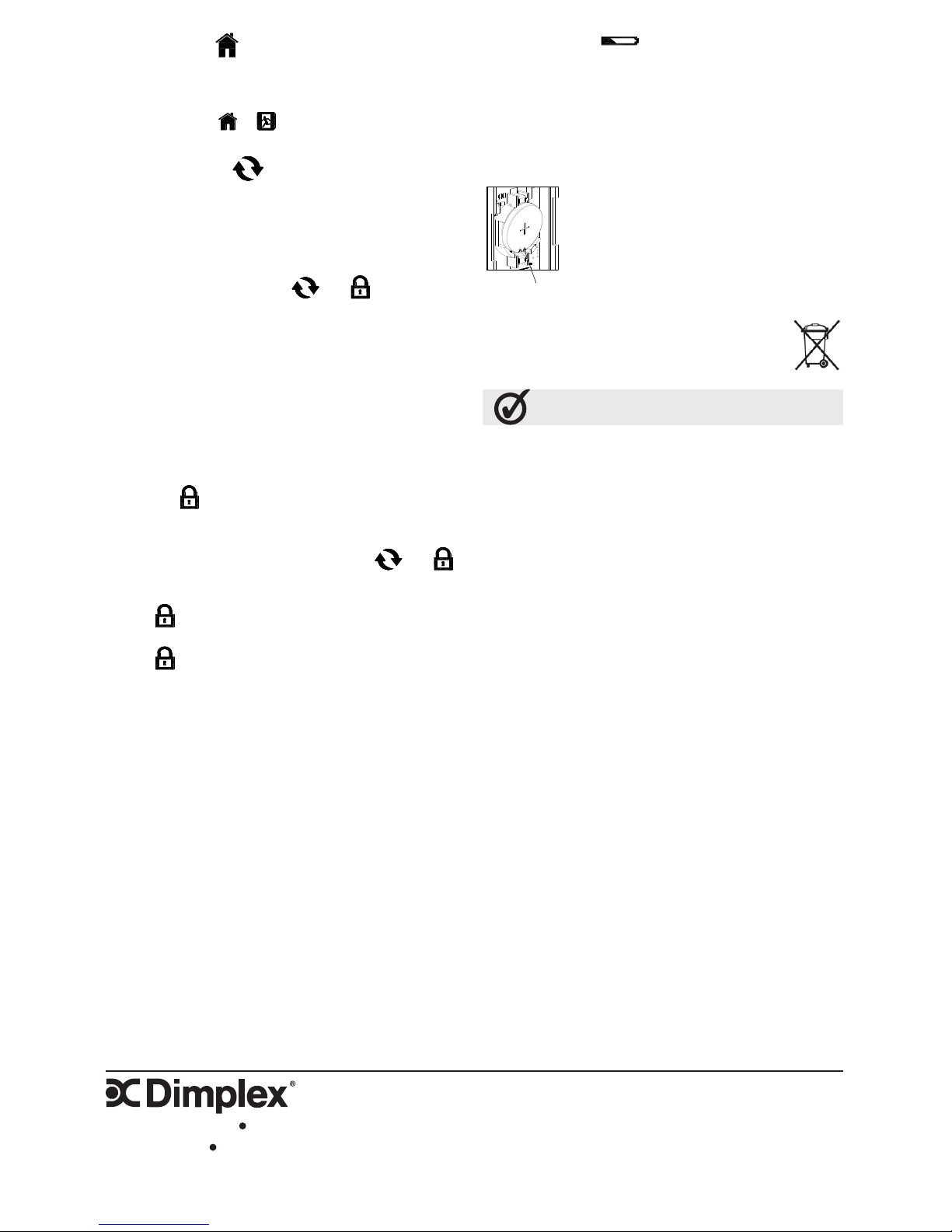
G. Low Battery Icon
The Wall Mounted Remote Control is powered by a CR2032 (3V)
battery. When the battery is nearing the end of its life the Low
Battery Icon will appear on the LCD display.
To change the battery:
Remove the Wall Mounted Remote Control from the 1.
electrical box.
Remove the back plastic cover from the remote control.2.
Replace the battery.3.
!
NOTE: Ensure that battery is installed under
bottom battery prongs.
Reassemble and remount remote control.4.
!
NOTE: Wall Mounted Remote Control will retain
all settings while battery is removed and will revert
to those settings when power is restored.
Recycling Notice
At the end of the electrical products useful life it should
not be disposed of with household waste. Please recycle
where facilities exist. Check with your Local Authority or
retailer for recycling advice in your country.
 Loading...