

Dimplex EWM-COPPER, EWM-SS, DFP20-BW1009 Parts & Service Manual
PARTS & SERVICE MANUAL
EWM-COPPER
EWM-SS
DFP20-BW1009
7400300000R01

TableofContents
OPERATION ......................................................................................................... 3
MAINTENANCE .................................................................................................... 5
EXPLODED VIEW ................................................................................................ 7
REPLACEMENT PARTS ...................................................................................... 8
WIRING DIAGRAM ............................................................................................... 9
TO REPLACE MAIN ON/OFF SWITCH .............................................................. 10
TO REPLACE FLAME MOTOR/FLAME ROD .................................................... 11
TO REPLACE HEATER ON/OFF SWITCH ........................................................ 12
TO REPLACE HEATER ASSEMBLY ................................................................. 13
TO REPLACE HEATER THERMOSTAT CONTROL .......................................... 14
TO REPLACE REMOTE CONTROL RECEIVER ............................................... 15
TO REPLACE THE POWER CORD ................................................................... 16
TROUBLE SHOOTING GUIDE ........................................................................... 17
APPEARANCE ................................................................................................ 17
HEATER ASSEMBLY ..................................................................................... 18
NOISE ............................................................................................................. 20
GENERAL ....................................................................................................... 21
2
OPERATION
A 15 Amp, 120-volt circuit is required. A dedicated circuit is preferred but not
essential in all cases. A dedicated circuit will be required if, after installation, the
circuit breaker trips or fuse blows on a regular basis when the heater is
operating. Additional appliances on the same circuit may exceed the current
rating of the circuit breaker.
WARNING: Ensure the power cord is not installed so that it is pinched or against
a sharp edge and ensure that the power cord is stored or secured to avoid
tripping or snagging to reduce the risk of fire, electric shock or injury to persons.
Construction and electrical outlet wiring must comply with local building codes
and other applicable regulations to reduce the risk of fire, electric shock and
injury to persons.
Do not attempt to wire your own new outlets or circuits. To reduce the risk of fire,
electric shock or injury to persons, always use a licensed electrician.
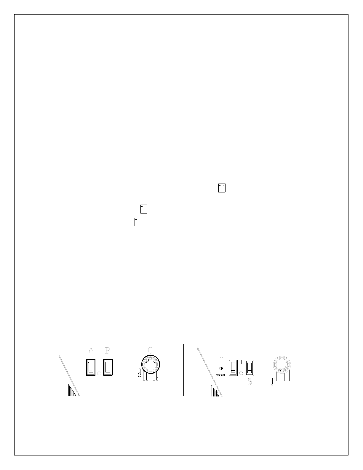
The controls are located on the lower right side of the wall mounted electric
fireplace. (FIGURE 1)
A. MAIN ON/OFF SWITCH
The switch has two ON positions marked with and “Manual”. The
“Manual“ position is for manual operation. In this position the built-in remote
control is by-passed. The position is for operating the unit with the provided
remote control. When in position the unit is operated with the ON and OFF
buttons of the remote control. When the switch is in the center position the unit is
off.
B. HEATER ON/OFF SWITCH
The HEATER ON/OFF SWITCH supplies power to the heater fan and the heater
element.
C. HEATER THERMOSTAT CONTROL
To adjust the temperature to your individual requirements, turn the thermostat
control clockwise all the way to turn on the heater. When the room reached the
desired temperature, turn the thermostat knob counter clockwise until you hear a
click. Leave in this position to maintain the room temperature at this setting. For
additional heat, turn clockwise until you hear the click again and the heater will turn
on. To turn the heater off, switch the HEATER ON/OFF SWITCH to the OFF
position.
MOD 0 MOD A
FIGURE 1 (LOWER RIGHT SIDE)
3
RESETTING THE TEMPERATURE CUTOFF SWITCH
This unit is equipped with a thermostat that controls the temperature of the room.
It does this by turning the heater on and off. The heater is protected with a safety
device to prevent overheating. Should the heater overheat, an automatic cut out
will turn the heater off and it will not come back on without being reset. To reset
the temperature cut-off switch turn the main power switch to the OFF position
and wait five minutes before switching the unit back on.
CAUTION
If you need to continuously reset the heater, unplug the unit and call Dimplex
North America Limited at 1-800-668-6663.
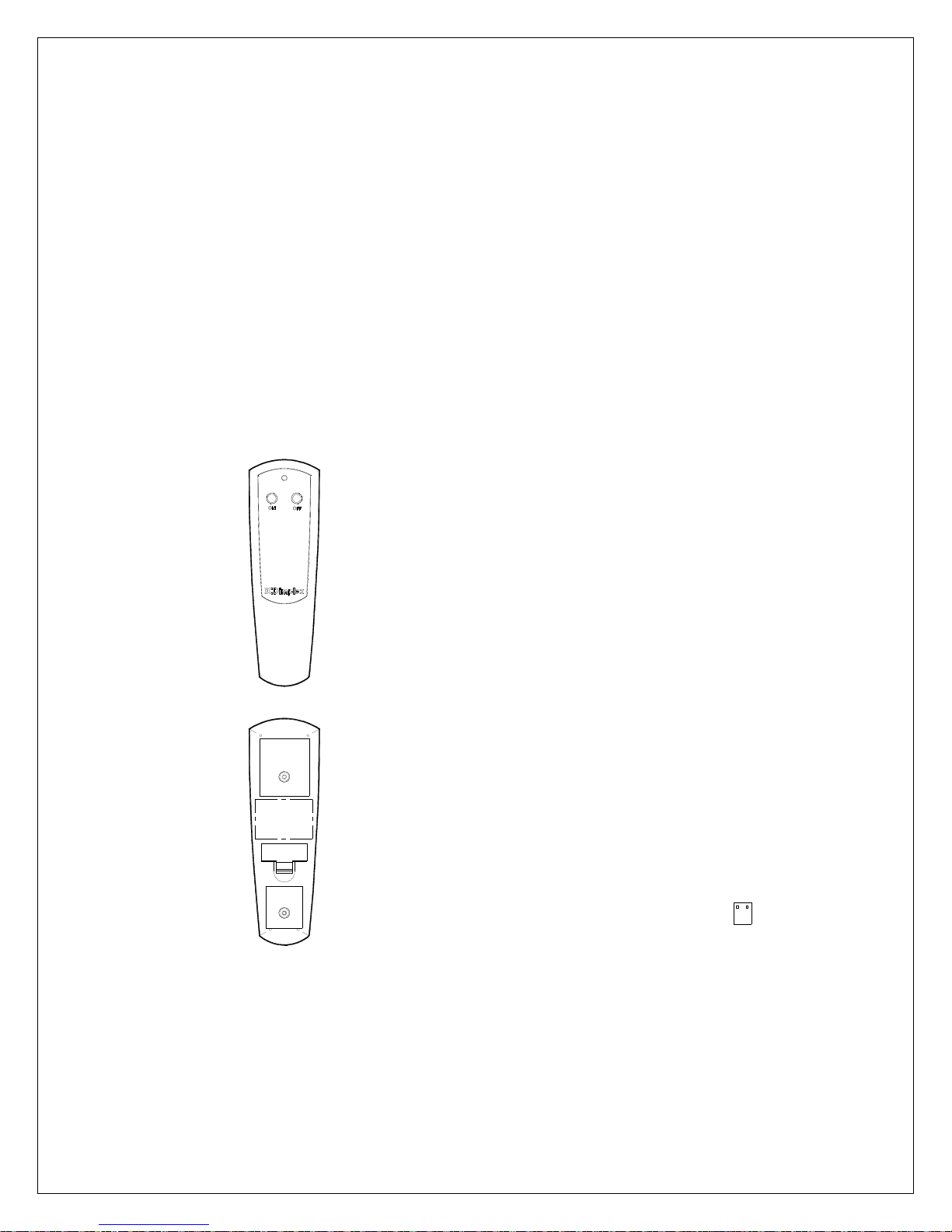
REMOTE CONTROL USAGE
This fireplace is supplied with a radio frequency remote control. This remote
control has a range of approximately 50 feet (15.25m); it does not have to be
pointed at the fireplace and can pass through most obstacles (including walls). It is
supplied with one of 243 independent frequencies to prevent interference with
other units. The frequency code is indicated on the back of the transmitter.
Note: Ensure that the fireplace 3 position
switch is set to the remote control setting.
To operate, push the ON button to turn fireplace
on, push the OFF button to turn the fireplace off.
BATTERY REPLACEMENT
To replace the battery, slide battery cover open
on the hand held transmitter. Correctly install
one 12 volt (A23) battery in the battery holder.
Close the batter cover.
Remote Control Initialization
This procedure is required every time there is a
loss of power to the remote control in the
fireplace. (I.e. power failure, breaker tripped,
main power switch is turned off)
1. Ensure that power is supplied through main
service panel.
2. Locate manual controls.
3. Toggle the main power switch, to the“
”
position.
4. Press ON button located on the remote control
transmitter. This will synchronize the remote
control transmitter and receiver.
4
MAINTENANCE
WARNING: Disconnect power before attempting any maintenance or cleaning to
reduce the risk of fire, electric shock or damage to persons.
LIGHT BULB REPLACEMENT
Allow at least 5 minutes for light bulbs to cool before touching bulbs to avoid
accidental burning of skin.
Light bulbs need to be replaced when you notice a dark section of the flame or
when the clarity and detail of the log exterior disappears. There are two bulbs
under the log set which generate the flames and embers.
TOOL REQUIREMENTS: Slot screw driver
HELPFUL HINTS
It is a good idea to replace all light bulbs at one time if they are close to the end of
their rated life. Group replacement will reduce the number of times you need to
open the unit to replace light bulbs.
LOWER LIGHT BULB REQUIREMENTS: Quantity of 3 – 35 Watt Clear Halogen
Lamps, 120 Volt, G9 base. DO NOT EXCEED 35 WATTS PER BULB.
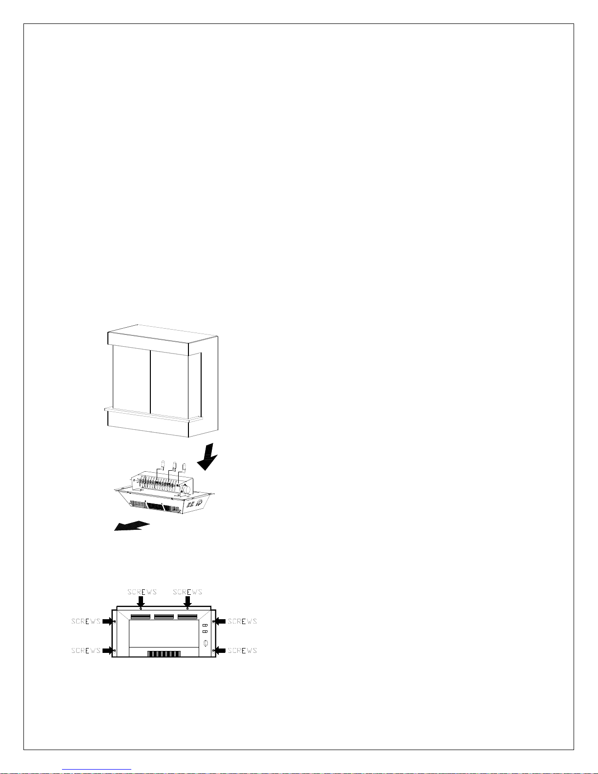
BULB REPLACEMENT
FIGURE 2
FIGURE 3
1. Unplug the unit from the outlet.
2. Remove the two mounting screws from the
bottom front of the heater assembly.
(FIGURE 3)
3. Loosen but do not remove the four heater
and light assembly mounting screws
located on the bottom sides of the wall
mounted electric fireplace. (FIGURE 3)
4. Slide the heater and light assembly forward
to release it from the bottom of the wall
mounted electric fireplace (FIGURE 2).
5. Place heater and light assembly on a flat
surface and examine the bulbs to determine
which bulb(s) required replacement
6. Remove the burnt out bulb(s) by gently
pulling straight out of socket. If bulbs are
difficult to remove from socket move the
bulb from side to side while pulling being
careful not to damage the light socket.
7. Insert new bulb(s).
8. Install the heater and light assembly onto
the four mounting screws.
9. Slide the assembly backwards to lock it into
position.
10. Tighten the four heater and light assembly
mounting screws.
11. Install the two front mounting screws.
12. Plug in the wall mounted electric fireplace.
5

GLASS CLEANING
The front glass is cleaned in the factory during the assembly operation. During
shipment, installation, handling, etc., the front glass may collect dust particles,
these can be removed by dusting lightly with a clean dry cloth.
To remove fingerprints or other marks, the glass can be cleaned with a damp cloth.
The glass should be completely dried with a lint free cloth to prevent water spots.
To prevent scratching, do not use abrasive cleaners or spray liquids on the glass
surface.
WALL MOUNTED ELECTRIC FIREPLACE SURFACE CLEANING
To remove fingerprints or other marks, the exterior finish can be cleaned with a
damp cloth with a mild detergent. The surface should be completely dried with a
lint free cloth to prevent water spots.
To prevent scratching, do not use abrasive cleaners or spray liquids on any
surface.
6
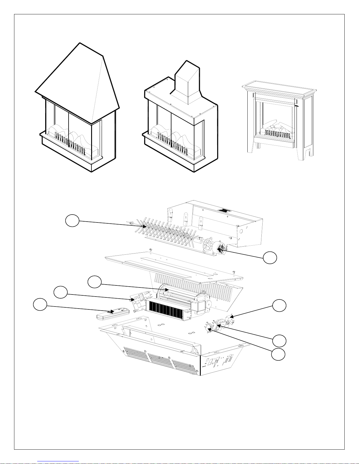
EXPLODED VIEW
EWM-COPPER EWM-SS DFP20-BW1009
12
08
07
05
11
04
02
01
7
 Loading...