

Dimplex DFI400LH, DFI600LH, DFI400RH Service Manual
Service Manual
Model Part Number
DFI400LH 6909050141
DFI400RH 6909050142
DFI600LH 6909050161
IMPORTANT SAFETY INFORMATION: Always read this manual rst before attempting to service this cassette. For your
safety, always comply with all warnings and safety instructions contained in this manual to prevent personal injury or property damage.
Dimplex North America Limited
1367 Industrial Road Cambridge ON Canada N1R 7G8
1-888-346-7539 www.dimplex.com
In keeping with our policy of continuous product development, we reserve the right to make changes without notice.
© 2013 Dimplex North America Limited
REV PCN DATE
00 - 11-OCT-13
7400750000R00

TABLE OF CONTENTS
Operation ...........................................................3
Maintenance .........................................................4
Exploded Parts Diagram ...............................................5
Replacement Parts List ................................................5
Wiring Diagram ......................................................6
Remote Control Receiver Replacement ..................................7
Power Board Replacement ............................................7
Switch Replacement . . . . . . . . . . . . . . . . . . . . . . . . . . . . . . . . . . . . . . . . . . . . . . . . . . 7
Thermostat Replacement . . . . . . . . . . . . . . . . . . . . . . . . . . . . . . . . . . . . . . . . . . . . . . 8
Potentiometer Replacement ...........................................8
Power Cord / Receptacle Replacement ...................................8
Fuse / Fuse Assembly Replacement .....................................8
Light Assembly Replacement ..........................................9
Fan Assembly Replacement ............................................9
Troubleshooting Guide ...............................................10
Always use a qualied technician or service agency to repair this cassette.
!
NOTE: Procedures and techniques that are considered important enough to emphasize.
CAUTION: Procedures and techniques which, if not carefully followed, will result in damage to the equipment.
WARNING: Procedures and techniques which, if not carefully followed, will expose the user to the risk of re, serious
injury, or death.
2 www.dimplex.com
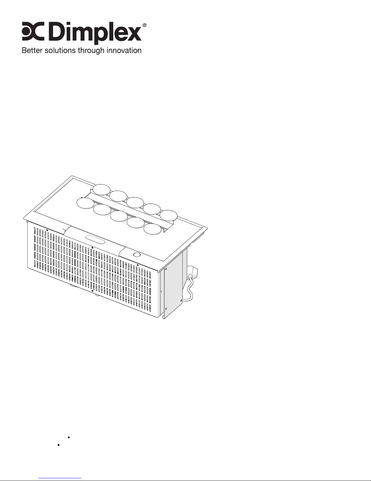
OPERATION
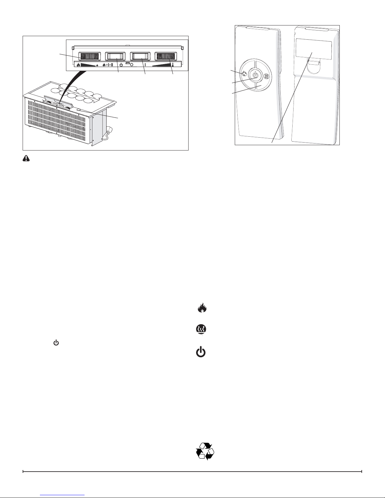
Figure 1
C
B
Remote Control
Sensor
CAUTION: During operation ensure that the receptacle
cord is positioned so that the face is perpendicular to the
oor.
!
NOTE: Always ensure that the appliance is in an upright
position before operating the unit.
!
NOTE: When the cassette is used in an environment
where background noise is very low, it may be possible to
hear a sound which is related to the operation of the ame
effect. This is normal and should not be a cause for concern.
The manual controls for the cassette are located on the top
of the unit, below the control cover. (Figure 1)
A. On/Off Switch
Supplies power to the cassette.
B. Mode Selector Switch
Press once to turn on the ame effect. This will be indicated
by an audible “beep”. Although the lights turn on immedi-
ately it will take 30 seconds before the ame effect starts.
• Press again to give ame effect and heat*. This will be
indicated by two “beeps”.
• Press again to return to ame effect only. This will be
indicated by one “beep”.
• Press to put re in to standby mode. This will be
indicated by one “beep”.
C. Flame Intensity Control
Adjusts the intensity of the ame effect when the heater
has been activated.
Turning the control knob clockwise to decrease the inten-
sity of the ame effect. Turning the control knob counterclockwise will increase the ame effect.
!
NOTE: Give the ame generator some time to react to
changes you may make on the ame control knob.
!
NOTE: When the water tank is empty the unit will turn
off after 30 seconds. See instructions under Maintenance
Section for relling tank. When this procedure is complete,
the main lamps will illuminate but it will take 30 seconds
before the ames return.
A
D
Figure 2
Flame
Button
Standby
Button
Heat
Button
Battery Cover
D. Thermostat Control*
To adjust the temperature to your individual requirements,
turn the thermostat control clockwise all the way to turn on
the heater. When the room reaches the desired temperature, turn the thermostat knob counter-clockwise until you
hear a click. Leave thermostat in this position to maintain
the room temperature at this setting. For additional heat,
turn clockwise until you hear the click again and the heater
will turn on.
* Only applicable when the Dimplex heater has been
plugged into the receptacle.
Remote Control
The On/Off Switch must be in the ‘ON’ ( I ) position in order
for the remote control to operate. There are 3 buttons on
the remote control. (Figure 2)
!
NOTE: To operate correctly, the remote control must be
pointed towards the remote control sensor.
The remote control functions are as follows:
Press once to turn on Flame effect only. This will be
indicated by one beep.
Press once to turn on heat and Flame effect. This will
be indicated by two beeps.
Standby - This will be indicated by one beep.
!
NOTE: Once the mist has been activated, the unit will
have to be turned Off, using either the switches on the unit,
or the standby button on the remote control, then back on
to return to ame effect operation only.
Battery Replacement
To replace the battery:
1. Slide battery cover open on the remote control (Figure
2).
2. Install two 1.5 Volt (AAA) batteries in the battery holder.
3. Close the battery cover.
Battery must be recycled or disposed of properly.
Check with your Local Authority or Retailer for recycling advice in your area.
3
 Loading...